Allen-Bradley 1747-ASB Installation Instructions Manual
- Taper
- Installation Instructions Manual

Publication 1747-IN014C-EN-P - January 2003
Installation Instructions
Remote I/O Adapter Module
(Catalog Number 1747-ASB)
Inside ................................................................................................page
Hazardous Location Considerations .........................................................2
Environnements dangereux ......................................................................2
1747-ASB Module Overview ....................................................................3
Required Tools and Equipment .................................................................4
Determining System Power Requirements...............................................4
Slot Addressing.........................................................................................5
Configuring the Module ............................................................................6
Installing the Module..............................................................................10
Connecting RIO Link Devices ..................................................................11
Wiring a Processor Restart Lockout Switch ...........................................14
Installing I/O Module Addressing Labels ...............................................15
Performing System Start-up ...................................................................17
Checking Operation.................................................................................17
Specifications .........................................................................................18
For More Information ..............................................................................19

2 Remote I/O Adapter Module
Publication 1747-IN014C-EN-P - January 2003
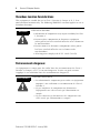
Hazardous Location Considerations
This equipment is suitable for use in Class I, Division 2, Groups A, B, C, D or
non-hazardous locations only. The following WARNING statement applies to use in
hazardous locations.
Environnements dangereux
Cet équipement est conçu pour être utilisé dans des environnements de Classe I,
Division 2, Groupes A, B, C, D ou non dangereux. La mise en garde suivante
s’applique à une utilisation dans des environnements dangereux.
WARNING
!
EXPLOSION HAZARD
• Substitution of components may impair suitability for Class
I, Division 2.
• Do not replace components or disconnect equipment
unless power has been switched off or the area is known to
be non-hazardous.
• Do not connect or disconnect components unless power
has been switched off or the area is known to be
non-hazardous.
• All wiring must comply with N.E.C. article 501-4(b).
AVERTISSEMENT
!
DANGER D’EXPLOSION
• La substitution de composants peut rendre cet équipement
impropre à une utilisation en environnement de Classe I,
Division 2.
• Ne pas remplacer de composants ou déconnecter
l'équipement sans s'être assuré que l'alimentation est
coupée.
• Ne pas connecter ou déconnecter des composants sans
s'être assuré que l'alimentation est coupée.

Remote I/O Adapter Module 3
Publication 1747-IN014C-EN-P - January 2003
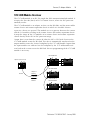
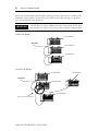
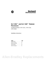
1747-ASB Module Overview
The 1747-ASB module is an SLC 500 single-slot, RIO communication link module. It
occupies the first slot (slot 0) of a 1746 remote chassis, where the SLC processor
normally resides.
The 1747-ASB module is an adapter, or slave, on the RIO link, and the master of the
remote chassis and remote expansion chassis in which it is installed. Remote
expansion chassis are optional. The module acts as a gateway between the scanner
and the I/O modules residing in the remote chassis and remote expansion chassis.
It maps the image of the I/O modules in its remote chassis and remote expansion
chassis directly to the SLC or PLC processor image.
Output data is sent from the scanner of either the SLC or PLC local chassis to the
1747-ASB module across the RIO link. This data is automatically transferred to the
output modules across the chassis backplane by the 1747-ASB module. Inputs from
the input modules are collected via the backplane by the 1747-ASB module and
sent back to the scanner across the RIO link. No user programming of the 1747-ASB
module is necessary.
Supervisory SLC (or PLC)
RIO Link
Outputs to
Modules
Inputs from
Modules
1747-ASB Module
Remote Chassis
Remote Expansion Chassis
1747-ASB Module
Remote Chassis
1747-ASB Module
Remote Chassis
Remote Expansion Chassis

4 Remote I/O Adapter Module
Publication 1747-IN014C-EN-P - January 2003
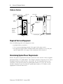
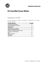
Hardware Features
Required Tools and Equipment
Have the following tools and equipment ready:
• medium blade screwdriver
• (2) 1/2 watt terminating resistors (See page 18 for correct size.)
• an adequate length of RIO communication cable (Belden™ 9463) for your
specific application. (See page 18 for maximum cable distances.)
Determining System Power Requirements
Review the power requirements of your system to ensure that the chassis supports
placement of the 1747-ASB module. The adapter consumes 600 mA at 5V dc. For a
detailed list of device load currents, refer to the SLC 500 Fixed Hardware Style
Installation and Operation Manual, publication number 1747-6.21; the SLC 500
Modular Hardware Style User Manual, publication number 1747-UM011, or the
appropriate Technical Data sheet.
U
FOR HAZ. LOC. A196
L
SLC 500
CAT SER
SERIAL NO. FRN
SA
ADAPTER
1 2 3 7 8
SW1
O
N
1 2 3 7 8
SW2
O
N
1 2 3 546
546
546
78
SW3
O
N
IMPORTANT :
INST ALL IN SLOT ZERO OF MODULAR CHASSIS ONL Y
REMOTE I/O ADAPTER MODULE
F AC 1M MADE IN USA
CURRENT REQUIREMENT : 375mA
LISTED IND. CONT . EQ.
CLASS 1, GROUPS A, B, C AND D, DIV . 2
OPERATING
TEMPERATURE
CODE T3C
1 23 45 6 7 8
SW1
1 2 3 4 5 6 7 8
SW2
1 2 3 456 7 8
SW3
O
N
O
N
LINE 1
SHLD
LINE 2
NC
IN
RET
(MSB)
LOGICAL
RACK
(LSB)
LOGICAL
GROUP
BAUD
RA TE
PRI/COMP
RSV
(MSB)
(LSB)
IMAGE
SIZE
HLS
PRL
RESP
LAST CHA
ADDR
MODE
SP MODE
KEY
1747-ASB
ST A TUS
COMM F AUL T
FAULT LED
(Red)
COMM LED
(Green)
Status
Display
Door
Label
Cable Tie Slots
Self-Locking Tab
DIP Switches
Manufacturing
Test Plug
RIO Link and
Processor
Restart
Lockout
Connector

Remote I/O Adapter Module 5
Publication 1747-IN014C-EN-P - January 2003
Slot Addressing
Slot Numbering
The 1747-ASB module is capable of controlling 30 slots. When expansion chassis
are used, the 1747-ASB module treats all of the I/O modules as if they are installed
in a single chassis.
The remote chassis and remote expansion chassis slots are numbered from 0 to 30.
The 1747-ASB module must reside in slot 0. Slots numbered 31 and above cannot
be used.
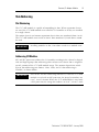
Addressing I/O Modules
SLC and PLC processors address the I/O modules residing in the chassis by logical
rack and logical group. Slot addressing refers to how each chassis slot is assigned a
specific amount of the 1747-ASB module image. The amount depends on which
type of slot addressing you choose; 2-slot, 1-slot, and 1/2-slot addressing is
available, as shown below.
IMPORTANT
Installing modules in slot 31 or above results in a module error.
IMPORTANT
Due to SLC and PLC addressing differences, when the 1747-ASB
module is used with an SLC processor, the image bit numbers are
0 to 7, 8 to 15 decimal. When the 1747-ASB module is used with
a PLC processor, the image bit numbers are 0 to 7, 10 to 17 octal.

6 Remote I/O Adapter Module
Publication 1747-IN014C-EN-P - January 2003
For more information on addressing, refer to the Remote I/O Adapter Module User
Manual, publication number 1747-6.13.
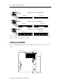
Configuring the Module
The 1747-ASB module parameters are configured by three DIP switches, shown
below.
2-Slot
Addressing
Input Image Output Image
Two slots are addressed as one logical group.
1-Slot
Addressing
Input Image Output Image
One slot is addressed as one logical group.
1/2-Slot
Addressing
Input Image
Output Image
One slot is addressed as two logical groups.
Slot Slot
Slot Slot
Slot
Slot
Slot Slot
SLC 500
CAT SER
SERIAL NO. FRN
U
L
SA
1 2 3 45678
SW1
O
N
1 2 3 45678
SW2
O
N
1 2 3 45678
SW3
O
N
IMPORTANT :
INST ALL IN SLOT ZERO OF MODULAR CHASSIS ONLY
REMOTE I/O ADAPTER MODULE
F AC 1M MADE IN USA
CURRENT REQUIREMENT : 375mA
LISTED IND. CONT . EQ.
FOR HAZ. LOC. A196
CLASS 1, GROUPS A, B, C AND D, DIV . 2
OPERATING
TEMPERATURE
CODE T3C
DIP Switches

Remote I/O Adapter Module 7
Publication 1747-IN014C-EN-P - January 2003
Configuration Parameters
The DIP switches allow you to configure the following items:
• Starting Logical Rack Number (Logical Rack) - is the 1747-ASB module’s
starting logical rack number in the scanner’s image.
• Starting Logical Group Number (Logical Group) - is the 1747-ASB
module’s starting logical group number within the scanner’s image.
• Baud Rate (Baud Rate) - is the 1747-ASB module’s RIO link communication
rate. The baud rate must be the same for all adapters on the RIO link.
• Primary/Complementary SLC Chassis (PRI/COMP) - determines
whether the 1747-ASB module appears to the scanner as a primary or
complementary chassis.
• Adapter Image Size (IMAGE SIZE) - indicates the I/O image size to be
reserved for the adapter. It can be any size between 2 and 32 groups in
2 logical group increments.
• Hold Last State (HLS) - determines whether the discrete output modules
are held in their last state when:
– RIO link communication with the 1747-ASB module is lost.
– The scanner inhibits the 1747-ASB module.
– The scanner sends Reset, Adapter Decide commands to the 1747-ASB
module.
• Processor Restart Lockout (PRL) - determines whether the 1747-ASB
module automatically resumes RIO link communications if communication is
lost and then restored.
• Link Response Time (RESP) - selects restricted or unrestricted RIO link
response time.
• Last Chassis/PLC-3 Backup (LAST CHA) - When the 1747-ASB module is
used with a PLC-2 or PLC-5, this switch indicates to the scanner that the
1747-ASB module is the last adapter mapped into the 1747-ASB module’s
highest logical rack. When using a PLC-3 processor, the switch determines
whether the 1747-ASB module supports the PLC-3 backup function.
• Addressing Mode (ADDR MODE) - determines the 1747-ASB module’s
remote chassis and remote expansion chassis addressing mode. 2-slot,
1-slot, and 1/2-slot are available.
• Specialty I/O Mode (SP MODE) - determines whether the 1747-ASB
module discretely maps or block transfer maps specialty I/O modules in its
remote chassis and remote expansion chassis.
• I/O Module Keying (KEY) - determines if the 1747-ASB module saves its
current I/O module and DIP switch configuration to its non-volatile memory,
or if the 1747-ASB module compares the current I/O module and DIP switch
configuration to the one saved in its non-volatile memory.

8 Remote I/O Adapter Module
Publication 1747-IN014C-EN-P - January 2003
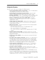
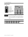
Dip Switch Settings
IMPORTANT
The ASB module can be configured as any logical rack number
from 0 to 77 octal. Rack numbers are determined by setting
switches SW1-1 through SW1-6, with ON equivalent to logical 0
and OFF equivalent to logical 1. Then, interpret this 6-bit binary
value as octal with SW1-6 as the least significant bit (LSB). For
example:
SW1-1 SW1-2 SW1-3 SW1-4 SW1-5 SW1-6 Rack
ON OFF ON ON ON OFF 21 (octal)
17 (decimal)
(0) (1) (0) (0) (0) (1)
1
O
N
2456783
SW1
Logical Rack Number Bit 5
(Most Significant Bit)
Logical Rack Number Bit 4
Logical Rack Number Bit 3
Logical Rack Number Bit 2
Logical Rack Number Bit 1
Logical Rack Number Bit 0 (LSB)
Logical Group Number Bit 1 (MSB)
Logical Group Number Bit 0
(Least Significant Bit)
Local Rack Number
ON = 0 OFF = 1
Local Group Number
78Group
ON ON 0 (default)
ON OFF 2
OFF ON 4
OFF OFF 6

Remote I/O Adapter Module 9
Publication 1747-IN014C-EN-P - January 2003
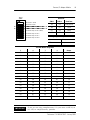
IMPORTANT
If you are not using complementary I/O, you must set SW2-3 to
the OFF, or complementary, position.
1
O
N
2456783
SW2
Baud Rate Bit 1 (MSB)
Baud Rate Bit 0 (LSB)
Primary/Complementary Chassis
Reserved
ASB Module Image Size Bit 3 (MSB)
ASB Module Image Size Bit 2
ASB Module Image Size Bit 1
ASB Module Image Size Bit 0
Baud Rate
SW2-1 SW2-2 Baud Rate
ON ON 57.6K (default)
ON OFF 115.2K
OFF ON 230.4K
OFF OFF INVALID
Primary/Complementary Chassis
ON Primary
OFF Complementary
1747-ASB Module Image Size
5 6 7 8 Groups
ON ON ON ON 2
ON ON ON OFF 4
ON ON OFF ON 6
ON ON OFF OFF 8
ON OFF ON ON 10
ON OFF ON OFF 12
ON OFF OFF ON 14
ON OFF OFF OFF 16
OFF ON ON ON 18
OFF ON ON OFF 20
OFF ON OFF ON 22
OFF ON OFF OFF 24
OFF OFF ON ON 26
OFF OFF ON OFF 28
OFF OFF OFF ON 30
OFF OFF OFF OFF 32

10 Remote I/O Adapter Module
Publication 1747-IN014C-EN-P - January 2003
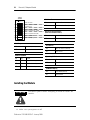
Installing the Module
1. Make sure system power is off.
ATTENTION
!
Disconnect power before attempting to install or remove the
module.
1
O
N
2456783
SW3
Hold Last State
Processor Restart Lockout
Link Response
Last Chassis/PLC-3 Backup
Addressing Mode Bit 1 (MSB)
Addressing Mode Bit 0 (LSB)
Specialty I/O Mode
I/O Module Keying
Hold Last State
ON Hold Last State
OFF Do not Hold Last State (default)
Processor Restart Lockout
(after lost communications)
ON Automatic Restart (default)
OFF Processor Lockout
Last Chassis
ON Not Last Chassis (default)
OFF Last Chassis
Specialty I/O Mode
ON Discrete (default)
OFF Block Transfer
I/O Module Keying
ON Save Mode (default)
OFF Check Mode
Link Response
ON Restricted (default)
OFF Unrestricted
Addressing Mode
ON ON Invalid
ON OFF 1-slot Addressing (default)
OFF ON 1/2-slot Addressing
OFF OFF 2-slot Addressing

Remote I/O Adapter Module 11
Publication 1747-IN014C-EN-P - January 2003
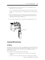
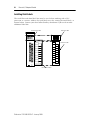
2. Install the module in slot 0 of the remote chassis by aligning the circuit
board with the chassis card guide.
The 1747-ASB module must be installed only in slot 0 (the left slot) of the
remote chassis. Do not install the 1747-ASB module in the remote expansion
chassis.
3. Slide the module into the chassis until the top and bottom tabs lock into
place. To remove the module, press and hold the release located on each
self-locking tab and slide the module out.
4. Cover all unused slots with the Card Slot Filler, Catalog Number 1746-N2.
Connecting RIO Link Devices
Link Wiring
The modules are connected in a daisy chain configuration on any RIO link. A daisy
chain network is formed by connecting network devices together in a serial manner
using Belden 9463 cable. Belden 9463 cable is the only approved cable for
Allen-Bradley RIO links.
The total number of adapters allowed on the RIO link is:
• 32 if the scanner and all adapters on the RIO link have extended node
capability
• 16 if the scanner or any adapter does not have extended node capability
Module Release
Card Guide

12 Remote I/O Adapter Module
Publication 1747-IN014C-EN-P - January 2003
There are no restrictions governing the spacing between the devices, as long as the
maximum cable distance is not exceeded. Refer to the table on page 18 for baud
rate and maximum cable distances.
Correct Link Wiring
Incorrect Link Wiring
IMPORTANT
No two devices can be connected to the same point on the link.
An example of correct and incorrect link wiring is shown below.
To Scanner
1747-ASB Module
1747-ASB Module
1747-ASB Module
To Scanner
1747-ASB Module
1747-ASB Module
1747-ASB Module
1747-ASB Module
This is an incorrect connection!

Remote I/O Adapter Module 13
Publication 1747-IN014C-EN-P - January 2003
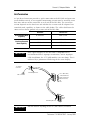
Link Termination
A 6-pin keyed connector provides a quick connection to the RIO link and processor
restart lockout switch. A user-supplied terminating resistor must be attached across
lines one and two of the connector at each end of the RIO link. The size of the
resistor depends on the baud rate and whether the scanner and all adapters have
extended node capability, as shown in the table below. The cable shield must be
connected to chassis ground only at one end of the RIO link.
Baud Rate Resistor size
Using Extended Node
Capability
All Baud Rates 82Ω 1/2 Watt
Not Using Extended
Node Capability
57.6K baud 150Ω 1/2 Watt
115.2K baud 150Ω 1/2 Watt
230.4K baud 82Ω 1/2 Watt
IMPORTANT
If the signal integrity on the RIO link is compromised by
environmental noise, improper termination, and/or improper
cable installation, the 1747-ASB module scan rate drops. This is
indicated by a pronounced flickering of the status display.
IMPORTANT
Do not connect anything to the NC (No Connect) terminal.
To Scanner’s
Connector
Chassis Ground
Terminating Resistor
Terminating Resistor
Blue
Shield
Clear
Line 1 (Blue Wire)
SHLD (Shield wire)
LINE 2 (Clear wire)
NC (No Connect)
IN
RET

14 Remote I/O Adapter Module
Publication 1747-IN014C-EN-P - January 2003
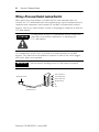
Wiring a Processor Restart Lockout Switch
When processor restart lockout is enabled (SW3-2) and communications are
restored, the 1747-ASB module does not respond to any type of communication, or
communication commands until terminals IN and RET are momentarily shorted
together. This occurs while the RIO scanner is attempting to communicate with the
1747-ASB module.
Use a momentary switch (Class 1, Division 2) to short terminals IN and RET
together. The processor restart lockout is removed as soon as the switch toggles
back to the open circuit position.
ATTENTION
!
Cycling power on any 1747-ASB module chassis removes the
processor restart lockout condition by re-initializing the
1747-ASB module.
IMPORTANT
Do not connect anything to the NC (No Connect) terminal.
Momentary Switch
14 - 24 gauge wire
(maximum 5 feet)
LINE 1 (Blue wire)
SHLD (Shield wire)
LINE 2 (Clear wire)
NC (No Connect)
IN
RET

Remote I/O Adapter Module 15
Publication 1747-IN014C-EN-P - January 2003
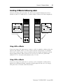
Installing I/O Module Addressing Labels
Attach the Remote PLC or Remote SLC label to the outside bottom of each I/O
module in your 1747-ASB chassis, as shown below. Fill out each label completely.
Using a SLC as a Master
If you are using a SLC processor as a master, each I/O module is addressed by the
physical slot number of the 1747-SN scanner and the word that the I/O module
uses in the scanner image. Data is transferred on the network by logical rack and
logical group number. Refer to Remote I/O Scanner User Manual, publication
number 1747-6.6, for more information on the 1747-SN.
Using a PLC as a Master
If you are using a PLC processor as a master, each I/O module is addressed by
logical rack and logical group, regardless of what physical slot it is in. If using a
PLC processor as a master, attach octal labels.
BT Discrete
0 - 7 8 - 15
SN Slot
SN Word(s)
Remote SLC System
Rack Group(s)
BT
Discrete
0 - 7 10 - 17 0 - 7 8 - 15
SN Slot
SN Word(s)
INPUT INPUT
Remote PLC System
BT
Discrete
Remote SLC System
I:
O:
Rack Group(s)
Discrete
0 - 7 10 - 17
I:
O:
Remote PLC
System
BT
Remote SLC Label
Remote PLC® Label

16 Remote I/O Adapter Module
Publication 1747-IN014C-EN-P - January 2003
Installing Octal Labels
The octal filter and door label kits must be used when working with a PLC
processor as a master. Adhere the octal labels over the existing decimal labels, as
shown below. Contact your local Allen-Bradley distributor if you need to order
additional label kits.
INPUT
1746-XXXX 1746-XXXX (OCTAL)
OCTAL
Decimal Filter Label
Octal Filter Label
Octal Door Label
Decimal Door Label

Remote I/O Adapter Module 17
Publication 1747-IN014C-EN-P - January 2003
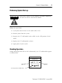
Performing System Start-up
Follow the steps below:
1. Cycle power one last time in save mode (SW3-8 ON).
2. Remove power from the system.
3. Remove the 1747-ASB module and set SW3-8 to the OFF position (check
mode).
4. Replace the 1747-ASB module in slot 0.
5. Apply power to your system.
Checking Operation
During normal operation (PLC or SLC in Run mode), the 1747-ASB module appears
as shown below.
ATTENTION
!
Never insert, remove, or wire modules with power applied to
the chassis or devices wired to the module.
ADAPTER
Red FAULT
LED is off.
Green COMM
LED is on.
Status display indicates a run condition.

18 Remote I/O Adapter Module
Publication 1747-IN014C-EN-P - January 2003
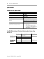
Specifications
Adapter Operating Specifications
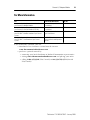
Baud Rate Determination of Maximum Cable Length and Terminating
Resistor Size
Backplane Current Consumption 375 mA at 5V dc
Operating Temperature 32°F to 140°F
(0°C to 60°C)
Storage Temperature -40°F to +185°F
(-40°C to +85°C)
Humidity 5% to 95% non-condensing
Noise Immunity NEMA standard ICS 2-230
Vibration Displacement: 0.015 inch, peak-to-peak at 5-57 Hz
Acceleration: 2.5Gs at 57-2000 Hz
Shock (operating) 30Gs
Agency Certification
(when product or packaging is marked)
• UL Listed
• CSA certified
• Class I, Division 2 Groups A, B, C, D
• CE compliant for all applicable directives
• Marine Certified
• C-tick marked for all applicable acts
Baud Rate Maximum Cable Distance
(Belden 9463)
Resistor Size
Using Extended
Node Capability
57.6K baud 3048 meters (10,000 feet) 82Ω 1/2 Watt
115.2K baud 1524 meters (5,000 feet)
230.4K baud 762 meters (2,500 feet)
Not Using
Extended Node
Capability
57.6K baud 3048 meters (10,000 feet) 150Ω 1/2 Watt
115.2K baud 1524 meters (5,000 feet)
230.4K baud 762 meters (2,500 feet) 82Ω 1/2 Watt

Remote I/O Adapter Module 19
Publication 1747-IN014C-EN-P - January 2003
For More Information
If you would like a manual, you can:
• download a free electronic version from the internet:
www.theautomationbookstore.com
• purchase a printed manual by:
– contacting your local distributor or Rockwell Automation representative
– visiting www.theautomationbookstore.com and placing your order
– calling 1.800.963.9548 (USA/Canada) or 001.330.725.1574 (Outside
USA/Canada)
For Refer to this Document Pub. No.
A more detailed description on how to install and use
your Remote I/O Adapter Module.
Remote I/O Adapter Module
User Manual
1747-6.13
A more detailed description on how to install and use
your Remote I/O Scanner Module (1747-SN).
Remote I/O Scanner Module
User Manual
1747-6.6
A more detailed description on how to install and use
your SLC 500™ Modular Hardware Style Control
System.
SLC 500™ Modular Hardware
Style User Manual
1747-UM011
A more detailed description on how to install and use
your SLC 500™ Fixed Hardware Style Control
System.
SLC 500™ Fixed Hardware
Style Installation and Operation
Manual
1747-6.21

Publication 1747-IN014C-EN-P - January 2003 PN 40071-134-01(3)
Supersedes Publication 1747-IN014B-EN-P - May 2001 Copyright © 2007 Rockwell Automation, Inc. All rights reserved. Printed in Singapore.
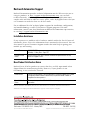
Rockwell Automation Support
Rockwell Automation provides technical information on the Web to assist you in
using its products. At http://support.rockwellautomation.com
, you can find
technical manuals, a knowledge base of FAQs, technical and application notes,
sample code and links to software service packs, and a MySupport feature that you
can customize to make the best use of these tools.
For an additional level of technical phone support for installation, configuration,
and troubleshooting, we offer TechConnect Support programs. For more
information, contact your local distributor or Rockwell Automation representative,
or visit http://support.rockwellautomation.com
.
Installation Assistance
If you experience a problem with a hardware module within the first 24 hours of
installation, please review the information that's contained in this manual. You can
also contact a special Customer Support number for initial help in getting your
module up and running.
New Product Satisfaction Return
Rockwell tests all of its products to ensure that they are fully operational when
shipped from the manufacturing facility. However, if your product is not
functioning, it may need to be returned.
Rockwell Automation, Allen-Bradley, SLC 500, PLC, and TechConnect are trademarks of Rockwell Automation, Inc.
Trademarks not belonging to Rockwell Automation are property of their respective companies.
United States 1.440.646.3223
Monday – Friday, 8am – 5pm EST
Outside United
States
Please contact your local Rockwell Automation representative for any
technical support issues.
United States Contact your distributor. You must provide a Customer Support case number
(see phone number above to obtain one) to your distributor in order to
complete the return process.
Outside United
States
Please contact your local Rockwell Automation representative for return
procedure.
-
 1
1
-
 2
2
-
 3
3
-
 4
4
-
 5
5
-
 6
6
-
 7
7
-
 8
8
-
 9
9
-
 10
10
-
 11
11
-
 12
12
-
 13
13
-
 14
14
-
 15
15
-
 16
16
-
 17
17
-
 18
18
-
 19
19
-
 20
20


Allen-Bradley 1747-ASB Installation Instructions Manual
- Taper
- Installation Instructions Manual
dans d''autres langues
- English: Allen-Bradley 1747-ASB
Documents connexes
-
 Allen-Bradley 1747-DCM Installation Instructions Manual
-
 Allen-Bradley 1747-SN Installation Instructions Manual
-
 Allen-Bradley SLC 5/05 Installation Instructions Manual
-
 Allen-Bradley SLC 5/05 Installation Instructions Manual
-
 AB Quality 1747-L514 Guide d'installation
-
 Allen-Bradley SLC 500 Series Installation Instructions Manual
-
 Allen-Bradley SLC 5/02 Installation Instructions Manual
-
 Allen-Bradley SLC 5/05 Installation Instructions Manual
-
 Allen-Bradley SLC 5/02 Installation Instructions Manual
-
 Allen-Bradley ControlNet 1747-SCNR Installation Instructions Manual