Rockford Fosgate FNP2414 Manuel utilisateur
- Catégorie
- Haut-parleurs de voiture
- Taper
- Manuel utilisateur

FNP2414
FNP2514
FNP2614U
FNP2614
Installation
& Operation
Páginas de Referencia para la Instalación
Schéma d’Installation
Installations Beiblatt
Istruzioni di Installation
COMPONENT SYSTEMS

– i –
Dear Customer,
Congratulations on your purchase of the world's finest brand of car audio speakers.
At Rockford Fosgate, we are fanatics about musical reproduction at its best, and we
are pleased you chose our product. Through years of engineering expertise, hand
craftsmanship, and critical testing procedures, we have created a wide range of
products that reproduce music with all the clarity and richness you deserve.
For maximum performance, we recommend you have your new Rockford Fosgate
product installed by an Authorized Rockford Fosgate Dealer, as we provide special-
ized training through Rockford Technical Training Institute (RTTI). Please read your
warranty and retain your receipt and original carton for possible future use.
Great product and competent installations are only a piece of the puzzle when it
comes to your system. Make sure that your installer is using 100% authentic instal-
lation accessories from Connecting Punch in your installation. Connecting Punch
has everything from RCA cables and speaker wire to Power line and battery con-
nectors. Insist on it! After all, your new system deserves nothing but the best.
To add the finishing touch to your new Rockford Fosgate image, order your Rockford
wearables, which include everything from T-shirts and jackets to hats and sunglasses.
To get a free brochure on Rockford Fosgate products and Rockford accessories, in
the U.S. call 480-967-3565 or FAX 480-967-8132. For all other countries, call
+001-480-967-3565 or FAX +001-480-967-8132.
PRACTICE SAFE SOUND™
CONTINUOUS EXPOSURE TO SOUND PRESSURE LEVELS OVER
100dB MAY CAUSE PERMANENT HEARING LOSS. HIGH POWERED
AUTOSOUND SYSTEMS MAY PRODUCE SOUND PRESSURE LEVELS
WELL OVER
130dB. USE COMMON SENSE AND PRACTICE SAFE
SOUND
.
If, after reading your manual, you still have questions regarding this product, we
recommend that you see your Rockford Fosgate dealer. If you need further assis-
tance, you can call us direct at 1-800-669-9899. Be sure to have your serial num-
ber, model number, and date of purchase available when you call.
The serial number can be found on the outside of the box. Please record it in the
space provided below as your permanent record. This will serve as verification of
your factory warranty and may become useful in recovering your product if it is ever
stolen.
Serial Number: __________________________________
Model Number:__________________________________

– ii –
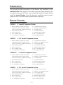
Introduction ..............................................................................................1
Package Contents......................................................................................1
Installation Considerations ........................................................................2
Mounting Location....................................................................................3
Installation ................................................................................................4
Troubleshooting ........................................................................................7
Specifications............................................................................................8
Warranty Information ................................................................................9
International Information ........................................................................10
Sections marked
TROUBLESHOOTING
include recommendations for
curing installation problems
Sections marked
INSTALLATION
include “slam dunk”
wiring connections
Welcome to Rockford Fosgate! This manual is designed to provide
information for the owner, salesperson and installer. For those of you
who want quick information on how to install this product, please turn
to the Installation Section of this manual or refer to the icons listed
below. Other information can be located by using the Table of
Contents. We, at Rockford Fosgate, have worked very hard to make
sure all the information in this manual is current. But, as we are con-
stantly finding new ways to improve our product, this information is
subject to change without notice.
GETTING STARTED
I
N
S
T
A
L
L
A
T
I
O
N
+ -
+ -
TROUBLE-
S
H
O
O
T
I
N
G
Visit our website for the latest information on all Rockford products.
TABLE OF CONTENTS

– 1 –
(2) FNP2401 Tweeters: includes 3/4" [20mm]
mylar dome tweeter, flush mount housing,
surface mount housing, wedge mount housing
(2) Tweeter Mounting Brackets
(4) #8-32 x .500 Screws
(8) #8 x .75 Phillips Screws
(2) .110 Female Fast-on Connectors
(2) .110 Male Fast-on Connectors
(2) FNP2404 4" Midrange Speakers
(2) 4" Speaker Grilles
(2) 4" Speaker Grille Rings
(2) FNP242x 2-Way Crossovers
(8) #8 x 1.25 Phillips Screws
(20') 18 Gauge Speaker Wire
(2) FNP2401 Tweeters: includes 3/4" [20mm]
mylar dome tweeter, flush mount housing,
surface mount housing, wedge mount housing
(2) Tweeter Mounting Brackets
(4) #8-32 x .500 Screws
(8) #8 x .75 Phillips Screws
(2) .110 Female Fast-on Connectors
(2) .110 Male Fast-on Connectors
(2) FNP2406U 6" Midrange Speakers
(2) 6" Speaker Grilles
(2) 6" Speaker Grille Rings
(2) FNP242x 2-Way Crossovers
(8) #8 x 1.25 Phillips Screws
(20') 18 Gauge Speaker Wire
(2) FNP2401 Tweeters: includes 3/4" [20mm]
mylar dome tweeter, flush mount housing,
surface mount housing, wedge mount housing
(2) Tweeter Mounting Brackets
(4) #8-32 x .500 Screws
(8) #8 x .75 Phillips Screws
(2) .110 Female Fast-on Connectors
(2) .110 Male Fast-on Connectors
(2) FNP2405 5-1⁄4" Midrange Speakers
(2) 5-1⁄4" Speaker Grilles
(2) 5-1⁄4" Speaker Grille Rings
(2) FNP242x 2-Way Crossovers
(8) #8 x 1.25 Phillips Screws
(20') 18 Gauge Speaker Wire
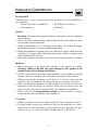
FNP2414 4" fanaticP Component System
FNP2614U 6" fanaticP Component System
FNP2514 5-1/4" fanaticP Component System
(2) FNP2401 Tweeters: includes 3/4" [20mm]
mylar dome tweeter, flush mount housing,
surface mount housing, wedge mount housing
(2) Tweeter Mounting Brackets
(4) #8-32 x .500 Screws
(8) #8 x .75 Phillips Screws
(2) .110 Female Fast-on Connectors
(2) .110 Male Fast-on Connectors
(2) FNP2406 6-1⁄2" Midrange Speakers
(2) 6-1⁄2" Speaker Grilles
(2) 6-1⁄2" Speaker Grille Rings
(2) FNP242x 2-Way Crossovers
(8) #8 x 1.25 Phillips Screws
(20') 18 Gauge Speaker Wire
FNP2614 6-1/2" fanaticP Component System
This manual provides information on the features and installation of the
fanaticP System. We suggest you save this manual for future reference. We
strongly recommend you have your Authorized Rockford Fosgate Dealer
install the fanaticP System. If you do choose to install the system yourself,
please be sure to read the entire manual before beginning.
INTRODUCTION
PACKAGE CONTENTS

– 2 –
Tools Needed
The following is a list of some of the tools necessary for the installation of
your speakers:
• Power Drill with assorted bits • #2 Phillips Screwdriver
• Tape Measure • Voltmeter
General
1. For safety, disconnect the negative lead from the battery prior to beginning
the installation.
2. Never run wires underneath the vehicle. Running the wires inside the vehi-
cle provides the best protection.
3. Avoid running wires over or through sharp edges. Use rubber or plastic
grommets to protect any wires routed through metal.
4. Mount the speakers/crossovers away from electrical sources (other than the
amplifier) i.e., power cables, electronic fuel pumps, vehicle computers, and
other potential noise sources.
5. Mount the speakers/crossovers away from areas of extreme heat or moisture.
Speakers
1. Make sure there is an area large enough of the speaker to mount.
Warning! Failure to do this can cause damage to the speaker if the
speaker frame is bent during installation.
2. Check to see that the location is deep enough for the speaker(s) and the
location does not interfere with the normal operation of the vehicle.
3. When mounting the speaker(s) in the door of a vehicle, make sure the
speaker(s) do not interfere with either the door or window operation.
4. When mounting the speaker(s) on the rear deck of the vehicle, check the
operation of the rear hatch or trunk lid. Make sure the torsion bars and
other moving parts are not obstructed by the speaker(s) installation.
• Please refer to the Specifications section of this manual for proper
mounting diameter and depth of the speaker(s).
Crossovers
1. Make sure there is a flat area large enough for the crossover to mount.
2. For best results, mount the crossover(s) next to the amplifier for a deco-
rative finish to the installation and provide an easy upgrade (no new
wires to run) for a bi-amp Rockford Fosgate system in the future.
I
N
S
T
A
L
L
A
T
I
O
N
+ -
+ -
INSTALLATION CONSIDERATIONS

– 3 –
A solid front stage with a good image is one of the most difficult tasks to
achieve in a vehicle. No car has the optimum listening environment. This
makes proper sound staging very difficult to accomplish. Most speakers
tend to be placed where they will fit easily, as opposed to where they can
perform the best. The mounting location of your speakers will have a great
effect on the sound quality of your stereo system. The special care taken to
place the speakers will yield many hours of listening enjoyment in return.
Several important recommendations should be followed.
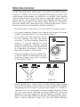
• Place the speakers where they have a direct path to the listening area.
• For the best integration between the midrange and tweeter, the tweeter
should be placed less than 2" from the midrange (Figure 1).
• If you cannot place the tweeter less than 2"
from the midrange, then place the tweeter
more than 7" from the midrange. Placing the
tweeter 2"-7" from the midrange can cause
destructive interference (frequency response
problems) which will affect the speaker's abil-
ity to reproduce the frequency range around
the crossover frequency of the system.
• Whenever possible, place the tweeter direct-
ly above or below the midrange as this max-
imizes the imaging (point source) capability
of the speakers (Figure 2).
Figure 1
2" or less
Figure 2-A
Figure 2-B
MOUNTING LOCATION
• Sound radiated from a “point source” provides the best stereo imaging
because the separation of the acoustical centers between the midrange
and tweeter for each channel is at the optimum distance. In a closed en-
vironment such as an automobile, horizontal speaker alignment (Figure
2-A) can cause severe amplitude and phase differences which will
degrade not only the imaging, but also the frequency response. This is
due to the path length differences between the midrange and tweeter.
With a vertical alignment (Figure 2-B), the path length difference

– 4 –
between the midrange and tweeter are reduced to a minimum. The result
is a negligible difference in path lengths between the midrange and
tweeter regardless of the proximity of the listener to the speakers.
Mounting the speaker with minimum path length difference will ensure
the best staging and imaging possible from your audio system.
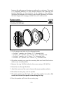
1. Cut the proper size hole for the midrange/woofer.
• For the 4” speaker, cut a 90mm (3
9
⁄
16
") diameter hole
• For the 5-1/4” speaker, cut a 114mm (4
15
⁄
32
") diameter hole
• For the 6” speaker, cut a 129mm (5
1
⁄
16
") diameter hole
• For the 6-1/2” speaker, cut a 139mm (5
1
⁄
2
") diameter hole
2. Place the mounting ring over the mounting hole and mark the location
of the screw mounting holes.
3. Remove the ring. Drill the holes for the screws using a 1/8" drill bit.
4. Route the wire through the hole.
5. Attach the wires and be sure to observe the proper speaker polarity.
6. Place the mounting ring over the speaker.
7. Place the speaker into the hole and screw the speaker into place. Be
careful not to bend the speaker frame during this step.
8. Press the speaker grille into the mounting ring.
INSTALLATION
I
N
S
T
A
L
L
A
T
I
O
N
+ -
+ -
Mounting the Midrange

– 5 –
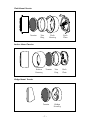
Flush Mount Tweeter
Tweeter
Surface Mount Tweeter
Trim
Ring
Back
Plate
Flush
Housing
Tweeter Trim
Ring
Back
Plate
Surface
Housing
Wedge Mount Tweeter
Tweeter Wedge
Housing

– 6 –
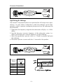
80Hz 500µF
100Hz 400µF
130Hz 300µF
200Hz 200µF
260Hz 150µF
400Hz 100µF
Crossover Connections
High-Passing the Midrange
The fanaticP Component Systems are optimized for full range music repro-
duction. In cases where a subwoofer is used, the midrange can be high-
passed in order to prevent overlapping frequncies from the midrange into
the subwoofer.
1. Determine the frequency range that the subwoofer will play (i.e.: 20Hz-
80Hz).
2. Use the low-pass crossover frequency of the subwoofer system (i.e.:
80Hz) as the high-pass crossover frequency for the midrange.
3. Select the appropriate capacitor value (i.e.: 500µF) to properly high-pass
the midrange.
4. Place the capacitor in series with the "+" terminal of the speaker.
Frequency
(Hertz)
Speaker
(4 ohms)
C1

– 7 –
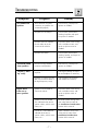
TROUBLESHOOTING
No sound from
speakers
Symptom Diagnosis Remedy
Check wiring, and repair or
replace as needed
Check system with known
working amplifier and repair
or replace as needed
Check for shorts in the wiring
with a volt/ohm meter, and
repair or replace wires as
needed
Check system with known
working speaker, and repair or
replace as needed
Wires between amplifier,
crossover, or speakers not
connected properly
Amplifier has no output
Speaker wires are shorted
to each other or to the
chassis of the vehicle
Speakers are blown
Incorrect wiring between
crossover and speakers
Excessive power from
amplifier
Equalizer in system (if avail-
able) has excessive boost in
the high frequency range
Check wiring, and repair or
replace as needed
Check gain settings on ampli-
fier and readjust as necessary
Check settings on equalizer
and readjust as necessary
Distorted sound
from speakers
Tweeters “burn
up” easily
Engine noise
from one or
more speakers
Check for shorts in the wiring
with a volt/ohm meter, and
repair or replace wires as
needed
Re-route speaker wiring away
from noise sources (refer to
the Installation Considerations
section of this manual)
Move crossovers away from
noise sources (refer to the
Installation Considerations
section of this manual)
Speaker wires shorted to
chassis of vehicle
Speaker wires are routed
near radiated noise source
(power cables, vehicle com-
puters, etc.)
Crossover is mounted near
radiated noise source
(power cables, vehicle com-
puters, etc.)
TROUBLE-
S
H
O
O
T
I
N
G

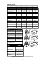
– 8 –
Model FNP2401
Nominal Diameter 3/4" (20mm)
Nominal Impedance 4Ω
Frequency Response 2.8kHz-20kHz
Fs 2.8kHz
Sensitivity 91dB
RMS Power Handling 50 Watts*
Mounting Diameter See drawings
Mounting Depth See drawings
* Power Ratings (PE) is established with recom-
mended filter network
Model FNP242x
Crossover Type 2-Way
Crossover Frequency 6.3kHz @ 4Ω
Crossover Slope 18dB/octave High-Pass
Full-Range Low-Pass
Filter Q 0.707 (Butterworth)
Tweeter Protection Optical Compression
Dimensions See drawings
System Model Number FNP2414 FNP2514 FNP2614U FNP2614
Midrange Model Number FNP2404 FNP2405 FNP2406U FNP2406
Nominal Diameter 4" 5
1
⁄
4
"
6" 6
1
⁄
2
"
Nominal Impedance 4Ω 4Ω 4Ω 4Ω
Frequency Response 100Hz-8kHz 60Hz-6kHz 61Hz-6kHz 55Hz-5kHz
Fs (Hz) 100Hz 60Hz 61Hz 55Hz
Qes .907 .705 .701 .926
Qms 3.372 2.896 2.58 3.558
Qts .715 .567 .551 .733
Vas (ft
3
/liter) .078/2.2 .29/8.1 .335/9.5 .59/16.7
Xmax (in/mm) .09/2.4 .11/2.9 .11/2.9 .11/2.9
Sensitivity 84.9dB 86.4dB 86.8dB 87.1dB
RMS Power Handling 50 Watts 50 Watts 50 Watts 50 Watts
Mounting Diameter 90.48mm 113.50mm 129mm 139.06mm
(3
9
⁄
16
") (4
15
⁄
32
") (5
1
⁄
16
") (5
1
⁄
2
")
M
ounting Depth 45mm (1
3
⁄4") 60mm (2
3
⁄
8
") 45mm (1
3
⁄
4
") 63mm (2
1
⁄
2
")
(Specifications are subject to change without notice)
SPECIFICATIONS

– 9 –
Rockford Corporation offers a limited warranty on Rockford Fosgate products on the following terms:
• Length of Warranty
1 year on speakers 30 days on speaker B-stock (receipt required)
3 years on electronics 90 days on electronic B-stock (receipt required)
1 year on source units
• What is Covered
This warranty applies only to Rockford Fosgate products sold to consumers by Authorized Rockford
Fosgate Dealers in the United States of America or its possessions. Product purchased by consumers
from an Authorized Rockford Fosgate Dealer in another country are covered only by that country’s
Distributor and not by Rockford Corporation.
• Who is Covered
This warranty covers only the original purchaser of Rockford product purchased from an Authorized
Rockford Fosgate Dealer in the United States. In order to receive service, the purchaser must provide
Rockford with a copy of the receipt stating the customer name, dealer name, product purchased and
date of purchase.
• Products found to be defective during the warranty period will be repaired or replaced (with a product
deemed to be equivalent) at Rockford's discretion.
• What is Not Covered
1. Damage caused by accident, abuse, improper operations, water, theft
2. Any cost or expense related to the removal or reinstallation of product
3. Service performed by anyone other than Rockford or an Authorized Rockford Fosgate Service Center
4. Any product which has had the serial number defaced, altered, or removed
5. Subsequent damage to other components
6. Any product purchased outside the U.S.
7. Any product not purchased from an Authorized Rockford Fosgate Dealer
• Limit on Implied Warranties
Any implied warranties including warranties of fitness for use and merchantability are limited in dura-
tion to the period of the express warranty set forth above. Some states do not allow limitations on the
length of an implied warranty, so this limitation may not apply. No person is authorized to assume for
Rockford Fosgate any other liability in connection with the sale of the product.
• How to Obtain Service
Please call 1-800-669-9899 for Rockford Customer Service. You must obtain an RA# (Return
Authorization number) to return any product to Rockford Fosgate. You are responsible for shipment of
product to Rockford. Always include Proof of Purchase. Mark RA# on outside of shipping carton.
• EU Warranty
This product meets the current EU warranty requirements, see your Authorized dealer for details.
Ship to: Electronics
Rockford Corporation
Warranty Repair Department
2055 E. 5th Street
Tempe, AZ 85281
RA#:_________________
Ship to:
Speakers
Rockford Acoustic Design
(Receiving-speakers)
609 Myrtle N.W.
Grand Rapids, MI 49504
RA#:_________________
LIMITED WARRANTY INFORMATION

– 10 –
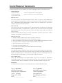
L
EA DETENIDAMENTE LAS SIGUIENTES INSTRUCCIONES DE INSTA-
LACIÓN DEL PRODUCTO.
Este manual contiene información sobre la construcción, installación y fun-
cionamiento de los sistemas fanaticP. Le recomendamos que conserve el
manual para futuras consultas.
Es preferible que la instalación de sistema fanaticP sea realizada por un dis-
tribuidor autorizado Rockford Fosgate. Si prefiere realizar la instalación usted
mismo, asegurese de leer el manual en su totalidad antes de comenzar.
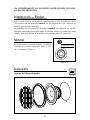
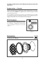
Le mejor interacción entre tweeter y medio se
consigue si no están separados entre si más
de 5 cenimetros (Figura 1).
Montaje del altavoz de medios
no superior a 5cm
Figura 1
INTRODUCCIÓN — ESPAÑOL
MONTAJE
INSTALACIÓN
I
N
S
T
A
L
L
A
T
I
O
N
+ -
+ -

– 11 –
weeter
Ne
g
ativo
c
able Ne
g
ro
)
P
os
itiv
o
(cable Negro con
r
a
y
a Blanca
)
Ne
g
ativo
de Medioran
go
Negativo
T
w
ee
t
e
r
P
os
itiv
o
de A
g
ud
o
P
os
itiv
o
de Medioran
go
(Un canal del
amplificador)
1. Corte el agujero para el medio/woofer.
• Par el 102mm, corte un circulo de 90mm de diámetro
• Par el 133mm, corte un circulo de 114mm de diámetro
• Par el 152mm, corte un circulo de 129mm de diámetro
• Par el 165mm, corte un circulo de 139mm de diámetro
2. Use los anillos de montaje de plástico como plantilla. Marque la posi-
ción de los tornills de anclaje.
3. Quite el anillo y perfore los agujeros con una broca de 3mm.
4. Pase el cable de altavoz a través del agujero.
5. Conecte los cables observando la polaridad. Mantenga los cables aleja-
dos pe partes móviles o cortantes.
6. Monte el anillo de montaje sobre el medio/woofer.
7. Asegure el altavoz en la abertura con los tornillos. Tenga la precaución
de no doblar el marco del altavoz en este proceso.
8. Presione la rejilla en el anillo de montaje.

– 12 –
VEUILLEZ LIRE LES INSTRUCITONS SUIVANTES POUR L'INSTALLA-
TION DE CES PRODUITS.
Ce manuel contient des informations sur les caractéristiques et l'installation
des systèmes fanaticP. Nous vous proposons de garder ce manuel pour
toute référence future.
Nous vous recommandons vivement de faire installaer votre système
punch fanaticP par un dealer agréé Rockford Fosgate. Si vous choisissez
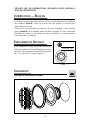
d'installer le système vous même, assurez-vous de lire ce manuel entière-
ment avant de commencer.
Pour bénéficier d'une harmonie maximum
entre le médium et l'aigu l'éloignement entre
ces deux haut-parleurs devrait être de moins
de 5 cm entre les 2 chassis (Figure 1).
Montage du haut-parleur médium
moins de 5cm
Figure 1
INTRODUCTION — FRANÇAIS
EMPLACEMENT DE MONTAGE
INSTALLATION
I
N
S
T
A
L
L
A
T
I
O
N
+ -
+ -

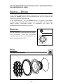
– 13 –
weeter
N
é
g
atif
â
ble noire
)
P
os
itif
(c
b
l
e
n
o
ir
e
r
a
y
é
de blanc
)
N
é
g
atif
du
m
é
d
i
u
m
N
é
gatif
de
l
’
ai
g
u
P
os
itif
de
l
’
aigu
P
os
itif
du
m
é
d
i
u
m
al
de
l
’
amplificateur)
1. Découper un trou adapté au haut-parleur médium/woofer.
• Pour le 102mm, le diamètre du trou est de 90mm
• Pour le 133mm, le diamètre du trou est de 114mm
• Pour le 152mm, le diamètre du trou est de 129mm
• Pour le 165mm, le diamètre du trou est de 139mm
2. Placer l'anneau de montage sur le trou et repérer l'emplacement des
trous des vis.
3. Retirer l'anneau. Percer les trous des vis en utilisant une mèche de 3mm.
4. Faire passer les fils dans le médium/woofer.
5. Connecter les fils au haut-parleur en respectant les polarités. Eloigner les
fils de toute partie tranchante ou mobile du véhicule.
6. Placer l'anneau de montage au-dessus du trou central.
7. Placer le haut-parleur au-dussus du trou central. Visser le haut-parleur
dans son emplacement. Faire attention à ne pas tordre le chassis du
haut-parleur durant cette étape de montage.
8. Mettre la grille dans l'anneau de montage.

– 14 –
DIE FOLGENDE BEDIENUNGSANLEITUNG SOLL IHNEN BEIM EINBAU
EINE HILFESTELLUNG GEBEN.
Diese Bedienungsanleitung enthält Informationen für den Gebrauch und
Einbau des fanaticP Systems. Wir empfehlen, diese auch für Fragen in der
Zukunft sorgfältig aufzubewahren.
Es ist empfehlenswert, sich das fanaticP System von einem Autorisierten
Rockford Fosgate Fachhändler einbauen zu lassen. Sollten Sie den Einbau
jedoch selber vornehmen wollen, so empfehlen wir Ihnen, die
Bedienungsanleitung sorgfälitg zu lesen.
Für das optimale Zusammenspiel von Mittel-
und Hochtöner, sollte der Hochtöner
niemals weiter als 5cm vorn Mitteltöner ent-
fernt montiert werden (Abb. 1).
Montage des Mitteltöners
Abstand max. 5cm
Abb. 1
ENLEITUNG — DEUTSCH
EINBAUORT
EINBAU
I
N
S
T
A
L
L
A
T
I
O
N
+ -
+ -

– 15 –
1. Schneiden Sie die richtige Lochgröbe für den Mitteltöner oder Midbab
aus.
• Für den 102mm, schneiden Sie ein 90mm Ø Loch
• Für den 133mm, schneiden Sie ein 114mm Ø Loch
• Für den 152mm, schneiden Sie ein 129mm Ø Loch
• Für den 165mm, schneiden Sie ein 139mm Ø Loch
2. Setzen Sie den Montagering auf das Loch und markieren Sie die Löcher
für die Schrauben.
3. Nehmen Sie den Ring wieder ab und bohren Sie dann, mit einem
passenden Bohrer, die Schraubenlöcher vor.
4. Führen Sie das Kabel durch das Loch.
5. Schlieben Sie die Lautsprecherkabel an. Kontrollieren Sie, ob die
Polarität stimmt. Stellen Sie sicher, dab das Lautsprecherkabel an keinen
scharfen oder sich bewegenden Teilen anliegt.
6. Plazieren sie den Montagering über dem mitteltöners.
7. Plazieren Sie den Lautsprecher im Loch und befestigen Sie diesen. Seien
Sie dabei sehr vorsichtig, so dab sich der Lautsprecherkorb nicht
verzieht.
8. Drücken Sie das Lautsprechergitter im Montagering fest.
weeter
Min
us
(
Schwarzes Kabel
)
Pl
us
(
Schwarz/We
i
β
β
g
estreiftes Kabel
)
Mitt
e
l
t
ö
n
e
r
Min
us
Hoc
h
t
ö
er
Min
us
Hoc
h
t
ö
n
e
r
Plus
Mitt
e
l
t
ö
n
e
r
Pl
us
(Ein Kanal
des
V
e
r
st
ä
r
kers
)

– 16 –
LEGGERE LE ISTRUZIONI SEGUENTI PRIMA DELL'INSTALLAZIONE DEL
PRODOTTO.
Questo manuale fornisce informazioni sulle caratteristiche e sul instal-
lazione dei sistemi fanaticP. Vi suggeriamo di conservare questo manuale
come riferimento futuro.
Raccomandiamo fortemente che is sistema sia installato dal vostro rivendi-
tore Rockford Fosgate. Se scegliete di procedere con l'installazione da soli,
leggete attentamente tutto il manuale prima di proseguire.
Per ottenere la miglior integrazione tra tweet-
er e midrange, vi suggeriamo di posizionare
i due componenti a meno di 5 cm tra loro
(Figura 1).
Installazione del Midrange
meno di 5 cm
Figura 1
INTRODUZIONE — ITALIANO
POSIZIONAMENTO
INSTALLAZIONE
I
N
S
T
A
L
L
A
T
I
O
N
+ -
+ -

– 17 –
weeter
Ne
g
ativo
P
os
itiv
o
cavo nero/
bianco
)
Ne
g
ativo
Midran
ge
Negativo
T
w
ee
t
e
r
P
os
itiv
o
Tweeter
P
os
itiv
o
Midran
ge
(U ca ale
de
l
l
’
amplificatore
)
1. Practicate un foro del diametro corretto per il midrange/woofer
• 102mm per 90mm
• 133mm per 114mm
• 152mm per 129mm
• 165mm per 139mm
2. Posizionate l'anello della griglia sul foro e segnate la posizione delle viti.
3. Togliete l'anello e forate il pannello con una puna da 3mm.
4. Passate i cavi attraverso il foro.
5. Collegate i cave assicurandovi di osservare la corretta polarità.
Assicuratevi di mantenere i cavi lontano da parti in movimento o strut-
ture taglienti.
6. L'anello della griglia sopra il foro dell midrange.
7. Posizionate l'altoparlante nel foro ed avvitatelo. Assicuratevi di non pie-
gare il cestello dell'altoparlante.
8. Incastrate la griglia sull'anello di fissaggio.
La page charge ...
La page charge ...
La page charge ...
La page charge ...
-
 1
1
-
 2
2
-
 3
3
-
 4
4
-
 5
5
-
 6
6
-
 7
7
-
 8
8
-
 9
9
-
 10
10
-
 11
11
-
 12
12
-
 13
13
-
 14
14
-
 15
15
-
 16
16
-
 17
17
-
 18
18
-
 19
19
-
 20
20
-
 21
21
-
 22
22
-
 23
23
-
 24
24


Rockford Fosgate FNP2414 Manuel utilisateur
- Catégorie
- Haut-parleurs de voiture
- Taper
- Manuel utilisateur
dans d''autres langues
- English: Rockford Fosgate FNP2414 User manual
Documents connexes
-
 Rockford Fosgate Fanatic X FNX2614 Installation & Operation Manual
-
 Rockford Fosgate Fanatic P FNP1614F Operation and Installation Manual
-
 Rockford Fosgate Punch FNX2405 Manuel utilisateur
-
 Rockford Fosgate Fanatic Q FNQ1414 Operation & Installation
-
 Rockford Fosgate Fanatic FNQ2414 Operation & Installation
-
 Rockford Fosgate Punch Power RFR-1414 Operating & Installation Manual
-
Rockford Fosgate 3-Way FNQ3146 Manuel utilisateur
-
 Rockford Fosgate Punch RFA-614 Manuel utilisateur
-
 Rockford Fosgate P1692S Manuel utilisateur
-
Rockford Fosgate Punch P1675-S Installation & Operation Manual


