Bosch NGM8058UC Manuel utilisateur
- Catégorie
- Cuisinières
- Taper
- Manuel utilisateur


2
Table of contents
1 IMPORTANT SAFETY INSTRUCTIONS.....................3
1.1 Safety definitions........................................................4
1.2 General information....................................................4
1.3 General safety instructions.........................................4
1.4 Appliance handling safety ..........................................4
1.5 Safety codes and standards.......................................4
1.6 Electrical safety..........................................................5
1.7 Gas safety..................................................................5
1.8 Propane gas installation.............................................6
1.9 Ventilation recommendations.....................................6
1.10 High altitude installation ...........................................6
1.11 State of California Proposition 65 Warnings .............6
2 Before you begin........................................................7
2.1 Parts included ............................................................7
2.2 Tools and parts needed .............................................7
2.3 General requirements ................................................7
2.4 Cabinet requirements.................................................7
2.5 Countertop requirements ...........................................7
2.6 Gas requirements ......................................................8
2.7 Electrical requirements...............................................8
3 Prepare installation space.........................................8
3.1 Dimensions for 30" cooktops......................................8
3.2 Dimensions for 36" cooktops......................................8
4 Installation procedure ...............................................9
4.1 Preparing the cooktop................................................9
4.2 Installing the pressure regulator .................................9
4.3 Securing the cooktop to the countertop....................10
4.4 Connection overview................................................10
4.5 Connecting the gas supply line ................................10
4.6 Connecting the electrical supply...............................11
4.7 Assembling the burner parts ....................................11
4.8 OptiSim® feature .....................................................12
4.9 Installing the burner grates.......................................12
4.10 Checking the installation ........................................12
5 Conversion to LP gas ..............................................13
5.1 Converting the pressure regulator............................13
5.2 Replacing the orifices...............................................14
5.3 Adjusting the gas valves ..........................................14
5.4 Burner chart .............................................................15
6 Customer Service ....................................................15
6.1 Model number (E-Nr.) and production number
(FD) .........................................................................16
6.2 Rating plate location.................................................16

en-us
3
Read all instructions carefully before use. These precautions will reduce the risk of electrical shock, fire and injury to
persons. When using kitchen appliances, basic safety precautions must be followed including those in the following
pages.
IMPORTANT SAFETY INSTRUCTIONS
READ AND SAVE THESE INSTRUCTIONS

en-us
4
1.1 Safety definitions
Here you can find explanations of the safety signal words
used in this manual.
WARNING
This indicates that death or serious injuries may occur as
a result of non-observance of this warning.
CAUTION
This indicates that minor or moderate injuries may occur
as a result of non-observance of this warning.
NOTICE:
This indicates that damage to the appliance or property
may occur as a result of non-compliance with this advi-
sory.
Note:This alerts you to important information and/or tips.
1.2 General information
¡Read this manual carefully.
¡Keep the manual and the product information in a safe
place for future reference or for the next owner.
¡Do not connect the appliance if it has been damaged in
transit.
1.3 General safety instructions
IMPORTANT: THE APPLIANCE MUST BE INSTALLED
BY A QUALIFIED INSTALLER.
IMPORTANT: SAVE THESE INSTRUCTIONS FOR THE
LOCAL ELECTRICAL INSPECTOR’S USE.
OWNER: PLEASE RETAIN THESE INSTRUCTIONS
FOR FUTURE REFERENCE.
INSTALLER: LEAVE THESE INSTRUCTIONS WITH
THE APPLIANCE AFTER INSTALLATION IS COM-
PLETE.
Examine the appliance after unpacking it. In the event of
transport damage, do not plug it in.
WARNING
If the information in this manual is not followed exactly, fire
or shock may result causing property damage or personal
injury.
Do not repair, replace or remove any part of the appliance
unless specifically recommended in the manuals. Im-
proper installation, service or maintenance can cause in-
jury or property damage.
▶Refer to this manual for guidance.
▶All other servicing should be done by an authorized ser-
vice provider.
Disconnect electrical and gas supply before servicing.
When installing a cooktop over a single oven, be sure to
follow the instructions in both the oven's and the cooktop's
installation manuals.
▶You can find a list of approved combinations of cooktop
and oven in the Approved Combination Matrix of your
cooktop, or you can contact Customer Service for the
latest list of approved combinations. Do not try to install
your cooktop over any oven that is not stated in that list.
Never modify or alter the construction of the appliance.
The appliance should only be used if installed by a quali-
fied technician in accordance with these installation in-
structions. The manufacturer is not responsible for any
damage resulting from incorrect installation.
To eliminate the risk of burns or fire by reaching over
heated surface units, cabinet storage space located above
the surface units should be avoided.
▶If cabinet storage is to be provided, the risk can be re-
duced by installing a hood that projects horizontally a
minimum of 5" (127mm) beyond the bottom of the cabi-
net.
▶Verify that cabinets above the cooktop are a maximum
of 13" (330mm) deep.
WARNING
Remove all tape and packaging before using the appli-
ance.
▶Destroy the packaging after unpacking the appliance.
▶Dispose of packaging in an environmentally responsible
manner.
▶Never allow children to play with packaging material.
▶Store small parts safely as they can be a choke hazard.
1.4 Appliance handling safety
WARNING
Hidden surfaces may have sharp edges.
▶Use caution when reaching behind or under appliance.
1.5 Safety codes and standards
This appliance complies with the latest version of one or
more of the following standards:
¡ANSI Z21.1 / CSA 1.1 Household Cooking Gas Appli-
ances
IMPORTANT SAFETY INSTRUCTIONS
READ AND SAVE THESE INSTRUCTIONS

en-us
5
¡Installation must conform with local codes or, in the ab-
sence of local codes, with the National Fuel Gas Code,
ANSI Z223.1/NFPA 54 or, in Canada, the Natural Gas
and Propane Installation Code, CSA B149.1.
It is the responsibility of the owner and the installer to de-
termine if additional requirements and/or standards apply
to specific installations.
1.6 Electrical safety
¡Installer - show the owner the location of the circuit
breaker or fuse. Mark it for easy reference.
¡If required by the National Electrical Code (or Canadian
Electrical Code), this appliance must be installed on a
separate branch circuit.
¡Local codes vary. The installer is responsible for ensur-
ing that the installation, connections, and grounding
comply with all applicable codes. The manufacturer is
not responsible for any issues associated with the im-
proper installation of this product.
¡The appliance must be electrically grounded in accor-
dance with local codes or, in the absence of local
codes, with the National Electrical Code, NFPA 70 lat-
est edition or, in Canada, the Canadian Electric Code,
CSA C22.1-02.
¡Be sure your appliance is properly installed and
grounded by a qualified technician. Installation, electri-
cal connections and grounding must comply with all ap-
plicable codes.
¡Do not use an extension cord.
¡Do not use an adapter.
¡Refer to the rating plate for more information.
→
"Rating plate location", Page16
WARNING
Before installing, turn power OFF at the service panel.
▶Lock service panel to prevent power from being turned
ON accidentally.
For appliances equipped with a cord and plug, do not cut
or remove the ground prong.
▶It must be plugged into a matching grounding type re-
ceptacle to avoid electrical shock.
▶If there is any doubt as to whether the wall receptacle is
properly grounded, the customer should have it
checked by a qualified electrician.
GROUNDING INSTRUCTIONS
▶This appliance must be grounded.
▶Grounding reduces the risk of electric shock by provid-
ing a safe pathway for electric current in the event of a
short circuit.
▶Be sure your appliance is properly installed and
grounded by a qualified technician.
▶Installation, electrical connections and grounding must
comply with all applicable codes.
Before you plug in an electrical cord, be sure all controls
are in the OFF position.
Before you turn on power supply, make sure all controls
are in the OFF position.
1.7 Gas safety
Requirements for gas supply:
¡Install a gas shutoff valve near the appliance. It must be
easily accessible in an emergency.
¡Leak testing must be conducted by the installer accord-
ing to the instructions in this manual.
¡The appliance and its individual shutoff valve must be
disconnected from the gas supply piping system during
any pressure testing at pressures in excess of ½psi
(3.5kPa).
¡The appliance must be isolated from the gas supply
piping system by closing its individual manual shutoff
valve during any pressure testing of the gas supply pip-
ing system at test pressures equal to or less than ½psi
(3.5kPa).
¡The minimum supply pressure must be 1" water column
above the manifold pressure printed on the rating label.
The maximum supply pressure must not exceed 14.0
inches water column (34.9Millibars).
¡A metal flex line or fixed metal pipe shall be used to
connect gas to the appliance. If a metal gas line cannot
be used, consult your local certified electrician or local
electric codes for proper grounding.
IMPORTANT SAFETY NOTICE: Burning gas cooking fuel
generates some by-products which are on the list of sub-
stances which are known by the State of California to
cause cancer or reproductive harm. To minimize exposure
to these substances, always operate this unit according to
the instructions contained in this booklet and provide good
ventilation.
IMPORTANT SAFETY INSTRUCTIONS
READ AND SAVE THESE INSTRUCTIONS

en-us
6
1.8 Propane gas installation
¡The propane gas tank must be equipped with its own
high pressure regulator. In addition, the regulator sup-
plied with this unit must also be used.
¡The appliance is shipped from the factory for use with
natural gas. It must be converted for use with propane.
A qualified technician or certified installer must do the
conversion.
¡For use with propane the appliance must be converted
per the LP conversion instructions.
→
"Conversion to LP gas", Page13
For Massachusetts installations
¡Installation must be performed by a qualified or li-
censed contractor, plumber or gas fitter qualified or li-
censed by the state, province or region where this ap-
pliance is being installed.
¡Shut-off valve must be a “T” handle gas cock.
¡Flexible gas connector must not be longer than
36inches.
Installer - show the owner where the gas shut-off valve is
located.
1.9 Ventilation recommendations
We strongly recommend the installation of a ventilation
hood above this appliance.
The hood must be installed according to instructions fur-
nished with the hood.
WARNING
The appliance should not be installed with a ventilation
system that blows air downward toward the burners. This
type of ventilation system may cause ignition and combus-
tion problems with the gas cooking appliance resulting in
personal injury or unintended operation.
1.10 High altitude installation
This appliance has been tested for operation up to an alti-
tude of 10,100ft (3,080m) elevation above sea level.
For altitudes above 2,000ft (610m) elevation above sea
level, burner flame adjustments may be necessary.
Burners should be checked at the lowest setting, if the
flame is not stable the simmer should be increased until
the flame is stable. This can be done by adjusting the by-
pass screw in the valve. If flame performance is satisfac-
tory, adjustment will not be required. It is required that a
certified professional make the high altitude adjustments
during installation.
1.11 State of California Proposition 65
Warnings
This product may contain a chemical known to the State
of California, which can cause cancer or reproductive
harm. Therefore, the packaging of your product may bear
the following label as required by California:
IMPORTANT SAFETY INSTRUCTIONS
READ AND SAVE THESE INSTRUCTIONS

Before you begin en-us
7
Before you begin
2 Before you begin
Before you begin
Read these instructions before you begin to install your
appliance.
2.1 Parts included
After unpacking all the parts, check for any damage in
transit and for completeness of delivery.
¡Cooktop
¡Foam tape
¡Hold-down brackets (4)
¡Screws, #10-32 x 2½" (63.8mm), (4)
¡Sheet metal screws, #8 x 3/8" (9.5mm), (4)
¡Washers (4)
¡Burner grates (3)
¡Burners (5)
¡Burner caps (6)
¡Pressure regulator
¡LP gas conversion kit
2.2 Tools and parts needed
Prepare these tools and accessories before you start to in-
stall your appliance.
¡Pencil
¡Measuring tape
¡Cross head screwdriver
¡Drill with bit 1/4" (6mm)
¡Jigsaw
¡Adjustable wrench
¡Teflon® tape - gas rated
¡Flathead screwdriver, 1/8"
Note:Additional materials may be necessary for installa-
tion in solid surface countertops. Contact the countertop
manufacturer.
2.3 General requirements
Ensure that the following requirements are met when plan-
ning the installation of your appliance.
¡Plan the installation of the unit so that the power cord,
gas shut-off valve and gas pressure regulator are ac-
cessible from the front of the cabinet.
¡Make sure the gas supply line does not interfere with
the back of the appliance.
¡The cabinet in which the cooktop is installed must be
properly secured, level and stable.
¡Any laminated coverings and glue on cabinets next to
the cooktop must be made of non-flammable and heat
resistant materials.
¡This appliance cannot be installed above refrigerators,
washing machines, dishwashers or similar.
¡If an oven is installed underneath the cooktop, the thick-
ness specified for the countertop surface may exceed
the minimum thickness stated in these instructions. Ob-
serve the information in the oven's installation instruc-
tions.
2.4 Cabinet requirements
Ensure that the cabinetry at the installation location meets
the requirements for a safe installation.
The minimum spaces that must be maintained when in-
stalling the gas cooktop shall be the following:
a min. 13" (330mm)
for installation next to oven min. 13" (330mm)
b min. 13" (330mm)
for installation next to oven min. 13" (330mm)
c min. 30" (762mm) clearance between the top of
the cooking surface and the bottom of combustible
constructions
d min 3" (76mm);
for installation in kitchen islands, min. 4" (100mm)
e For 30" cooktops:
min. 30" (760mm) centered over cooktop
e For 36" cooktops:
min. 36" (914mm) centered over cooktop
f min. 18" (458mm)
g max. 13" (330mm)
h min. 1¾" (48mm);
for installation in kitchen islands, min. 4" (100mm)
2.5 Countertop requirements
Ensure that the countertop into which the cooktop is to be
installed meets these requirements for a safe installation.
WARNING
To reduce the risk of ignition of surrounding combustible
materials, install at least 13" (330mm) from both sidewalls
and at least 3" (76mm) from the rear wall.
¡The countertop must be level and horizontal.
¡The stability of the countertop must be maintained after
the cut-out has been made.
¡Solid surface countertops often require special installa-
tions. For example, heat-reflective tape and rounded
corners may be necessary.
¡Contact the countertop manufacturer for instructions
specific to your countertop.

en-us Prepare installation space
8
2.6 Gas requirements
Ensure that the requirements for the gas supply are met.
The cooktop is shipped from the factory for use with natu-
ral gas. For use with LP conversion, a certified technician
or installer must do the conversion.
Supply pressure:
¡Natural Gas: 7 inches water column (17.4 Millibars)
¡Propane Gas: 11 inches water column (27.4 Millibars)
¡The propane gas tank must be equipped with its own
high pressure regulator in addition to the pressure regu-
lator supplied with this unit.
2.7 Electrical requirements
Ensure that the following electrical requirements are met.
CAUTION
Do not use an extension cord with this appliance.
¡This appliance requires a 60Hz, 15Amp, 120V/AC
connection.
¡The appliance is equipped with a 40" (1000mm) power
cord.
¡The power connection must remain accessible from the
front of the cabinet after the installation is complete.
Prepare installation space
3 Prepare installation space
Prepare installation space
Create the cutout in the countertop according to the in-
structions.
General countertop requirements:
¡The angle of the cut surface to the countertop must be
90°.
¡With multi-layered countertops, secure strips laterally in
the cutout if necessary.
¡After creating the cutout, remove all shavings.
¡Seal the cut surfaces in a heat- and water-resistant
manner.
¡If there is no oven beneath the cooktop, install a non-
combustible floor with a 3/8" (10mm) space between
the floor and the bottom of the cooktop. The distance
from the intermediate floor to the power supply connec-
tion for the appliance must be at least 3/8" (10mm).
¡Observe the minimum distance between device under-
side and cabinet surfaces of ⅜" (10mm).
3.1 Dimensions for 30" cooktops
Refer to these measurements for the models stated here.
¡NGM8058UC
¡NGM8048UC
(60)
2⅜"
min. ¾" (19)
max. 2" (50)
*For installation in a kitchen island.
3.2 Dimensions for 36" cooktops
Refer to these measurements for the models stated here.
¡NGM8658UC
¡NGM8648UC
(60)
2⅜"
min. ¾" (19)
max. 2" (50)

Installation procedure en-us
9
*For installation in a kitchen island.
Installation procedure
4 Installation procedure
Installation procedure
Follow these instructions to install the cooktop into the
countertop.
CAUTION
Sharp edges.
▶Use protective gloves when installing the appliance.
CAUTION
The appliance is heavy.
▶It is recommended that two people install this appliance.
4.1 Preparing the cooktop
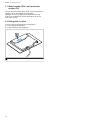
1. Place the cooktop face down on a soft and stable sur-
face.
2. Apply the included foam sealing tape around the edges
of the underside of the appliance.
3. Attach the hold-down brackets to the underside of the
cooktop with the provided short screws and washers.
Do not tighten the screws.
4.2 Installing the pressure regulator
WARNING
Do not attempt any adjustment of the pressure regulator,
except when converting to propane. Adjustments could
lead to leaks or cause incorrect gas pressure to the appli-
ance.
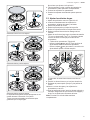
1. Identify the parts of the pressure regulator.
a Appliance manifold connection
b Conversion nut
c Pressure regulator
2. Install the pressure regulator supplied with the cooktop
to the appliance manifold connection. Apply Teflon®
tape on the threads of the manifold pipe.
3. Turn the pressure regulator to hand tighten plus ¼turn,
not exceeding 1turn for alignment.
aWhen the regulator is securely installed on the manifold
pipe, the conversion nut will be easily accessible.
4. WARNING Make sure the used gas connection
line is not connected to the gas supply, before carrying
out the following steps.
Connect a ½" metal flex gas line or fixed metal pipe
connection to the pressure regulator. Always install a
new gas connection.

en-us Installation procedure
10
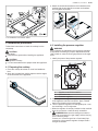
4.3 Securing the cooktop to the countertop
The cooktop must be secured from below using the hold-
down brackets provided.
WARNING
Before installing, turn power OFF at the service panel.
▶Lock service panel to prevent power from being turned
ON accidentally.
1. Rotate the hold-down brackets so that the appliance
can be placed in the cutout.
2. CAUTION Do not let the cooktop drop into place.
▶Make sure that the cooktop is supported along the
edges when carefully placing it into the cutout.
Turn the cooktop over carefully making sure not to dam-
age the pressure regulator and gas line. Place the cook-
top carefully into the countertop cutout, pushing it to-
wards the front of the cutout. Make sure the cooktop is
centered between the left and right edges of the cutout.
3. Insert the 2½" clamping screws into the hold-down
bracket and secure the cooktop to the countertop .
Protect delicate countertops by placing a wooden disk
underneath. Tighten the screws to the cooktop .
Note:Do not use silicone to glue the cooktop to the
countertop surface.
4.4 Connection overview
Refer to this illustration for the location of the gas and
electric connection of the appliance.
a Cooktop rough-in box
b Arrow on pressure regulator, shows the direction of
gas flow
c Pressure regulator
d ½" female pipe threads
e Metal flex gas line
f Power cord (40"/1m)
g 120V receptacle
h Gas cut-off valve
i Gas supply line connection fitting
j Floor
4.5 Connecting the gas supply line
Note
Ensure the following requirements are met before you try
to connect the appliance to the gas supply:
¡The appliance is shipped from the factory for use with
natural gas. If you want to use propane gas it must be
converted. A qualified technician or installer must do the
conversion.
¡Before connecting the appliance, please check whether
the local connection conditions such as gas type and
gas pressure match the appliance settings.
¡Make sure the gas supply is turned off at the manual
shutoff valve before connecting the appliance.
¡The gas connection must be in a location that permits
access to the manual shut-off valve and which, if appli-
cable, is visible after opening the door of the cabinet.
¡The metal flex gas line must not come into contact with
moving parts of the fitted unit (e.g. drawers) or be laid in
areas where it could become trapped or damaged.
¡The metal flex gas line must not come into contact with
a cooktop, oven, dishwasher, refrigerator, washing ma-
chine, hot water pipe, radiator or any other appliance in-
stalled in the vicinity of the gas cooktop.
¡The metal flex gas line must not be subject to rubbing,
vibrations, kinking or any other kind of deformation. It
should be checked along its entire length with the cook-
top in the installation position.

Installation procedure en-us
11
▶Connect the metal flex gas line or fixed metal pipe con-
nection from the cooktop pressure regulator to the man-
ual shut-off valve.
Checking the gas line for leaks
Check the gas supply line connections for leaks using a
soap solution or non-corrosive leak detection fluid. Do not
use a flame of any sort.
Note
Important notes for gas connection:
¡The appliance and its individual shutoff valve must be
disconnected from the gas supply piping system during
any pressure testing at pressures in excess of ½psi
(3.5kPa).
¡The appliance must be isolated from the gas supply pip-
ing system by closing its individual manual shutoff valve
during any pressure testing of the gas supply piping
system at test pressures equal to or less than ½psi
(3.5kPa).
1. Turn on gas.
2. Apply a soap solution or non-corrosive leak detection
fluid to all joints and fittings in the gas connection be-
tween the shut-off valve and the cooktop. Also check
gas fittings and joints in the cooktop if the connections
may have been disturbed during installation.
aBubbles appearing around fittings and connections indi-
cate a leak.
3. If a leak appears, turn off the supply line gas shut-off
valve and tighten the connections.
4. Retest for leaks by turning on the supply line gas shutoff
valve.
aWhen the leak check is complete and no bubbles ap-
pear, the test is complete.
5. Wipe off all soap solution or detection fluid residue.
4.6 Connecting the electrical supply
CAUTION
Before you plug in the electrical cord, make sure that the
gas shut-off valve and all burner controls are in the OFF
position.
▶Connect the plug of the electrical cord to a grounded
power outlet. The outlet must be accessible after the in-
stallation of the appliance is complete.
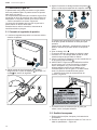
4.7 Assembling the burner parts
The burner parts must be properly placed for the cooktop
to function properly.
Note
If the burner parts are not properly placed, one or more of
the following problems may occur:
¡The burner flames are too high.
¡Flames shoot out of the burners.
¡The burners do not ignite.
¡The burner flames light unevenly.
¡The burners emit gas odor.
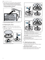
1. Assemble the burner parts according to the illustration.
1
2
3
4
4
3
2
1
1
Burner cap
2
Burner base
3
Thermocouple
4
Igniter
Make sure that the prongs of the burner cap fit snugly
into the groove of the burner base.
2. Check to make sure that there is no gap between the
burner parts. You may gently try to move the burner
parts from side to side to check if they are properly
seated.

en-us Installation procedure
12
4.8 OptiSim® feature
The OptiSim® burner cap has been designed to work with
the small burner at the front left position of the cooktop. It
is used to provide optimal simmering for delicate sauces
while minimizing the risk of scorching.
Installing the OptiSim® burner cap
▶Place the burner cap on the burner base, so that the
lower protrusion locks in place in the center of the
burner base.
aWhen properly installed the OptiSim® burner cap will
extend beyond the burner base and raised surface.
4.9 Installing the burner grates
WARNING
Improperly positioned grates can cause flare-ups.
▶Position all grates properly on the cooktop whenever
the cooktop is in use to properly support pots and avoid
spills.
▶Make sure each of the four feet of the grates is placed
into the corresponding dimples on the cooktop surface.
▶Do not use a grate if the rubber feet are missing or
damaged.
1. NGM8058UC, NGM8048UC
2. NGM8658UC, NGM8648UC
4.10 Checking the installation
Check if your unit is working properly after you have com-
pleted the installation steps.
WARNING
Before you turn on power supply, make sure all controls
are in the OFF position.
Requirement:The burner caps are properly positioned.
1. Verify that the electric igniters are working.
2. Check the flame characteristics.
The flame should be blue with a minimal yellow tip on
the outer cone.
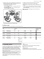
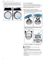
Flame characteristics
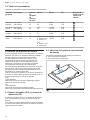
The color of the flame tells you if the gas supply is properly adjusted.
Note:Allow the appliance to operate for 4 to 5minutes before evaluating the flame. Some yellow streaking is normal dur-
ing the initial startup.

Conversion to LP gas en-us
13
Flame Image Measure
Completely or mostly
yellow Verify that the regulator is set for the correct fuel. Retest af-
ter adjustment.
Yellow tips on outer
cone Normal for LP gas
Soft blue Normal for natural gas
Conversion to LP gas
5 Conversion to LP gas
Conversion to LP gas
Your appliance is equipped for use with natural gas on de-
livery. It can be changed to LP gas supply.
The components required for conversion to LP Gas are
contained in the conversion kit included with this appli-
ance, or are available from Customer Service.
→
"Customer Service", Page15
Only a licensed specialist is authorized to switch the appli-
ance to another gas type.
Before carrying out the conversion, turn off the electricity
and gas supply.
5.1 Converting the pressure regulator
1. Locate the pressure regulator on the bottom right end of
the appliance.
2. Remove the hexagon shaped cap from the regulator.
Make sure not to dislodge the gasket on the cap or
the spring inside the regulator.
3. Grasp the plastic button stem firmly and pull it force-
fully from the metal cap .
The stem snaps snugly into an indent in the cap and
may require a strong pull to remove.
It may be helpful to gently “rock” the plastic stem while
pulling it from the metal cap.
4. Rotate the stem 180° .
aThe button end of the stem is away from the cap.
aThe letters “LP” on the stem are upside down when the
cap is set flat on its head.
5. Snap the stem back in place in this position inserting it
into the indent in the metal cap .

en-us Conversion to LP gas
14
6. IMPORTANT: Attach the metallic sticker included with
the conversion kit to the bottom of the appliance as
shown. This sticker provides notice that the appliance
has been converted for use with LP gas. It should be lo-
cated near the appliance rating plate.
→
"Rating plate location", Page16
7. If you change the type of gas back to natural gas at a
later point, remove the sticker.
5.2 Replacing the orifices
1. Remove all burner grates, burner caps and burner
bases.
2. Replace the orifices with a 7mm socket wrench. See
burner chart →
Page15
.
Normal burner with one orifice
Double burner, first orifice
Double burner, second orifice
It is important to make sure that the orifices do not be-
come detached during removal or fastening.
They must be properly tightened to ensure that there
are no leaks.
The primary air does not have to be adjusted.
3. Fasten the orifices and replace the burner caps to the
corresponding burners.
4. Put the burner grates in place.
5. Save the orifices removed from the appliance for future
use.
5.3 Adjusting the gas valves
1. Turn the control knobs to position off.
2. Carefully lift off the burner grates, remove the burner
caps and the burner bases.
3. Pull off the control knobs.
4. Remove the main top from the cooktop.
5. Remove the electronics pack from the control panel.
6. Remove the white disks from the valve stems.

Customer Service en-us
15
7. Adjust the black T10 star head setting screw with a T10
star head screwdriver. Refer to the burner chart for the
correct setting of the setting screws (M).
→
"Burner chart", Page15
‒Use setting for LP Gas. The setting screws must
be tightened properly.
‒Use setting for natural gas. The setting screws
must finish flush with the fitting.
The dual-flame burner has 2setting screws.
8. Replace the white disks and the electronics pack.
9. Reinstall the main top and the control knobs.
10. Place the burner caps and the burner grates back in po-
sition.
11. Turn the control knob between the highest and lowest
setting. Make sure the flame does not go out and there
are no flashbacks.
Note:In the event of damage, the valve must be com-
pletely replaced.
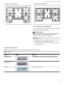
5.4 Burner chart
Refer to this overview for specifications of the individual burners.
Burner
cap Gas type Pressure
in inch
wc
Orifice BTU/h kW M (valve ad-
justment screw
setting)
Small
burner Natural gas
Propane gas 6
10 77
54 3,400
3,400 1.00
1.00
Large
burner Natural gas
Propane gas 6
10 133
93 10,300
10,300 3.00
3.00
Medium
burner Natural gas
Propane gas 6
10 102
71 6,000
6,000 1.75
1.75
Dual
burner Natural gas
Propane gas 6
10 NG:
¡outer: 161
¡inner: 74
PG:
¡outer: 105
¡inner: 39
17,000
14,500 5.00
4.30
Customer Service
6 Customer Service
Customer Service
If you have any questions on use, are unable to eliminate
an issue in the appliance yourself, or the appliance needs
to be repaired, please contact our Customer Service.
With any warranty repair, we will make sure your appli-
ance is repaired by an authorized service provider using
genuine replacement parts. We use only genuine replace-
ment parts for all repairs.
Detailed information on the warranty period and terms of
warranty can be found in the Statement of Limited Product
Warranty, from your retailer, or on our website.
If you contact the Customer Service, you will need the
model number (E-Nr.) and the production number (FD) of
your appliance.
USA:
1-800-944-2904
www.bosch-home.com/us/owner-support/get-support
www.bosch-home.com/us/shop
CA:
1-800-944-2904
www.bosch-home.ca/en/service/get-support
www.bosch-home.ca/en/service/cleaners-and-accessories

en-us Customer Service
16
6.1 Model number (E-Nr.) and production
number (FD)
You can find the model number (E-Nr.) and the production
number (FD) on the appliance's rating plate.
Making a note of your appliance's details and the Cus-
tomer Service telephone number will enable you to find
them again quickly.
6.2 Rating plate location
You can find the rating plate of your appliance:
¡On the appliance certificate.
¡on the underside of the appliance
Rating plate

fr-ca
17
Table des matières
1 IMPORTANTES CONSIGNES DE SÉCURITÉ .........18
1.1 Définitions des termes de sécurité ...........................19
1.2 Indications générales ...............................................19
1.3 Consignes générales de sécurité .............................19
1.4 Manipulation sécuritaire des appareils .....................20
1.5 Codes et normes de sécurité ...................................20
1.6 Sécurité électrique ...................................................20
1.7 Sécurité des gaz ......................................................21
1.8 Installation au gaz propane ......................................21
1.9 Recommandations de ventilation .............................21
1.10 Installation à haute altitude.....................................21
1.11 Mises en garde conformément à la proposition
65 de l'État de Californie ........................................22
2 Avant de commencer...............................................23
2.1 Pièces incluses ........................................................23
2.2 Outils et pièces nécessaires.....................................23
2.3 Conditions générales ...............................................23
2.4 Exigences concernant les armoires..........................23
2.5 Exigences du comptoir.............................................23
2.6 Exigences en matière de gaz ...................................24
2.7 Exigences électriques ..............................................24
3 Préparation préalable au montage .........................24
3.1 Dimensions de la découpe pour tables de cuisson
de 30po...................................................................24
3.2 Dimensions de la découpe pour tables de cuisson
de 36po...................................................................24
4 Procédure d’installation ..........................................25
4.1 Préparation de la table de cuisson ...........................25
4.2 Installation du régulateur de pression.......................25
4.3 Fixation de la table de cuisson au comptoir..............26
4.4 Aperçu de la connexion............................................26
4.5 Raccordement de la conduite d’alimentation en
gaz...........................................................................27
4.6 Connexion de l'alimentation électrique .....................27
4.7 Assemblage des pièces du brûleur ..........................27
4.8 OptiSim® fonctionnalité............................................28
4.9 Installation des grilles de brûleur..............................28
4.10 Inspecter l’installation.............................................29
5 Conversion au gaz LP..............................................30
5.1 Conversion du régulateur de pression......................30
5.2 Remplacement des orifices......................................30
5.3 Ajustement des soupapes de gaz ............................31
5.4 Tableau des brûleurs ...............................................32
6 Service à la clientèle................................................32
6.1 Numéro de modèle (E-Nr.) et numéro de
fabrication (FD) ........................................................32
6.2 Emplacement de la plaque signalétique...................32

fr-ca
18
Lisez toutes les instructions attentivement avant l’utilisation. Ces précautions réduiront le risque d’électrocution,
d’incendie et de blessure pour les personnes utilisant l’appareil. Lorsque vous utilisez des appareils électroménagers,
il importe de suivre les précautions de sécurité de base, y compris celles indiquées dans les pages suivantes.
IMPORTANTES CONSIGNES DE SÉCURITÉ
LIRE ET CONSERVER CES INSTRUCTIONS

fr-ca
19
1.1 Définitions des termes de sécurité
Vous trouverez ici des explications sur les mots de
signalisation de sécurité utilisés dans ce manuel.
AVERTISSEMENT
Signale un risque de mort ou de blessure grave si
l’avertissement n’est pas respecté.
MISE EN GARDE
Signale un risque de blessures mineures ou modérées si
l’avertissement n’est pas respecté.
AVIS :
Ceci indique que la non-conformité à cet avis de sécurité
peut entraîner des dégâts matériels ou endommager
l'appareil.
Remarque:Ceci vous signale des informations et/ou
indications importantes.
1.2 Indications générales
¡Lisez attentivement cette notice.
¡Veuillez conserver la notice et les renseignements sur
le produit en vue d’une réutilisation ultérieure ou pour
un futur nouveau propriétaire.
¡Ne branchez pas l’appareil si ce dernier a été
endommagé durant le transport.
1.3 Consignes générales de sécurité
IMPORTANT: L'APPAREIL DOIT ÊTRE INSTALLÉ PAR
UN INSTALLATEUR QUALIFIÉ.
IMPORTANT: CONSERVEZ CES INSTRUCTIONS
POUR L’UTILISATION DE L’INSPECTEUR
ÉLECTRIQUE LOCAL.
PROPRIÉTAIRE: VEUILLEZ CONSERVER CES
INSTRUCTIONS POUR RÉFÉRENCE FUTURE.
INSTALLATEUR: LAISSEZ CES INSTRUCTIONS AVEC
L'APPAREIL UNE FOIS L'INSTALLATION COMPLÈTE.
Examinez l'appareil après l'avoir déballé. En cas de
dommage en cours de transport, ne branchez pas
l'appareil.
AVERTISSEMENT
Si les consignes du présent manuel ne sont pas suivies à
la lettre, il y a un risque d’incendie ou d’électrocution
pouvant entraîner des dommages matériels ou des
blessures.
Ne pas réparer, remplacer ni retirer toute pièce de
l’électroménager à moins que cela ne soit spécifiquement
recommandé par les manuels. L’installation, les
réparations ou l’entretien inadéquats pourraient causer
des blessures ou des dégâts matériels.
▶Consulter ce manuel pour les directives d’utilisation.
▶Toutes les autres réparations doivent être effectuées
par un prestataire de services agréé.
Couper l’alimentation électrique et de gaz avant toute
réparation.
Lorsque vous installez une table de cuisson sur un seul
four, veillez à suivre les instructions des manuels
d'installation du four et de la table de cuisson.
▶Vous pouvez trouver une liste des combinaisons
approuvées de table de cuisson et de four dans la
matrice de combinaisons approuvées de votre table de
cuisson, ou vous pouvez contacter le service clientèle
pour obtenir la dernière liste des combinaisons
approuvées. Ne pas essayer d'installer la table de
cuisson au-dessus de n'importe quel four non énuméré
dans cette liste.
Ne jamais modifier ni altérer la structure de l’appareil
électroménager.
Utilisez uniquement l’appareil électroménager s’il a été
installé par un technicien qualifié conformément aux
présentes instructions d’installation. Le fabricant ne peut
pas être tenu responsable de tous dommages causés par
une installation inadéquate.
Pour éliminer le risque de brûlure ou d'incendie lorsque
vous vous étirez au-dessus des surfaces chauffantes de
l'électroménager, il faut éviter d'installer des armoires de
rangement au-dessus de la surface de l'électroménager.
▶Si une armoire de rangement est installé, il est possible
de réduire le risque en installant une hotte qui dépasse
(horizontalement) d'au moins 5po (127mm) le bord du
fond de l'armoire.
▶Vérifier que la profondeur des armoires au-dessus de la
table de cuisson est au maximum de 13po (330mm).
AVERTISSEMENT
Retirer tout le ruban adhésif et l'emballage avant d'utiliser
l'électroménager.
▶Jetez l'emballage après avoir déballé l'électroménager.
▶Éliminez l'emballage d'une manière respectueuse de
l'environnement.
▶Ne laissez jamais les enfants jouer avec le matériel
d’emballage.
IMPORTANTES CONSIGNES DE SÉCURITÉ
LIRE ET CONSERVER CES INSTRUCTIONS

fr-ca
20
▶Conservez les pièces de petite taille dans un endroit
sûr, car elles peuvent être avalées facilement.
1.4 Manipulation sécuritaire des
appareils
AVERTISSEMENT
Certaines surfaces cachées peuvent avoir des
rebords tranchants.
▶Redoubler de vigilance quand vous passez la main
derrière ou sous l'appareil électroménager.
1.5 Codes et normes de sécurité
Cet appareil est conforme aux plus récentes versions de
l'une ou plus des normes suivantes:
¡ANSIZ21.1/CSA1.1, Appareils électroménagers pour
la cuisson à gaz
¡L’installation doit être conforme aux codes locaux ou,
en l’absence de tels codes, au National Fuel Gas Code
ANSIZ223.1/NFPA54 ou, au Canada, au code
national CSAB149.1 d’installation du gaz naturel et du
propane.
Il est de la responsabilité du propriétaire et de l'installateur
de déterminer si des exigences et/ou des normes
supplémentaires s'appliquent à des installations
spécifiques.
1.6 Sécurité électrique
¡Installateur - indiquez au propriétaire l’emplacement
du disjoncteur ou du fusible. Identifiez sa position pour
pouvoir le retrouver facilement.
¡S’il y a lieu, conformément au Code national de
l’électricit (ou au Code canadien de l’électricité), cet
appareil doit être installé sur un circuit de dérivation
séparé.
¡Les codes locaux peuvent varier. L'installateur est
responsable de s'assurer que l'installation, les
connexions et la mise à la terre sont conformes à tous
les codes applicables. Le fabricant n'est pas
responsable des problèmes associés à une mauvaise
installation de ce produit.
¡L’appareil doit être mise à la terre en conformité aux
codes locaux, ou en l’absence de tels codes, à la
dernière version du National Electric CodeNFPA70
ou, au Canada, au code canadien de
l’électricitéCSAC22.1-02.
¡Assurez-vous que l’appareil est correctement installé et
mis à la terre par un technicien qualifié. L’installation,
les raccordements électriques et la mise à la terre
doivent être conformes avec tous les codes en vigueur.
¡N'utilisez pas de rallonge.
¡N'utilise pas un adaptateur.
¡Voir la fiche signalétique pour plus d'information.
→
"Emplacement de la plaque signalétique", Page32
AVERTISSEMENT
Avant l'installation, couper l'alimentation au panneau de
service.
▶Verrouiller le panneau de service pour empêcher que
l'alimentation ne soit rétablie par accident.
Pour les électroménagers dotés d'un cordon
d'alimentation avec fiche, ne pas couper ni enlever la
broche de mise à la terre.
▶Pour éviter toute électrocution, brancher le cordon dans
une prise de courant correspondante avec mise à la
terre.
▶En cas de doute concernant la mise à la terre
appropriée de la prise murale, le client doit faire vérifier
celle-ci par un électricien qualifié.
INSTRUCTIONS DE MISE À LA TERRE
▶Cet appareil doit être mis à la terre.
▶La mise à la terre réduit le risque de choc électrique en
fournissant une voie sûre pour le courant électrique en
cas de court-circuit.
▶Assurez-vous que l’appareil est correctement installé et
mis à la terre par un technicien qualifié.
▶L’installation, les raccordements électriques et la mise
à la terre doivent être conformes avec tous les codes
en vigueur.
Avant de brancher le cordon électrique, vérifie que toutes
les commandes sont à la position OFF (Arrêt).
Avant de mettre sous tension la source d'alimentation,
vérifiez que toutes les commandes sont à la position OFF
(Arrêt).
IMPORTANTES CONSIGNES DE SÉCURITÉ
LIRE ET CONSERVER CES INSTRUCTIONS
La page est en cours de chargement...
La page est en cours de chargement...
La page est en cours de chargement...
La page est en cours de chargement...
La page est en cours de chargement...
La page est en cours de chargement...
La page est en cours de chargement...
La page est en cours de chargement...
La page est en cours de chargement...
La page est en cours de chargement...
La page est en cours de chargement...
La page est en cours de chargement...
La page est en cours de chargement...
La page est en cours de chargement...
La page est en cours de chargement...
La page est en cours de chargement...
La page est en cours de chargement...
La page est en cours de chargement...
La page est en cours de chargement...
La page est en cours de chargement...
La page est en cours de chargement...
La page est en cours de chargement...
La page est en cours de chargement...
La page est en cours de chargement...
La page est en cours de chargement...
La page est en cours de chargement...
La page est en cours de chargement...
La page est en cours de chargement...
La page est en cours de chargement...
La page est en cours de chargement...
La page est en cours de chargement...
La page est en cours de chargement...
-
 1
1
-
 2
2
-
 3
3
-
 4
4
-
 5
5
-
 6
6
-
 7
7
-
 8
8
-
 9
9
-
 10
10
-
 11
11
-
 12
12
-
 13
13
-
 14
14
-
 15
15
-
 16
16
-
 17
17
-
 18
18
-
 19
19
-
 20
20
-
 21
21
-
 22
22
-
 23
23
-
 24
24
-
 25
25
-
 26
26
-
 27
27
-
 28
28
-
 29
29
-
 30
30
-
 31
31
-
 32
32
-
 33
33
-
 34
34
-
 35
35
-
 36
36
-
 37
37
-
 38
38
-
 39
39
-
 40
40
-
 41
41
-
 42
42
-
 43
43
-
 44
44
-
 45
45
-
 46
46
-
 47
47
-
 48
48
-
 49
49
-
 50
50
-
 51
51
-
 52
52


Bosch NGM8058UC Manuel utilisateur
- Catégorie
- Cuisinières
- Taper
- Manuel utilisateur
dans d''autres langues
- English: Bosch NGM8058UC User manual
- español: Bosch NGM8058UC Manual de usuario
Documents connexes
-
Bosch NGM3650UC Manuel utilisateur
-
Bosch NGM3051UC Manuel utilisateur
-
-
-
-
Bosch NGMP077UC Manuel utilisateur
-
Bosch NGM8657UC Guide d'installation
-
-
-