Power Fist 8154700 Le manuel du propriétaire
- Catégorie
- Système de soudage
- Taper
- Le manuel du propriétaire


It is the operator’s responsibility to inspect the equipment before use. Do not use if there are missing parts, or if the
unit has been subject to damage. The manufacturer advises that replacement parts are to be obtained from a
licensed distributor.
The operator should not change any part without permission from the manufacturer. Failure to comply places the
operator at a great risk of accident and at full responsibility for inappropriate use.
TABLE OF CONTENTS
Chapter/Paragraph Content Page
Safety Caution 2
Chapter 1 Product description 3
Chapter 2 Assembly 5
Chapter 3 Operation 9
Chapter 4 Maintenance 13
Chapter 5 Troubleshooting 14
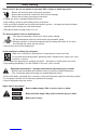
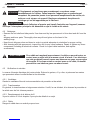
FUMES AND GASES can injure your health.
ARC RAYS can injure eyes and burn. ELECTRIC SHOCK can kill.
• Read and understand the manufacturer’s instructions and your employer’s safety practices.
• Use enough ventilation, exhaust at the arc, or both, to keep fumes and gases away from your
breathing zone and the general area.
• Keep your head out of the fumes.
• Wear correct eye, ear and body protection.
• Do not touch live electrical parts.
• Consult the instruction manual before operating.
For your protection:
• Use hearing protectors.
• Wear a welding helmet.
• Wear appropriate protective clothing, gloves and shoes.
• Wear protective goggles when cleaning welding spatter.
• Use a nonflammable partition/door curtain to protect others from arc rays and sparking.
• Keep all others away during welding.
Fire and Burns - caused by frame heat and arc:
• Keep all flammable materials (wood, cloth, fuel, gases, etc.) away from the welding area.
• Keep the welding area isolated to prevent the spread of fire.
• Ensure that pieces to be welded are clean and the work area is cleared.
• Do not weld on sealed tanks – risk of explosion.
• Keep fire extinguisher nears the welding area.
• Do not use if welder is overloading.
• Watch for risk of fire after welding.Samara Wiebe <[email protected]>, Lindsay Lobb
RESPONSIBILITY
Safety Warning

Electric shock - do not use welder in wet areas. Risk of injury or death may result:
• Ensure unit and work area are properly grounded.
• Ensure that all electrical components are free from damage.
• Ensure that all cables are properly connected.
• Change any worn or damaged cables before use.
• Keep clothing, work area and welding unit dry at all times.
• Keep your body insulated from the work piece and the ground – use approved safety footwear,
especially when working in a moist environment.
• Wear gloves before turning power on or off.
The electromagnetic field can be dangerous:
• If you have a pacemaker, consult your doctor before welding.
The electromagnetic field may interfere with the pacemaker signal.
• Minimize exposure to the electromagnetic field by keeping the cables to one side –
avoid winding the cables around yourself.
• Limit the time spent at the welding site.
Avoid breathing in welding fog and gases:
• Make use of a natural or mechanical air cleaner/aerator in the work area.
• Do not weld the following metals: galvanized steel, stainless steel, copper, zinc, lead,
beryllium or calcium.
• Do not weld near degreasing or spraying operations – phosgene or similar gases may result.
• Stop welding immediately if you feel irritation to the eyes, nose or throat.
Equipment maintenance – improper maintenance may cause injury or death:
• Have the unit assembled and maintained only by licensed, qualified technicians.
• Turn off all power when performing any repair/maintenance work.
• Ensure that cables, grounding wire, connectors, main lead and power supply are working normally.
• Do not tamper with the unit or make any unauthorized changes.
• Keep all equipment safe and secure.
Signs used in the manual:
– Means sudden danger. Risk of serious injury or death.
– Means potential danger. May result in serious injury or death.
Means risk of injury.
DANGER
WARNING
CAUTION
Safety Warning Page 2

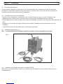
1.1 Product application
MIG welders feature a special tapped transformer adjusting style. It is a lightweight, economical, easy to
operate wire-feed system ideal for use with low-carbon steel and low-alloy steels.
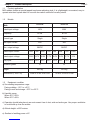
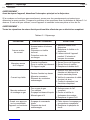
1.2 Models
1.3 Equipment condition
a) Surrounding temperature range
During welding: -10°C to +40°C
During transit and storage: -25°C to +55°C
b) Humidity range
When 40°C <50%
When 20°C <90%
c) Operation should take place in an environment free of dust, acid and active gas. Use proper ventilation
to avoid build up from the welder.
d) Altitude height: ≤1000 metres
e) Gradient of welding power: ≤15°
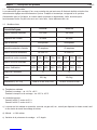
Item 8154700 8154718
Rated input voltage 120V 230V
Frequency 60 Hz 60 Hz
Current type Single Single
Max. input current 20A 20A
Max. output voltage 28VDC 36VDC
Rated output current 25A 35A 50A 75A 30A 50A 75A 105A
Rated output voltage 13.6V 15.7V 16.5V 17.7V 15.5V 16.5V 17.7V 21V
Duty cycle 100% 92% 45% 20% 100% 88% 39% 20%
Insulation grade H H
Weight 23.5 kg 25.6 kg
Dimensions (L x W x H) 50cm x 32 cm x 38.5 cm 72 cm x 32 cm x 54 cm
Chapter 1 – Product description Page 3

1.4 Noise
When the unit is operating, the noise it produces will not exceed 75 decibels.
1.5 Safety
Before operating the unit, read the safety directions to avoid injury caused by improper use.
1.6 Accessories (included)
• One welding hammer/brush
• Welding mask (with black glass)
• Contact tip (replacement part for welding torch)
• Flux-core wire (0.8)
1.7 Parts list - see back page for complete listing.
Chapter 1 Product description Page 4

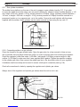
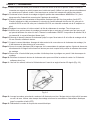
2.1 Ground installation.
If installing the unit to the floor or other fixed surface, ensure that the unit will have proper
ventilation, and will be protected from exposure to dust, dirt, and water. The distance between the back of
the unit and any wall must be a minimum of 46 cm.
2.2 Checking the package contents.
• After receiving the equipment, check for any signs of damage during transport. Notify the dealer
immediately if the unit is damaged or is missing any parts.
• Remove unit from packaging and remove all packing material. Check for loose pieces in box.
• Check all air vents in the unit case. Remove any packaging material blocking vents.
• Assembly of unit should be done where adequate room is available.
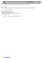
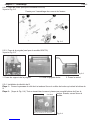
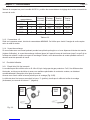
2.3 Installation (refer to fig. 2-1).
Note: 8154700 model does not include kickstand, wheels, axle, handle or brace.
Fig. 2-1
2.3.1 Installing the kickstand (except 8154700).
Position the plastic block into the slot on the front chassis of the unit, and secure using
tapping screws.
Chapter 2 – Assembly Page 5

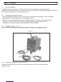
2.3.2 Installing wheels (except 8154700).
See fig. 2-2.
2.3.3 Installing the handle (except 8154700).
See fig. 2-3.
1. Fix handle socket. 2. Fix straight handle. 3. Fix brace.
2.3.4 Fixing the wire reel.
Step 1: Open the right side panel, and remove the wingnut from the wire-feed spool bolt.
Step 2: (See fig. 2-4) Hold the spring and place a new wire spool onto the spool bolt.
Secure with wingnut.
Chapter 2 Assembly Page 6
Wheel and Axle Assembly Drawing
Fig. 2-3
Fig. 2-2
Fig. 2-4
wire spool axle wire spool
right sideboard

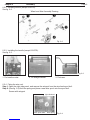
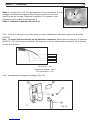
Step 3: (See fig. 2-5) Open the wire-feed impaction component (C).
Thread the wire through the tube. Feed the wire up through the tube
on the welding torch. Close the wire-feed impaction
component (C), and adjust the impaction nut of the wire-feed wheel.
Step 4: Close the right side panel.
Fig. 2-5
2.3.5 Installing the power plug (plug and power cord required for 8154700).
Note: this step must be done by a qualified electrician. Connect a 25A power plug
(8154718: 230 VAC, 25A) to the line cord. Green wire = ground wire.
Ground: Green
Neutral: White
Hot: Black
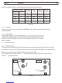
2.3.6 Fixing the face shield (fig. 2-6).
Chapter 2 Assembly Page 7
C
D
Wire-feed mechanism
Black
White
Green
Fig. 2-6

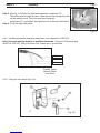
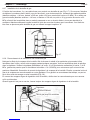
2.3.7 Gas cylinder installation
The welder has a platform on the rear of the unit to support a gas cylinder (see fig. 2-7). If you plan
to move the welder around the shop, use only small cylinders for transport safety (outside diameter = 140
mm, height ≤ 500 mm, weight ≤ 10 Kg, service pressure ≤ 20 Mpa). Larger cylinders (outside diameter >
140 mm, or height > 500 mm, or weight > 10 Kg, service pressure ≤ 20 Mpa) should be secured in a
permanent location or to a separate cart, not to the welder. Secure the small cylinder with the straps
supplied with the welder. Small cylinders can be easily secured in place using the top rack “A”.
2.3.8 Connecting welder to a gas cylinder.
Clean the threads of the gas cylinder valve. Open the gas valve for a few seconds to blow out any
dirt or particles that may have entered the orifice, in order to prevent them from entering the regulator.
Check the regulator (outlet flow meter: 0-25L/Min., inlet gauge: 0-25 Mpa, pressure range for safe
outflow: 0-0.35 Mpa) to make sure that it was supplied with a gasket. Tighten the regulator coupling
to the cylinder gas valve. Now connect the welder gas line to the hose barb outlet on your regulator.
A stainless steel hose clamp can be used to ensure a leak-proof connection (see fig. 2-8).
Check all connections for leaks by opening the regulator and cylinder gas valves.
Always shut off the regulator and cylinder gas valves when the unit is not in use.
Chapter 2 Assembly Page 8
Fig. 2-7
Fig. 2-8
Regulator
Hose barb
Gas line to welder
STRAP
PANEL

Do not operate the unit when the case has been opened; improper cooling can
damage the parts. Make sure all side panels are properly closed.
When welding, always wear a welding helmet, gloves and other guards.
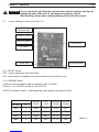
3.1 Layout drawing of control panel (fig. 3-1)
3.1.1 ON/OFF switch.
OFF – means power has been shut down.
ON – means power is supplied to the main transformer and control circuit.
3.1.2 MIN/MAX switch.
Located on the front panel, used in conjunction with 1/2 switch.
See fig. 3-1 for 8154700, and fig. 3-2 for 8154718.
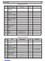
8154700 Comparison table - output adjusting switch position and output current.
Table 3-1
Chapter 3 – Operation Page 9
CAUTION
Overload light
MIN/MAX switch
ON/OFF switch
1/2 switch
Power line
Torch cable
Grounding cable
Switch Position Working
Current
Duty
Cycle
Working
Voltage
No-load
Voltage
MIN/MAX 1/2
MIN 1 25A 100% 13.6V 20V
MIN 2 35A 92% 15.7V 22V
MAX 1 50A 45% 16.5V 25.5V
MAX 2 75A 20% 17.7V 28V
Fig. 3-1

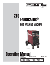
8154718 Comparison table - output adjusting switch position and output current.
Table 3-2
3.1.3 1/2 switch.
Located on the front panel, to the right of the MIN/MAX switch. Select output needed according to
the metal material.
3.1.4 Overload light.
If welding with large current for extended periods, or if you exceed the duty cycle, the
overload lamp will light (yellow) and the machine will stop working until the unit cools.
When the overload lamp lights up you must stop welding and wait about 15 minutes
before continuing.
3.2 Operation process
3.2.1 Using cored wire.
The welder can be used with special 0.8 flux wire that does not require protective gas. This wire, contrary
to electrodes, does not leave slag and gives better bead penetration with substantially lower line absorption.
Make sure you use the proper welding polarity (as shown in fig. 3-2B).
The grounding cable connects with the " + " (positive) terminal, and the welding torch cable connects
with the " – " (negative) terminal.
Fig. 3-2
Chapter 3 Operation Page 10
GAS
AB
Switch Position Working
Current
Duty
Cycle
Working
Voltage
No-load
Voltage
MIN/MAX 1/2
MIN 1 30A 100% 15.5V 21V
MIN 2 50A 88% 16.5V 24.5V
MAX 1 75A 39% 17.7V 29V
MAX 2 105A 20% 21V 36V
NO GAS

Step 1: Use the ground clamp to connect the grounding cable and work piece, or connect to the metal
carriages (as on work table). Make sure the clamp is in full contact with the work piece, and the
surface is free of rust and paint.
Step 2: Select the welding current and adjust the positions of the MIN/MAX and 1/2 switches (use higher
welding current for thicker material).
Step 3: Check the position of the power switch (position must be OFF), then insert the inlet wire to
the socket (8154700 voltage is 120VAC, 8154718 voltage is 230VAC, rated current of
socket ≥ 25A).
Step 4: Discharge the nozzle cover and contact tip at the head of welding torch, pull the
soft pipe.
Step 5: Make sure that the welding tongs that clamp the rod are not in contact with any grounding objects.
Turn the ON/OFF switch to the ON position – the power lamp
will light (green).
Step 6: Press and hold the torch button until the distance between the wire and welding
torch is 30 mm, then release button.
Step 7: Turn off the power. Fix the contact tip and nozzle cover onto the welding torch
(wire must go through the contact tip and nozzle cover).
Step 8: Turn on the power and press the switch a few times. Adjust the speed by
turning the wire feed speed knob, in relation to the position of the welding current selector.
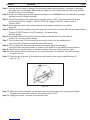
Step 9: Orient yourself on the area to be welded, and place the face shield over your eyes.
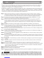
Step 10: Press and hold the torch button as you stroke the area to be welded. The electrode wire
will ignite the arc.
Step 11: Once the arc is ignited, tilt the electrode wire forward at an angle of approximately 35°
(see fig. 3-3).
Fig. 3-3
Step 12: When the weld is complete, lift the electrode wire clearly away from any grounded object.
Set your face shield down and turn the power switch to OFF.
Step 13: Unplug the Power Cord from the electrical outlet.
Chapter 3 Operation Page 11

3.2.2 Using mild steel wire.
• The welder can be used with mild steel wire and shield gas for welding carbon steel. The shielding gas
should be either pure (100%) CO2or a 75% argon - 25% CO2mixture.
• Make sure you use the proper welding polarity (as shown in fig. 3-2A). The grounding cable
connects with the " – " (negative) terminal, and the welding torch cable connects with the " + "
(positive) terminal. The diameter of the wire you select should correspond to the thickness of the work
piece. Make sure that the contact tip you are using is the same size as the wire diameter.
Step 1: Use the ground clamp to connect the grounding cable and work piece, or connect to the metal
carriages (as on work table). Make sure the clamp is in full contact with the work piece, and the
surface is free of rust and paint.
Step 2: Select the welding current and adjust the positions of the MIN/MAX and 1/2 switches (use higher
welding current for thicker material).
Step 3: Check the position of the power switch (position must be OFF), then insert the inlet wire to
the socket (MIG 136 voltage is 120VAC, MIG 156 voltage is 230VAC, rated current of
socket ≥ 20A).
Step 4: Discharge the nozzle cover and contact tip at the head of welding torch, pull the
soft pipe.
Step 5: Make sure that the welding tongs that clamp the rod are not in contact with any grounding objects.
Turn the ON/OFF switch to the ON position – the power lamp
will light (green).
Step 6: Press and hold the torch button until the distance between the wire and welding
torch is 30 mm, then release button.
Step 7: Turn off the power. Fix the contact tip and nozzle cover onto the welding torch
(wire must go through the contact tip and nozzle cover).
Step 8: Open the gas valve on the regulator and set a flow of 5-7 L/Min., depending on the welding
position chosen.
Step 9: Turn on the power and press the switch a few times. Adjust the speed by
turning the wire feed speed knob, in relation to the position of the welding current selector.
Step 10: Orient yourself on the area to be welded, and place the face shield over your eyes.
Step 11: Press and hold the torch button as you stroke the area to be welded. The electrode wire
will ignite the arc.
Step 12: Once the arc is ignited, tilt the electrode wire forward at an angle of approximately 35°
(see fig. 3-3).
Step 13: When the weld is complete, lift the electrode wire clearly away from any grounded object. Set
your face shield down and turn the power switch to OFF.
Step 14: Unplug the Power Cord from the electrical outlet.
Step 15: Close the gas cylinder valve.
Step 16: Depress torch trigger to release gas in regulator (the gas pressure regulator will return to 0).
If welding with large current for extended periods, or if you exceed the duty
cycle, the overload lamp will light (yellow) and the machine will stop working
until the unit cools. When the overload lamp lights up you must stop welding
and wait about 15 minutes before continuing.
Chapter 3 Operation Page 12
CAUTION

4.1 Summary
If the equipment doesn’t work normally, stop using it at once and check for any
signs of trouble. Have the unit inspected by a qualified professional.
Do not allow untrained personnel to check, clean or repair the unit.
Only use replacement parts that have been approved by the manufacturer.
Make sure the main power switch has been disabled, or remove the fuse,
before attempting any type of maintenance on the unit.
4.2 Cleaning
• Remove the unit shell and side panels. Use clean and dry low-pressure air to blow dust and dirt from the
air
alleyway and inner parts. Thoroughly clean any dirt and grime on the head of the
welding tongs.
• Keep the air alleyway clear and clean in order to provide adequate air circulation for proper cooling.
• After cleaning with low-pressure air, inspect the unit for any loose hardware. Repair or tighten any loose
components, including all electrical contacts. Check for frayed cable insulation, and replace
as necessary.
If a cable is improperly replaced, the bare cable may make contact with the
grounding object – the resulting arc can hurt or eyes or cause a fire.
Body contact with cable link or lead may result in severe burns or death.
4.3 Checking and maintenance
Keep the power dry. Remove any grease and make sure the power can’t be damaged by flaming metal and
sparks.
4.3.1 Fan
Keep blower fan clear of dust and grime buildup.
4.3.2 Transformer
The transformer generally needs no maintenance – simply blow off any dust and dirt with
low-pressure air.
4.3.3 Replacing the wire wheel.
See chapter 2.3.4 for replacement instructions.
4.3.4 Cable
Store cable in a clean, dry place.
Chapter 4 - Maintenance Page 13
CAUTION
WARNING
WARNING

5.1 Summary
WARNING:
Before repairing unit, disable the main switch or breaker.
If the welder isn’t working normally, use the following information to pinpoint the possible cause. Compare
the trouble and symptoms with table 5-1 below. If a problem can’t be found, open and inspect all parts and
wires.
WARNING:
All electrical repairs must be done by a qualified electrician.
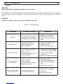
Table 5-1 Troubleshooting
Chapter 5 – Troubleshooting Page 14
PROBLEM POSSIBLE CAUSES REMEDIES
No input
1. No voltage in input terminal.
2. Improper fuse or breaker.
3. Overload protective setting.
1. Check fuse or breaker.
2. Replace fuse or breaker.
3. Let cool for 15 min. and try
again.
Bad wire feed.
1. Not enough pressure.
2. Wing nut is too loose.
3. Wire is oxidated.
1. Tighten the impactor nut.
2. Tighten wing nut.
3. Replace the wire spool.
Current is too low.
1. Input voltage is too low.
2. Bad connection.
3. Conductor elements have
been damaged.
1. Check that the input voltage
is the same as rated voltage.
2. Check grounding cable
connection.
3. Repair by qualified electrician.
Poor gas welding
performance.
1. Little or no gas.
2. Hole is blocked.
3. Hertzian valve is blocked.
4. Bad gas and wire.
1. Check gas supply.
2. Clean with compressed air.
3. Open and check welding
torch.
4. Replace gas and wire.
When pressing switch,
unit does not work.
1. Control valve broke off.
2. Circuit plate damaged.
1. Repair valve by qualified
personnel.
2. Replace circuit plate.

8154718 Welding machine
8154700 Welding machine
No. Name Specification Qty. Remark
1 Welding power MIG 156 1
2 Operating manual 1
3 Weld wire 0.8 (0.9 Kg) 1
4 Straps 2
5 Face shield 1
6 Screening glass 1 With face shield
7 Hammer/brush 1
8 Handle socket 2
9 Kickstand 1
10 Wheel 5" 2
11 Axle socket 2
12 Axle 10 mm 1
13 Straight handle 1
14 Brace 1
15 Contact tip 0.8 1
16 Spanner 1
17 Bolt GB845 ST4.2 x 13 2
18 Bolt GB845 ST4.2 x 20 4
19 Rings GB896 8 2
No. Name Specification Qty. Remark
1 Welding power MIG 136 1
2 Operating manual 1
3 Weld wire 0.8 (0.9 Kg) 1
4 Gallus (straps) 2
5 Face shield 1
6 Screening glass 1 With face shield
7 Hammer/brush 1
8 Handle socket 2
9 Straight handle 1
10 Contact tip 0.8 1
11 Spanner 1
12 Bolt GB845 ST4.2 x 20 4
Parts List Page 15

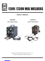
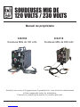
SOUDEUSES MIG DE
120 VOLTS / 230 VOLTS
8154718
8154700
Soudeuse MIG de 120 volts Soudeuse MIG de 230 volts
Manuel du propriétaire
Avant de vous servir de l’appareil pour la première fois, vous devez lire attentivement
et bien comprendre toutes les instructions.
Conservez ce manuel pour pouvoir le consulter plus tard.

C’est à l’utilisateur qu’incombe la responsabilité de bien inspecter l’équipement avant de l’utiliser. S’il y manque une
ou des pièces ou bien si l’appareil a été endommagé, ne vous en servez pas. Le fabricant stipule que les pièces de
rechange doivent être commandées à un distributeur autorisé.
Avant de changer quelque pièce que ce soit, l’utilisateur doit obtenir la permission du fabricant. Si l’utilisateur ne se
conforme pas à cette exigence, il risque de provoquer un accident dont il serait entièrement responsable à cause
d’un emploi inapproprié de l’appareil.
Table des matières
Chapitre Contenu Pages
Sécurité Mises en garde 2
Chapitre 1 Description des produits 3
Chapitre 2 Assemblage 5
Chapitre 3 Fonctionnement 9
Chapitre 4 Entretien 13
Chapitre 5 Dépannage 14
Les ÉMANATIONS et les GAZ provenant d’une soudeuse peuvent nuire à votre santé. Les RAYONS de l’ARC
peuvent causer des lésions aux yeux et des brûlures. Un CHOC ÉLECTRIQUE peut provoquer la mort.
• Vous devez lire et bien comprendre toutes les instructions fournies par le fabricant, ainsi que les règles de sécurité
stipulées par votre employeur.
• Prévoyez suffisamment de ventilation ou un moyen d’évacuation efficace à proximité de l’arc, ou bien les deux,
pour garder les émanations et les gaz à une distance prudente de votre poste de travail et du lieu de travail en
général.
• Ne respirez jamais les gaz et les émanations du travail de soudage.
• Portez une protection appropriée pour vos yeux, vos oreilles et votre corps.
• Ne touchez jamais à des pièces électriques sous tension.
• Avant de vous servir de l’appareil, consultez toujours le manuel fourni.
Pour votre protection :
• Utilisez des protecteurs antibruit pour vos oreilles.
• Portez un casque de soudeur.
• Portez des vêtements de protection, ainsi que des chaussures et des gants appropriés.
• Portez des lunettes de protection lorsque vous enlevez les éclaboussures de soudage.
• Utilisez une cloison ou un rideau de porte ininflammable pour protéger les autres personnes contre les rayons de
l’arc et les étincelles.
• Durant le travail de soudage, demandez à tout le monde de se tenir à une distance prudente.
Incendie et brûlures que l’arc et la chaleur du châssis pourraient causer :
• Gardez toutes les matières inflammables (bois, tissus, carburants, gaz, etc.) à l’écart de l’aire de
soudage.
• L’aire de soudage doit être isolée pour prévenir, le cas échéant, la propagation du feu.
• Les pièces à souder doivent être propres et le lieu de travail ne doit pas être encombré.
• N’effectuez jamais des travaux de soudage sur des réservoirs scellés, car ils présentent un danger d’explosion.
• Gardez toujours un extincteur chimique à portée de la main.
• Ne vous servez pas de la soudeuse en cas de surcharge.
• Même après que la soudure est achevée, n’oubliez pas qu’il existe encore des risques d’incendie.
Responsabilité
Avertissement de sécurité

Si la soudeuse est employée dans un endroit humide, il existe alors un danger de choc électrique
qui pourrait entraîner des blessures ou même la mort :
• L’appareil et le poste de travail doivent être correctement mis à la terre.
• Assurez-vous que tous les composants électriques sont intacts et en bon état.
• Tous les câbles doivent être correctement connectés.
• S’il y a des fils trop usés ou endommagés, il faut les remplacer avant de se servir de l’appareil de soudage.
• Les vêtements, la zone de travail et l’appareil de soudage doivent toujours être secs.
• Gardez votre corps isolé de la pièce à souder et de la prise de terre. Portez des chaussures de sécurité
approuvées, surtout quand vous travaillez dans un endroit humide.
• Portez des gants pour mettre l’appareil en marche et pour le débrancher.
Le champ électromagnétique peut s’avérer dangereux :
• Si vous avez un stimulateur cardiaque (pacemaker), consultez votre médecin avant d’effectuer des
travaux de soudage. En effet, le champ magnétique pourrait entraver le signal du stimulateur cardiaque.
• Minimisez l’exposition au champ magnétique en gardant les câbles sur un même côté. Évitez d’enrouler ces câbles
autour de votre personne.
• Limitez le temps que vous passez à proximité de l’équipement de soudage en marche.
Évitez de respirer les fumées et les gaz produits par le soudage :
• Utilisez un aérateur ou épurateur d’air naturel ou mécanique dans l’endroit où vous travaillez.
• Évitez de souder les métaux suivants : acier galvanisé, acier inoxydable, cuivre, zinc, plomb, béryllium
et calcium.
• Ne soudez jamais à proximité d’opérations de dégraissage ou de pulvérisation, car le soudage pourrait alors
produire du phosgène ou un autre gaz semblable.
• Si vous ressentez une irritation des yeux, du nez ou de la gorge, cessez immédiatement de souder.
Un mauvais entretien de l’équipement pourrait causer des blessures ou même la mort d’une
personne :
• L’appareil doit toujours être assemblé puis entretenu par des techniciens compétents et autorisés.
• Coupez le courant électrique avant de procéder à des travaux de réparation ou d’entretien
• Assurez-vous que les câbles, le fil de terre, les connecteurs, le conducteur principal et l’alimentation électrique sont
en bon état et fonctionnent normalement.
• Vous ne devez jamais modifier l’appareil sans avoir obtenu, au préalable, l’autorisation du fabricant.
• Il faut garder l’équipement en bon état pour qu’il soit sécuritaire.
Signs used in the manual:
– Danger immédiat qui pourrait entraîner des blessures graves ou même la mort.
– Danger potentiel qui pourrait entraîner des blessures graves ou même la
mort.
Risque de blessure.
DANGER
AVERTISSEMENT
ATTENTION
Avertissement de sécurité Page 2

1.1 Utilisation des produits
La soudeuse MIG (pour soudage à l’arc sous protection de gaz inerte avec fil-électrode fusible) est dotée d’un
mécanisme de réglage avec transformateur à prises. Pratique et économique, cet appareil a un système
d’alimentation pour le fil d’apport, un volume réduit qui permet un déplacement facile, de même qu’un
fonctionnement facile. On peut s’en servir sur l’acier doux, l’acier faiblement allié, etc.
1.2 Modèles offerts
a) Température ambiante
Pendant le soudage : de -10°C à +40°C
Pendant le transport et le remisage : de -25°C à +55°C
b) Humidité opposée
Quand il fait 40°C, moins de 50 %
Quand il fait 20°C, moins de 90 %
c) La teneur de l’air ambiant en poussière, en acide, en gaz actif, etc., ne doit pas dépasser le niveau normal, sauf
si elle résulte du travail de soudage lui-même.
d) Altitude : ≤ 1000 mètres
e) Variation de la puissance de soudage : ≤ 15 degrés
Caractéristiques 8154700 8154718
Tension d’entrée nominale 120 volts 230 volts
Fréquence du courant 60 hertz 60 hertz
Type de courant monophasé monophasé
Intensité maximale à l’entrée 20 ampères 20 ampères
Tension de sortie maximale 28 volts CC 36 volts CC
Intensité de sortie nominale 25A 35A 50A 75A 30A 50A 75A 105A
Tension de sortie nominale 13,6V 15,7V 16,5V 17,7V 15,5V 16,5V 17,7V 21V
Facteur d’utilisation 100% 92% 45% 20% 100% 88% 39% 20%
Qualité de l’isolement H H
Poids 23,5 kg 25,6 kg
Dimensions (L x L x H) 50cm x 32 cm x 38,5 cm 72 cm x 32 cm x 54 cm
Chapitre 1 — Description des produits Page 3
La page est en cours de chargement...
La page est en cours de chargement...
La page est en cours de chargement...
La page est en cours de chargement...
La page est en cours de chargement...
La page est en cours de chargement...
La page est en cours de chargement...
La page est en cours de chargement...
La page est en cours de chargement...
La page est en cours de chargement...
La page est en cours de chargement...
La page est en cours de chargement...
-
 1
1
-
 2
2
-
 3
3
-
 4
4
-
 5
5
-
 6
6
-
 7
7
-
 8
8
-
 9
9
-
 10
10
-
 11
11
-
 12
12
-
 13
13
-
 14
14
-
 15
15
-
 16
16
-
 17
17
-
 18
18
-
 19
19
-
 20
20
-
 21
21
-
 22
22
-
 23
23
-
 24
24
-
 25
25
-
 26
26
-
 27
27
-
 28
28
-
 29
29
-
 30
30
-
 31
31
-
 32
32


Power Fist 8154700 Le manuel du propriétaire
- Catégorie
- Système de soudage
- Taper
- Le manuel du propriétaire
dans d''autres langues
- English: Power Fist 8154700 Owner's manual
Autres documents
-
MasterCraft MIG 180 Manuel utilisateur
-
 Thermal Arc 210 FABRICATOR® Mig Welding Machine Manuel utilisateur
-
ESAB 210 FABRICATOR® Mig Welding Machine Manuel utilisateur
-
Lincoln Electric Red-D-Arc GX-271 Mode d'emploi
-
 Thermal Arc 210 FABRICATOR® Mig Welding Machine Manuel utilisateur
-
-
-
-
-

