MasterCraft MIG 180 Manuel utilisateur
- Catégorie
- Système de soudage
- Taper
- Manuel utilisateur

058-9306-4
MIG 180 INVERTER WELDER
INSTRUCTION MANUAL

Quick Start Guide
If any parts are
missing or damaged,
or if you have any
questions, please call
1-800-689-9928.
Read and understand this instruction manual
thoroughly before using the product. It contains
important information for your safety, as well as
operating and maintenance advice.
Keep this instruction manual for future use. Should
this product be passed on to a third party, this
instruction manual must be included.
MIG 180 INVERTER WELDER 058-9306-4

QUICK START GUIDE
MIG 180 INVERTER WELDER 058-9306-4
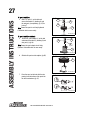
MIG welding
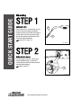
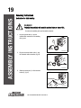
STEP 1
Installing the wire
Remove the nozzle (1) and contact tip (2) from
the end of the torch assembly. Identify the
leading end of the wire secured on the edge of
the wire spool. Place the spool onto the hub
with the wire passing from the bottom of the
spool into the drive mechanism.
pages 26-27, steps 1-12
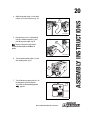
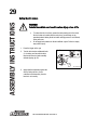
STEP 2
Setting the wire tension
Press the trigger on the gun. Turn the drive
tension adjustment knob (1) clockwise to
increase the drive tension until the wire feeds
smoothly without slipping.
page 29, steps 1-3
1
2
MC-589306-34
WARNING / AVERTISSEMENT
ELECTRIC SHOCK can kill
UN CHOC ÉLECTRIQUE peut tuer.
MOUING PARTS can cause injury.
LES PIÉCES MOBILES peuvent causer des blessures.
•
We
lding
w
ire
a
n
d drive part
s
m
a
y
be
at
w
elding v
ol
tage.
•
Keep away
from
m
ov
ing p
a
rts.
• Ne
v
ous
approchez pas
de
s pièce
s
mo
bile
s
.
•
M
ain
t
ene
z
tous les
c
ouv
e
r
cles,
pan
ne
au
s et
port
es
f
ermés et
s
ol
ide
m
e
n
t
e
n
pla
ce
.
• Keep
a
ll
doors,
c
ov
ers a
n
d
panels
closed and
s
e
c
urely
in pla
c
e.
• Le
f
il
de
so
u
dure
e
t
les
pièces
motrices son
t
peut-être a la
t
ens
ion
de
s
ou
d
a
ge.
•
Ne tou
ch
e
z
p
a
s
le
fil oules
pa
r
ties motric
es
à
m
ain
s
n
ues
ou
av
e
c
de
s
outils lorsque la
de
tente es
t
s
ous, pre
ssion.
• Do no
t
to
uch
w
ire
or
driv
e
p
arts
with b
a
re ha
nds
or
too
l
s
w
hen
trigge
r
is
de
p
re
s
s
e
d.
MIG
SPOOL GUN/PISTOLET À BOBINE
When normal MIG welding,
this switch should be turned in “MIG” position.
when using spool gun.
this switch should be in “Spool gun” position.
Ce commutateur doit être placé à la position « MIG »
si vous effectuez du soudage MIG normal
et à la position « SPOOL GUN »
si vous utilisez un pistolet à bobine.
DCEN
DCEN
FLUX CORE WIRE
FIL AVEC ÂME EN FLUX
C
o
urant continu pol
arité normale
Polarity
s
witch s
et
ti
n
g
:
Régla
g
e du
c
ommuta
te
ur de
pol
a
r
it
é:
Direct
cur
rent
,
e
lectrod
e
n
agative
DCEP
DCEP
MIG
MIG
Direct cur
ren
t, e
l
ectro
de
po
si
ti
v
e
C
ou
r
ant continu, e
l
ectrode positive
Po
l
a
ri
ty
switch
s
etti
n
g
:
Régl
age du co
m
mu
ta
teu
r de po
l
ar
i
té:
ST
ICK
BAGUETTE
Polar
ity
s
wit
c
h
s
e
t
tin
g
:
Réglage
du commu
t
a
t
e
u
r
de p
ola
rit
é
:
+
+
+
-
-
-
NO GAS/PAS DE GAZ
GAS/GAZ
AVERTISSEMENT
SHOCK can kill
C ÉLECTRIQUE peut tuer.
PARTS can cause injury.
MOBILES peuvent causer des blessures.
e and drive parts may be at welding voltage.
from moving parts.
chez pas des pièces mobiles.
les couvercles, panneaus et portes fermés et
solidement en place.
rs, covers and panels closed and securely in place.
udure et les pièces motrices sont peut-être a la
tension de soudage.
pas le fil oules parties motrices à mains nues ou
avec des outils lorsque la detente est sous, pression.
ch wire or drive parts with bare hands or tools when
trigger is depressed.
DCEN
DCEN
FLUX CORE WIRE
FIL AVEC ÂME EN FLUX
Courant continu polarité normale
Polarity switch setting:
Réglage du commutateur de polarité:
Direct current, electrode nagative
DCEP
DCEP
MIG
MIG
Direct current, electrode
Courant continu, electrode
Polarity switch setting:
Réglage du commutateur de polar
+
+
-
-
NO GAS/PAS DE GAZ
GAS/
1
MC-589306-39

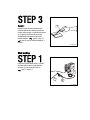
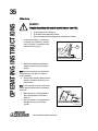
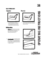
STEP 3
Operation
Hold the torch in one hand and turn the wire
speed dial with the other hand to its maximum
position. Pull the trigger (1) on the torch to start an
arc. Drag the torch on the work piece while
simultaneously turning the wire speed dial
counterclockwise. page 31, steps 4-5
page 32 (refer to welding techniques, if
needed)
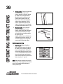
Stick welding
STEP 1
Plug in the electrode holder cable (1) into the
electrode cable connection and attach the
electrode (2) in the electrode holder (3)
page 19, steps 2-3
1
MC-589306-42
MC-589306-12
9
9
3
4
5
6
7
8
WI
RE
STICK
A
10
3
4
5
6
7
8
10
POWER
WA
RNING
W
ORK
V
A
ST
ICK
MIG
GA
S IN
ERTE
M
IG
V
GAS INERTE
ARC
ARC
F
IL
MAR
CH
E
058-9306-4
AVERTISSEMENT
INTENSITÉ
MIG 180 INVERTER WELDER
SOUDEUSE À ONDULEUR MIG 180
2
1
3

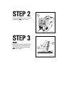
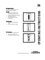
STEP 2
Turn the mode selector switch (1) to the stick
welding mode. page 20, step 6
STEP 3
Operation
Strike an arc by scratching the work piece (1)
with the electrode (2) and raising it by 1/8"
and maintain the gap throughout the weld.
page 35, steps 1-5
MC-589306-15
9
9
3
4
5
6
7
8
WIRE
STICK
A
10
3
4
5
6
7
8
10
POWER
WARNING
WORK
V
A
STICK
MIG
GAS INERTE
MIG
V
GAS INERTE
ARC
A
R
C
F
IL
MARCHE
058-9306-4
AVERTISSEMENT
INTENSITÉ
MIG 180 INVERTER WELDER
SOUDEUSE À ONDULEUR MIG 180
1
MC-589306-47
1/8"
2
1

TABLE OF CONTENTS
2
MIG 180 INVERTER WELDER 058-9306-4
QUICK START GUIDE
TECHNICAL SPECIFICATIONS 3
SAFETY GUIDELINES 4–8
KEY PARTS DIAGRAM 9–11
IMPORTANT INFORMATION 12–18
ASSEMBLY INSTRUCTIONS 19–29
OPERATING INSTRUCTIONS 30–41
MAINTENANCE 42
TROUBLESHOOTING 43–44
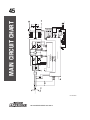
MAIN CIRCUIT CHART 45
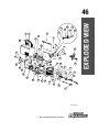
EXPLODED VIEW 46
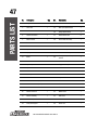
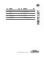
PARTS LIST 47–48
WARRANTY 49–50

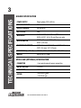
TECHNICAL SPECIFICATIONS
3
MIG 180 INVERTER WELDER 058-9306-4
WELDER SPECIFICATION
SPOOL GUN (OPTIONAL) SPECIFICATION
POWER SUPPLY Single-phase, 230 V, 60 Hz
NO-LOAD VOLTAGE 78 V
OUTPUT CURRENT 30–200 A DC
DUTY CYCLE 30%
WIRE USED
0.023–0.035"
(0.6
–
0.9 mm)
MIG wire
0.030–0.035"
(0.8
–
0.9 mm)
flux-core wire
WIRE DIAMETER
0.023"
(0.6 mm)
, 0.030"
(0.8 mm)
,
0.035"
(0.9 mm)
ELECTRODE DIAMETER 1/16"
(1.6 mm)
, 5/64"
(2.0 mm)
, 5/32" (4.0 mm),
3/32"
(2.5 mm)
, 1/8"
(3.2 mm)
DIMENSIONS (L x W x H) 17 7/10 x 9 2/5 x 13 4/5"
(450 x 239 x 351 mm)
WEIGHT 48 lb 2 oz
(21.8 kg)
CONNECTOR 4-pin quick connect power connection
MOTOR VOLTAGE 24 V DC
WIRE SPEED 590"/min
RATING
200 A w/CO
2
gas
140 A A/Ar gas

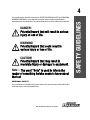
SAFETY GUIDELINES
4
MIG 180 INVERTER WELDER 058-9306-4
This manual contains information that relates to PROTECTING PERSONAL SAFETY and PREVENTING
EQUIPMENT PROBLEMS. It is very important to read this manual carefully and understand it
thoroughly before using the product. The symbols listed below are used to indicate this information.
Note – The word “Note” is used to inform the
reader of something he/she needs to know about
the tool.
PERSONAL SAFETY
These precautions are intended for the personal safety of the user and others working with the user.
Please take time to read and understand them.
DANGER!
Potential hazard that will result in serious
injury or loss of life.
WARNING!
Potential hazard that could result in
serious injury or loss of life.
CAUTION!
Potential hazard that may result in
moderate injury or damage to equipment.

SAFETY GUIDELINES
5
MIG 180 INVERTER WELDER 058-9306-4
DANGER!
Potential hazard that will result in serious injury or loss of life.
• Keep children or other personnel away from the work area while welding. Do
not allow children or persons with mental or physical disabilities to handle
the welder.
• Do not use the welder in the presence of flammable liquids or gases. Sparks
that are created during use may ignite gases.
• Always ensure that a fire extinguisher is available in an adequate distance
within the welding environment.
• Have the welder repaired by a qualified technician in accordance with local,
provincial and national codes.
• Do not repair or maintain the welder while the power is on.
• Do not use an ungrounded power source, as it might cause electrical shock
to the user.
• The welding process must conform to ANSI Z49.1; NFPA 51; OSHA 29 CFR,
part 1910, sub part Q; CSA W117.2; American Welding Society standard A6.0.
• Do not expose the welder to rain.
• Always disconnect the power supply when working on internal components.
• Do not touch the PC board without being properly grounded with a wrist
strap. Place the PC board in a static proof bag while shipping.
• Make sure harmful arc rays are shielded from view of other personnel.
• Do not operate the welder in humid, wet or poorly ventilated areas.
• Risk of electric shock: Do not touch electrical live parts or metal
components connected to the welding wire, as doing so may cause fatal
shock and severe burns. Secure the ground lead before welding. Poor ground
connection creates hazardous situation. Wear a dry protective apparel like a
coat, shirt, gloves, and insulated footwear.

SAFETY GUIDELINES
6
MIG 180 INVERTER WELDER 058-9306-4
• Risk of explosion: Keep high pressure shielding gas cylinder away from
welding or electrical circuits. Never expose cylinders to high heat, sparks,
open flames, mechanical shocks or arcs. Do not touch the cylinder with MIG
gun and do not weld on the cylinder. Use proper regulators, gas hoses and
fittings for the specific application. Use protective cylinder cap whenever
possible.
• Risk for breathing: Never directly inhale the emission of harmful fumes
during welding. Make sure the work area is clean, dry and ventilated. Use a
ventilation device to remove welding fumes from the work environment.
• Do not weld on coated materials like galvanized, cadmium plated or
contacting zinc, mercury or barium, as they emit harmful fumes that are
dangerous to breathe. If required, use a respirator with air supply or remove
coating from the material in the weld area.
• Do not weld near materials that will emit toxic fumes when heated. Vapours
from cleaners, sprays and degreasers can be highly toxic when heated.
• Risk of burns: Do not touch the welded materials with bare hands, as the
welded materials are hot and can cause severe burns. Do not touch MIG gun
nozzle or tip of the electrode holder after welding until it has been cooled.
• Wear garments that are oil-free with no pockets or cuffs that will collect
sparks.
• Risk of fire: Do not weld on containers or pipes that contain flammable,
gaseous or liquid combustibles. Welding creates sparks and heat that ignite
flammable and explosive materials. Remove all flammable materials within
35 feet of the welding arc or tightly cover the flammable materials with
fireproof covers. Ensure that flying sparks do not cause fires or explosions in
hidden areas, cracks or areas that are out of vision. Use a fire extinguisher in
the work area. Do not have any items that are combustible, such as lighters
or matches
• Connect the work lead to the weld area as close as possible to prevent any
unknown, unintended paths of electrical current from causing electrical
shock and fire hazards. To prevent any unintended arcs after welding, cut off
the excess wire that extends past the end of the nozzle more than ¼".

SAFETY GUIDELINES
7
MIG 180 INVERTER WELDER 058-9306-4
• Risk of UV and IR arc rays: Do not look at the welding arc without proper eye
protection, as the welding arc produces ultraviolet (UV) and infrared (IR) rays.
Use shields that adheres to ANSI Z87.1. For welders under 160 A output, use a
shade 10 lens; for above 160 A, use a shade 12 lens. Wear flame retardant
clothes, leather shirts, pants or shoes to cover the bare skin from the arc.
• Use appropriate shield to prevent other personnel from being affected by
harmful rays.
• Risk of electromagnetic fields: Electromagnetic field can damage electrical
and electronic devices like pacemakers and hearing aids. Make sure people
using pacemakers are away from your welding area when welding. Always
wrap the MIG gun and ground cable together.
WARNING!
Potential hazard that could result in serious injury or loss of life.
•
Do not allow unskilled or untrained individuals to install and operate this
welder.
• Keep hands and fingers away from moving parts such as drive roll or fan
while the welder is in use.
• Before operating the welder, check the insulation of the ground cable, power
cord, and welding cable for damage. Replace or repair the damaged
components before using the welder. Use only recommended parts for
replacement.
• Avoid contacting or touching welding wire, work piece, ground connection or
electrode from another welder.
• Do not drape cables over or around the body.
• Do not point the MIG gun toward yourself or other personnel.
• Consult a doctor before using the electric arc welder.
• Always have a secure stance while welding to prevent accident.
• Do not use this welder when you are tired or under influence of alcohol or
drugs.
• Connect the ground lead close to the work area to ensure proper ground
connection.
• Always secure the high pressure cylinder upright to a cart or stationary
object.
• Do not use a welder to thaw frozen pipes.
• Do not look into the valve of the high pressure cylinder when opening it.

SAFETY GUIDELINES
8
MIG 180 INVERTER WELDER 058-9306-4
Note: Recycle unwanted materials rather than disposing of as waste. Sort the tools, hoses, and
packaging in specific categories. Take them to the local recycling centre or dispose of in an
environmentally safe way.
CAUTION!
Potential hazard that may result in moderate injury or damage to
equipment.
• Do not operate the welder if the welding cables, electrode, MIG gun, wire or
wire feed system is wet. Do not immerse them in water. The welder and its
components must be completely dry before attempting to use the welder.
• Keep the welder in the OFF position when not in use.
• Do not wear watches, rings, bracelets, or loose clothing when using the
welder.
• Maintain a correct position while using the welder. Mount the welder on a
secure bench or cart to prevent it from tipping over or falling.
• Wear a full covered helmet with appropriate shade that conforms to
ANSI Z87.1 safety standard, proper gloves, and protective clothing such as
leather shirt, coat, pants, and insulated footwear to prevent the skin from
being exposed to hot metals, UV and IR rays while welding.
• Do not overheat or overuse the welder to prevent it from being heated. Allow
proper cooling time between duty cycles. Always use this welder in the rated
duty cycle to prevent excessive heat and failure.
• Ensure that all the components are clean and in good working condition before
use.
• Do not use an extension cord, as it causes the voltage to drop and affects
the performance of the welder. If needed, use an extension cord having a
minimum size of 12 gauge and maximum length of 25 feet.
• Use safety goggles and ear protection:
Wear safety glasses with side shields when operating the
welder and verify that others in the work area are also
wearing safety glasses. Safety glasses must conform to
American National Standards Institute (ANSI Z87.1)
requirements and must provide protection from flying
particles from the front and the sides.
Always wear ear protection to help prevent hearing damage.
Failure to comply may result in loss of hearing.
MC-OM-01

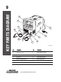
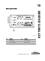
KEY PARTS DIAGRAM
9
MIG 180 INVERTER WELDER 058-9306-4
No. Description No. Description
1
Voltage control (MIG mode) / Amperage
control (stick mode)
7 MIG gun trigger connection
2 Wire feed speed control 8 MIG gun cable
3 Power cord 9 Ground cable with clamp
4 Wire drive compartment door 10 MIG gun trigger cable
5 MIG gun connection 11 Ground cable connection
6 Electrode cable connection
MC-589306-01
GAS INER
9
9
3
4
5
6
7
8
WIRE
MIG
V
STICK
A
10
3
4
5
6
7
8
10
POWER
WARNING
WORK
V
A
STICK
MIG
2
5
4
3
6
7
8
9
10
11
FIL
AVERTISSEMENT
1
GAS INERTE
ARC
ARC
MARCHE
058-9306-4
INTENSITÉ
MIG 180 INVERTER WELDER
SOUDEUSE À ONDULEUR MIG 180

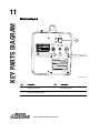
KEY PARTS DIAGRAM
10
MIG 180 INVERTER WELDER 058-9306-4
Welder upper front panel
No. Description No. Description
1 Power ON indicator 3 Output current indicator
2 Thermal overload indicator 4 Mode selector switch
WIRE
STICK
MIG
GAS INERTE
GAS INERTE
V
A
POWER
WARNING
WORK
V
A
STICK
MIG
1
2
3
4
5
6
7
8
9
10
1
2
3
4
5
6
7
8
9
10
1
2
3
4
MC-589306-02
FIL
ARC
ARC
AVERTISSEMENT
058-9306-4
INTENSITÉ
MARCHE

KEY PARTS DIAGRAM
11
MIG 180 INVERTER WELDER 058-9306-4
Welder back panel
No. Description No. Description
1 Primary power switch 3 Inert gas connection
2 Current overload circuit breaker
GAS INPUT
ENTRÊE DE GAZ
NORMAL
NORMAL
220V ~ 240V
1PH
OFF
ON
MARCHE
ARRÊT
POWER
PUISSANCE
OVER CURRENT
SURINTENSITEE
1
2
3
MC-589306-03
ELECTRICAL WARNING
AVERTISSEMENT RELATIE À L’ÉLECTRICITÉ
• Disconnect from power supply before servicing.
• Do not operate with any panels or covers removed.
• Débranchez le cordon de la source d’alimentation avant l’entretien.
• Ne faites pas fonctionner cet appareil avec les panneaux ou les couvercles retirés.
• L’entretien de cet appareil doit toujours être effectué par un technicien Qualifie.
• Service on this machine should only be performed by
a Qualified technician.
MIG
GAZ INERTE
STICK
ARC
0589306
OCV 78Vdc
OCV 78Vdc
160 A
22 V
140 A
25.6 V
230 V AC, 30 A max

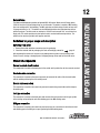
IMPORTANT INFORMATION
12
MIG 180 INVERTER WELDER 058-9306-4
General use
The Mastercraft
Maximum
®
portable and gasless MIG 180 Inverter Welder uses AC single phase
230V, 60 Hz with a 30 A time delayed fuse or circuit breaker. The welder is capable of MIG welding,
flux-core welding and DC stick welding. The MIG mode has an infinite voltage control and can weld
24 gauge mild steel to 1/4". The welder can also MIG weld stainless steel and aluminium with an
optional spool gun. The stick mode can weld up to
180
A DC and can weld 3/16" on mild steel in a
single pass. The welder provides wire feed speed control, overload and thermal protection. The
welder can be used as a portable multi-purpose machine.
Guidelines for proper usage and description
Removing from carton
1. Remove the welder and other accessories from the packaging.
2. Check the contents with the packaging list. Refer to Packaging content list page 18.
After unpacking the welder unit, inspect for any damage that may have occurred during transit.
Check for loose, missing or damaged parts. A shipping damage claim must be filled with carrier.
Welder kit components
Current overload circuit breaker
This component is located on the back panel of the welder and it protects the unit from current overload.
Electrode cable connection
This connection is located on the lower front panel and connects the cable of the electrode holder
with the welding unit during the stick welding mode.
Ground cable connection
This connection is located in the lower front panel and connects the ground cable and the clamp to
the welding unit.
Inert gas connection
This connection is located on the back panel and connects the inert gas hose from the gas cylinder
to the welding unit providing the unit with shielding gas in the MIG welding mode.
MIG gun connection
This connection is located in the lower front panel and serves as a connection for both the wire feed
and shielding gas for the MIG gun or spool gun during the MIG welding mode.

IMPORTANT INFORMATION
13
MIG 180 INVERTER WELDER 058-9306-4
MIG gun trigger connection
This MIG gun trigger connection (1) is located
in the lower front panel and connects the 4-pin
quick connect plug of the MIG gun or the spool
gun (not included) with the welding unit.
Connections 1 and 2 are provided for the MIG
gun/spool gun and connections 3 and 4 are
provided for the wire feed motor.
Mode selector switch
This switch is located on the upper front panel of the welder and is used to select either MIG
welding mode or stick welding mode.
Power ON indicator
This indicator is located on the upper front panel of the welder and glows when the primary power
plug is connected to the power supply and the switch is turned ON.
Primary power switch
This switch is located on the back panel of the welder and enables to turn the welding unit ON or OFF.
Spool gun selector
The spool gun selector (1) is located inside the
wire compartment. This selector is switched to
spool gun mode when an optional spool gun
(not included) is being used, otherwise it stays
in the MIG mode. Refer to spool gun’s manual
for its connection instructions.
Thermal overload indicator
This indicator is located on the upper front panel of the welder and glows when the thermal overload
circuit is activated. The welding unit stops working during this period protecting the unit from any
damage. The cooling fan of the welding unit continues to work even if the welding unit is shut down
by the thermal overload circuit.
12
3
4
MC-589306-35
1
MIG 180 INVERTER WELDER
SOUDEUSE À ONDULEUR MIG 180
WARN
IN
G /
AV
ER
TI
S
SEM
E
N
T
E
L
ECTRIC
SHOCK
c
a
n
k
ill
U
N C
H
O
C
É
L
EC
TR
IQUE
p
e
ut t
u
er.
MOUING PAR
TS
c
a
n
ca
u
se i
n
j
u
ry.
LE
S
P
IÉC
E
S
MO
BILE
S
p
euvent c
a
us
e
r d
e
s
b
l
e
ss
ur
es.
•
W
e
l
di
ng wi
r
e an
d
dri
v
e part
s
m
ay
be
at
w
el
d
i
n
g
v
o
l
t
ag
e.
•
Keep
aw
a
y fro
m
m
o
v
i
ng p
ar
t
s
.
•
Ne
v
o
u
s
appr
oc
he
z
p
as
d
es
piè
ces
m
ob
i
l
e
s
.
•
M
ai
n
t
en
ez
t
o
us
l
es
co
uv
ercl
es,
p
an
neau
s
e
t p
orte
s
f
erm
és
et
s
o
l
i
dem
e
n
t
e
n
p
lac
e
.
•
Keep
al
l
do
o
rs,
c
overs
a
n
d p
an
el
s
cl
o
s
ed
a
n
d
s
ecu
r
el
y
i
n pl
ac
e
.
• Le
fi
l
d
e s
o
udu
r
e et
l
e
s
pi
èces
m
o
t
r
i
ces
s
o
n
t
peu
t
-ê
t
re
a l
a
tens
i
o
n de s
o
udag
e.
• N
e tou
ch
ez p
a
s
l
e fil
o
ules
parti
es
mo
t
r
i
c
e
s à m
a
in
s
n
ues
o
u
av
ec de
s
o
u
til
s
l
o
rs
que l
a det
en
t
e es
t s
o
u
s
,
p
r
es
s
i
o
n.
•
D
o
not
to
uch
wi
r
e
or drive parts
wi
t
h
b
ar
e h
a
n
d
s
or
to
o
l
s
w
hen
t
r
i
g
g
e
r
i
s
depr
e
ss
ed.
MIG
SPOOL GUN/PISTOLET À BOBINE
When normal MIG welding,
this switch should be turned in “MIG” positio
n.
when using spool gun
.
this switch should be in “
Spool gun” position.
Ce commutateur doit être placé à la position «
MIG »
si vous effectuez du soudage MIG normal
et à la p
osit
ion « SPOOL GUN »
si vous utilisez un pistolet à bobine
.
D
CEN
D
CE
N
FL
UX
COR
E
WIRE
FIL AVE
C ÂME
EN
FL
U
X
C
ou
r
a
nt
con
t
inu
po
la
ri
t
é no
r
ma
le
P
ol
a
rit
y
sw
it
c
h
se
t
tin
g
:
R
é
g
la
ge
du
c
o
mmut
a
t
e
u
r de polarit
é
:
D
i
r
e
ct
c
urrent
, e
lec
t
ro
d
e
nagat
i
ve
DC
E
P
DC
EP
M
IG
M
IG
D
i
rect cu
rren
t
,
el
ectro
de po
s
i
ti
ve
C
o
ur
an
t co
nt
in
u
, el
ectro
d
e
p
o
s
i
ti
v
e
P
o
l
ari
t
y
s
w
i
t
c
h
s
etti
n
g
:
Rég
l
a
g
e du
co
m
mu
tateu
r d
e
p
ola
ri
té
:
S
T
ICK
BAGUETTE
P
o
l
ari
t
y
sw
i
tch
se
ttin
g
:
R
é
glag
e
d
u c
om
mu
ta
t
e
u
r
d
e
p
o
larité
:
+
+
+
-
-
-
NO
GAS/P
A
S DE G
A
Z
G
A
S
/GA
Z
MIG
SPOOL GUN/PISTOLET À BOBINE
When normal MIG welding,
this switch should be turned in “MIG” position.
when using spool gun.
this switch should be in “Spool gun” position.
Ce commutateur doit être placé à la position « MIG »
si vous effectuez du soudage MIG normal
et à la position « SPOOL GUN »
si vous utilisez un pistolet à bobine.
1

IMPORTANT INFORMATION
14
MIG 180 INVERTER WELDER 058-9306-4
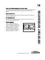
Voltage control (MIG mode)/Amperage control (stick mode)
This control is located on the upper front panel of the welder. It is used to adjust the welding voltage
when the MIG mode is engaged and to adjust the welding amperage when the stick mode is
engaged.
Output current indicator
This indicator is located on the upper front panel of the welder and glows when the welding unit is
providing enough power to weld.
Wire feed speed control
This control is located on the upper front panel of the welder and used to adjust the speed of the
wire being fed when in the MIG welding mode.
Polarity changing
For flux core welding (no shielding gas is
required) the MIG gun lead is connected to the
negative (“-”) terminal and the ground cable is
connected to the positive (“+”) terminal.
For MIG welding (solid wire) using shielding
gas, the MIG gun lead is connected to the
positive (“+”) terminal and the ground cable is
connected to the negative (“-”) terminal.
NO
GAS
GAS
MC-589306-06

IMPORTANT INFORMATION
15
MIG 180 INVERTER WELDER 058-9306-4
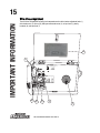
Wire drive compartment
The wire drive compartment has wire feed components such as drive tension adjustment knob (1),
drive tension arm (2), drive roll (3), MIG gun securement screw (4), set-up chart (5), polarity
terminals (6), and spool hub (7).
DCEN
DCEN
FLUX CORE WIRE
FIL AVEC ÂME EN FLUX
Courant continu polarité normale
Polarity switch setting:
Réglage du commutateur de polarité:
WARNING / AVERTISSEMENT
ELECTRIC SHOCK can kill
UN CHOC ÉLECTRIQUE peut tuer.
MOUING PARTS can cause injury.
LES PIÉCES MOBILES peuvent causer des blessures.
• Welding wire and drive parts may be at welding voltage.
• Keep away from moving parts.
• Ne vous approchez pas des pièces mobiles.
• Maintenez tous les couvercles, panneaus et portes fermés et
solidement en place.
• Keep all doors, covers and panels closed and securely in place.
• Le fil de soudure et les pièces motrices sont peut-être a la
tension de soudage.
• Ne touchez pas le fil oules parties motrices à mains nues ou
avec des outils lorsque la detente est sous, pression.
• Do not touch wire or drive parts with bare hands or tools when
trigger is depressed.
MIG
SPOOL GUN/PISTOLET À BOBINE
When normal MIG welding,
this switch should be turned in “MIG” position.
when using spool gun.
this switch should be in “Spool gun” position.
Ce commutateur doit être placé à la position « MIG »
si vous effectuez du soudage MIG normal
et à la position « SPOOL GUN »
si vous utilisez un pistolet à bobine.
Direct current, electrode nagative
DCEP
DCEP
MIG
MIG
Direct current, electrode positive
Courant continu, electrode positive
Polarity switch setting:
Réglage du commutateur de polarité:
STICK
BAGUETTE
Polarity switch setting:
Réglage du commutateur de polarité:
+
+
+
-
-
-
NO GAS/PAS DE GAZ
GAS/GAZ
1
2
4
7
3
6
5

IMPORTANT INFORMATION
16
MIG 180 INVERTER WELDER 058-9306-4
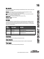
Gas selection
Different materials require different shielding gas when MIG welding. Refer to the set-up chart inside
the wire drive compartment.
Mild steel: Use 75% Argon and 25% for reduced spatter and reduced penetration for thinner
materials. Use CO
2
for deeper penetration and increased spatter.
Note: Do not use argon gas concentrations higher than 75% on steel. The result will be extremely
poor penetration, porosity, and brittleness of weld.
Stainless steel: Use a mixed gas consisting of Helium, Argon, and CO
2
.
Aluminum or bronze: Use 100% Argon.
Electrode
The welding electrode is a rod coated with a layer of flux. During the process of welding, electrical
current flows between the electrode (rod) and the grounded metal work piece. The intense heat of
the arc between the rod and the grounded metal melts the electrode and the flux. The most popular
electrodes are mentioned below:
Torch travel:
Refers to the movement of the welding torch along the weld joint.
Travel direction:
Refers to the direction of the torch moving along the weld joint in relation to the weld puddle.
Travel speed:
The rate at which the torch is being moved along the weld joint.
Type of
electrode
Tensile strength Application
E6011 60,000 PSI Deep penetration process
E6013 60,000 PSI Poor fitup application
E7014 70,000 PSI
High deposition and fast travel speed with light
penetration process
E7018AC 70,000 PSI Tack welding and out of position application
La page est en cours de chargement...
La page est en cours de chargement...
La page est en cours de chargement...
La page est en cours de chargement...
La page est en cours de chargement...
La page est en cours de chargement...
La page est en cours de chargement...
La page est en cours de chargement...
La page est en cours de chargement...
La page est en cours de chargement...
La page est en cours de chargement...
La page est en cours de chargement...
La page est en cours de chargement...
La page est en cours de chargement...
La page est en cours de chargement...
La page est en cours de chargement...
La page est en cours de chargement...
La page est en cours de chargement...
La page est en cours de chargement...
La page est en cours de chargement...
La page est en cours de chargement...
La page est en cours de chargement...
La page est en cours de chargement...
La page est en cours de chargement...
La page est en cours de chargement...
La page est en cours de chargement...
La page est en cours de chargement...
La page est en cours de chargement...
La page est en cours de chargement...
La page est en cours de chargement...
La page est en cours de chargement...
La page est en cours de chargement...
La page est en cours de chargement...
La page est en cours de chargement...
-
 1
1
-
 2
2
-
 3
3
-
 4
4
-
 5
5
-
 6
6
-
 7
7
-
 8
8
-
 9
9
-
 10
10
-
 11
11
-
 12
12
-
 13
13
-
 14
14
-
 15
15
-
 16
16
-
 17
17
-
 18
18
-
 19
19
-
 20
20
-
 21
21
-
 22
22
-
 23
23
-
 24
24
-
 25
25
-
 26
26
-
 27
27
-
 28
28
-
 29
29
-
 30
30
-
 31
31
-
 32
32
-
 33
33
-
 34
34
-
 35
35
-
 36
36
-
 37
37
-
 38
38
-
 39
39
-
 40
40
-
 41
41
-
 42
42
-
 43
43
-
 44
44
-
 45
45
-
 46
46
-
 47
47
-
 48
48
-
 49
49
-
 50
50
-
 51
51
-
 52
52
-
 53
53
-
 54
54


MasterCraft MIG 180 Manuel utilisateur
- Catégorie
- Système de soudage
- Taper
- Manuel utilisateur
dans d''autres langues
- English: MasterCraft MIG 180 User manual
Autres documents
-
Schumacher 98026053 Manuel utilisateur
-
Power Fist 8154700 Le manuel du propriétaire
-
HobartWelders TREK 180 Le manuel du propriétaire
-
-
-
Miller NA318521N Le manuel du propriétaire
-
-
-
-