
POWERED FOLD-DOWN
LIGHT AND ANTENNA BASE
6100 Series
SAVE THESE INSTRUCTIONS
#21421 INSTRUCTION MANUAL
PowerBase
EN

2
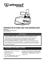
PowerBase
POWERED FOLD-DOWN LIGHT AND ANTENNA BASE
6100 Series
SAVE THESE INSTRUCTIONS
#21421 Rev A 0322
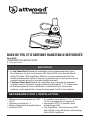
REQUIRED FOR INSTALLATION:
• 7/32" & 3/4" Drill Bits / Drive Sizes
• #2 Phillips Driver
• Marine Grade Sealant
• PTFE Lubricant
• 2x 1-1/4" Fender Washers and 10-24
Nuts (If Through-Hole Mounting)
• Attwood PowerBase Light is compatible with and solely designed for use with
Attwood LightArmor LED All-Round (5590 Series) and LED Masthead Lights
(7800 Series). If replacing a previously installed light, always remember to
replace it with one of at least the same pole length and rated visibility.
• Attwood PowerBase Antenna is compatible with most leading antennas up to
8ft in length that utilize industry standard 1"-14 threading and single mounting
points. Installing an antenna outside of this specification may result in damage to
unit and surroundings.
IMPORTANT
• 2-Position SPST Switch (with LED Backlight)
• PowerBase Light: LightArmor LED All-Round
(5590 Series) or Masthead/Anchor Light
(7800 Series)

3
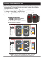
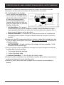
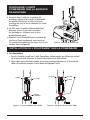
DETERMINE THE MOUNTING LOCATION OF POWERBASE
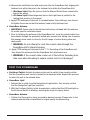
IMPORTANT: Please read through all installation steps prior to any actions to ensure safe
and compliant installation.
a. Utilizing the included mounting
template, identify a location on the
desired mounting surface that is
free of obstructions, and is as close
to level as possible. Take care to
ensure that the length of the pole
attachment is accounted for in
both the stowed and the deployed
position.
i. PowerBase Light: To ensure your navigation light is compliant; orient the
PowerBase unit along the fore and aft centerline of your vessel, so that the unit
stows or deploys towards the bow or the transom of the vessel.
ii. PowerBase Antenna: Orienting the unit further aft on the mounting surface
helps to mitigate any potential whip of the antenna in the
stowed state.
b. With the desired location identified, orient the mounting template so that the
attachment pole clearly stows and deploys towards the bow or the stern, depending
upon desired position.
i. WARNING: Failure to mount in this orientation will result in damage to the
PowerBase unit.
c. Once positioned, use the included mounting template to mark the mounting surface
for the following:
i. 2x Mounting Fastener Holes
ii. 1x Wire-Access Hole
iii. PowerBase Antenna: 1x Coaxial Cord Access Hole
d. Take the black rubber gasket and double check the position of the marked surface
to ensure proper alignment prior to drilling.
e. Remove the gasket, and drill the marked holes utilizing the recommended drill bits
above.

4
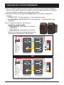
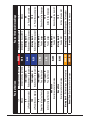
Figure A- PowerBase Wire Diagram
Recommended Installation:
• Switch A: 2-Position Switch (Backlit)
• Switch B: 3-Position Switch
See Blue Seas Systems Contura II Switches
for compatible switch offering.
WIRING THE POWERBASE UNIT
a. With at least 18-gauge marine grade wire, route the wires first through the gasket,
and then through the drilled wire-access hole to remove as much slack from above
the mounting surface as possible.
b. Utilize the included wiring diagram (Figure A) to connect the following…
i. 12V SWITCH (Two Position) – Positional Control
ii. PowerBase Light: 12V SWITCH (Three Position) – Navigation Light Control
Configuration 1
All-Round Light
(5590 Series)
DPDT
3-Pos Switch
Switch B
(Light Control)
12V System
Power
Switch A
(Position Control)
LED
SPST
2-Pos Switch
Seal or tie to GND
12V System
Power
Seal or tie to GND
Configuration 2
Masthead/Anchor Light
(7800 Series)
Switch B
(Light Control)
Switch A
(Position Control)
DPDT
3-Pos Switch
LED
SPST
2-Pos Switch
PowerBase Antenna: Seal/Tie to GND: Gray, White, and Brown
Wires, while otherwise following Switch A configuration.
OR

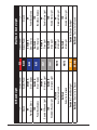
5
All-Round Light Masthead / Anchor Light
12V System Power RED System Power 12V
Ground System Power BLACK System Power Ground
0V
PowerBase Stows
Switch A:
Stow / Deploy BLUE Switch A
Stow / Deploy
0V
PowerBase Stows
12V
PowerBase Deploys
Switch A:
Stow / Deploy BLUE Switch A:
Stow / Deploy
12V
PowerBase Deploys
0V
Disable All-Round Light
Switch B:
All-Around Light GRAY Switch B
Stern Light
0V
Disable Stern Light
12V
Enable All-Round Light
Switch B:
All-Around Light GRAY Switch B:
Stern Light
12V
Enable Stern Light
Not Used
Seal or tie to Ground WHITE Switch B:
Mast Light
0V
Disable Mast Light
Not Used
Seal or tie to Ground WHITE Switch B:
Mast Light
12V
Enable Mast Light
Switch A: Switch Backlight ORANGE Switch A: Switch Backlight
Not Used – Seal or tie to Ground BROWN Not Used – Seal or tie to Ground

6
AFFIX THE POWERBASE UNIT TO
THE MOUNTING SURFACE
a. Prior to securing the unit to the mounting
surface, apply marine-grade sealant on the
mounting surface side of the gasket, as well
as the underside of the PowerBase Unit.
b. With sealant side down, place the gasket on
the mounting surface aligning with the pre-
drilled hole pattern.
c. Install the PowerBase unit overtop of the
gasket, securely fastening with the included
screws and plastic washers. See exploded
view in Figure B. Figure B - PowerBase Mounting
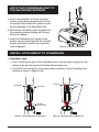
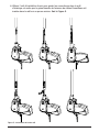
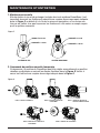
INSTALL ATTACHMENT TO POWERBASE
a. PowerBase Light
i. Prior to installing the pole to the PowerBase Unit, route the wires coming from the
bottom of the pole through the PowerBase Break Away hole.
ii. Connect the pin connectors to the associated receptacles on the PowerBase wire
harness as shown in Figure C & D.
BLACK
WHITE WIRE
WIRE
BLACK WIRE
RED WIRE
TO BE PLUGGED
WHITE WIRE
RED WIRE
Figure C - All-Around Light (5590 Series)
BLACK
WHITE WIRE
WIRE
BLACK WIRE
RED WIRE
TO BE PLUGGED
WHITE WIRE
RED WIRE
Figure D - Masthead Light (7800 Series)

7
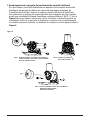
iii. Utilizing the included installation tool to guide the connectors into the light pole
so that the white jacket on the PowerBase wire harness is approximately an inch
into the pole. See Figure E.
Figure E - Pole Light Installation

8
a. Positional Switch: Activate the deploy state on the switch, then visually confirm
that the PowerBase unit has fully moved to the deployed state. Repeat this process
to return the unit to the stowed state.
b. PowerBase Light
i. Activate the on state from the Navigational Light switch, then visually confirm
that the Navigation Light has turned on.
ii. With the Positional Switch in the stowed state, confirm that the LED backlight on
the Positional Switch is blinking, denoting the ready-to-deploy status.
c. PowerBase Antenna
i. Confirm that the signal is being received by desired receiver. Please refer to the
antenna manufacturers instructions for signal quality troubleshooting.
TEST THE POWERBASE
iv. Remove the installation tool and insert pole into the PowerBase Unit, aligning the
fastener hole within the pole to the fastener hole within the PowerBase Unit.
1. Masthead Light: Align the pole so that the Attwood Shield faces towards the
bow of the vessel.
2. All-Round Light: Adjust alignment nut so that Light head is parallel to the
resting float position of the vessel.
v. Apply PTFE waterproof lubricant to included fastner, then utilizing a non-ferrous
bit tighten the screw so that the fastener head is fully bottomed out.
b. PowerBase Antenna
i. IMPORTANT: Please refer to the detailed instructions included with the antenna
for model specific installation steps.
ii. Prior to installing the antenna to the PowerBase Unit, route the coaxial cable from
the antenna through the previously drilled wire-access hole, taking care to ensure
that enough slack exists to allow for the full range of motion during stow and
deployment.
1. WARNING: Do not attempt to route the coaxial cable through the
PowerBase Unit’s internal housing.
iii. Apply PTFE waterproof lubricant to the 1”-14 threading of the PowerBase unit,
then thread the antenna onto the PowerBase Unit attachment arm.
1. WARNING: If the coaxial cable routes out of the bottom threading hole,
take care when threading to ensure coaxial cord is not damaged.

9
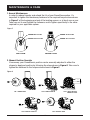
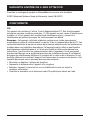
MAINTENANCE & CARE
1. Annual Maintenance
In order to reduce freeplay and extend the life of your PowerBase system, it’s
important to tighten the breakaway fasteners to the required torque values shown
in Figure F at the beginning and end of the boating season, or at least once a year.
Take care not to over tighten the fasteners, and to tighten specifically to the value
required for your applicable system.
TIGHTEN TO 5.2 FT-LBS
TIGHTEN TO 2.2 FT-LBS
LIGHT SYSTEM
TIGHTEN TO 2.2 FT-LBS
TIGHTEN TO 11 FT-LBS
ANTENNA SYSTEM
STEP 2: REMOVE SHEAR PIN
STEP 3: LINE UP HOLE WITH
BINDING POST HOLE
STEP 1: REMOVE COVER
STEP 5: REINSTALL COVER
STEP 4: REINSTALL SHEAR PIN
2. Manual Position Override
If necessary, your PowerBase’s position can be manually adjusted to either the
stowed or deployed position by following the steps shown in Figure G. Take care to
tighten the fasteners to the torque values shown in Figure F.
Figure F
Figure G

10
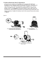
3. SafeGuard Breakaway Shear Pin Replacement
In the event of an impact your PowerBase unit is equipped with SafeGuard
Breakaway feature, helping minimize the damage to the Vessel, PowerBase, and
Light/Antenna. Once SafeGuard Breakaway has been engaged, you’ll need to
replace the shear pin with a new Attwood PowerBase Shear Pin (Attwood Part
Number: 6001-7). See Figure H for the steps needed to remove and install your
new shear pin. Take care not to discard the cover fastener during replacement, and
always remember to tighten the fasteners back to the required torque values shown
in Figure F.
STEP 2: LINE UP CENTER HOLE
WITH BINDING POST HOLE
STEP 1: REMOVE COVER, SHEAR PIN AND BINDING POST.
DISCARD BROKEN SHEAR PIN AND BINDING POST.
STEP 3: INSTALL NEW SHEAR PIN AND BINDING POST.
RE-INSTALL COVER.
STEP 2: LINE UP CENTER HOLE
WITH BINDING POST HOLE
STEP 1: REMOVE COVER, SHEAR PIN AND BINDING POST.
DISCARD BROKEN SHEAR PIN AND BINDING POST.
STEP 3: INSTALL NEW SHEAR PIN AND BINDING POST.
RE-INSTALL COVER.
Figure H

11
See product catalog or AttwoodMarine.com for details.
©2022 Advanced Systems Group by Brunswick, Lowell, MI 49331
COMPLIANCE
FCC
This device complies with part 15 of the FCC Rules. Operation is subject to the
following two conditions: (1) This device may not cause harmful interference, and
(2) this device must accept any interference received, including interference that
may cause undesired operation.
Note: This equipment has been tested and found to comply with the limits for
a Class B digital device, pursuant to part 15 of the FCC Rules. These limits are
designed to provide reasonable protection against harmful interference in a
residential installation. This equipment generates, uses and can radiate radio
frequency energy and, if not installed and used in accordance with the instructions,
may cause harmful interference to radio communications. However, there is
no guarantee that interference will not occur in a particular installation. If this
equipment does cause harmful interference to radio or television reception, which
can be determined by turning the equipment off and on, the user is encouraged to
try to correct the interference by one or more of the following measures:
• Reorient or relocate the receiving antenna.
• Increase the separation between the equipment and receiver.
• Connect the equipment into an outlet on a circuit different from that to which
the receiver is connected.
• Consult the dealer or an experienced radio/TV technician for help.
ATTWOOD LIMITED 5-YEAR WARRANTY

#21421 Rev A 0422

BASE DE FEU ET D’ANTENNE
RABATTABLE MOTORISÉE
Série 6100
CONSERVER CES INSTRUCTIONS
MANUEL D’INSTRUCTIONS N° 21421
PowerBase
FR

14
PowerBase
BASE DE FEU ET D'ANTENNE RABATTABLE MOTORISÉE
Série 6100
CONSERVER CES INSTRUCTIONS
N° 21421 Rév. A 0322
NÉCESSAIRE POUR L'INSTALLATION :
• Mèches/carrés conducteurs de 7/32"
et 3/4"
• Tournevis cruciforme n° 2
• Mastic d'étanchéité de qualité marine
• Lubrifiant PTFE
• Le Feu PowerBase Attwood est compatible et est exclusivement conçu pour
être utilisé avec les feux tout horizon à LED (Série 5590) et les feux de tête de
mât à LED (série 7800) LightArmor Attwood. Lors du remplacement d'un feu
installé précédemment, veillez à toujours le remplacer par un feu ayant au moins
la même longueur de mât et la même visibilité nominale.
• L'Antenne PowerBase Attwood est compatible avec la plupart des antennes
courantes jusqu'à 8 pieds de long qui utilisent un filetage de 1"-14 et des points
de fixation simples de norme industrielle. L'installation d'une antenne non
conforme à cette spécification risque d'endommager l'unité et ses alentours.
IMPORTANT
• 2 x rondelles de protection 1-1/4" et écrous
10-24 (si montage à trou traversant)
• Interrupteur SPST à 2 positions (avec
rétroéclairage LED)
• Feu PowerBase : Feu tout horizon à LED
(Série 5590) ou Feu de tête de mât/mouillage
(Série 7800) LightArmor

15
IMPORTANT : Veuillez lire attentivement toutes les étapes d'installation avant de
commencer afin d'assurer la sécurité et la conformité de l'installation.
a. À l'aide du gabarit de montage
fourni, identifiez un emplacement
sur la surface de montage désirée;
elle doit être libre de tout obstacle
et aussi proche que possible
de l'horizontale. Vérifiez que la
longueur de la fixation du mât est
prise en compte dans les positions
rabattue et déployée.
i. Feu PowerBase : Pour garantir
la conformité de votre feu de navigation, orientez l'unité PowerBase le long de
l'axe longitudinal du bateau, de sorte que l'unité se rabatte ou se déploie vers la
proue ou vers le tableau arrière du bateau.
ii. Antenne PowerBase : L'orientation de l'unité plus en arrière sur la surface de
montage permet de réduire le risque de fléchissement de l'antenne en position
rabattue.
b. Après avoir identifié l'emplacement désiré, orientez le gabarit de montage pour que
le mât se rabatte et se déploie clairement vers la proue ou la poupe, en fonction de
la position désirée.
i. AVERTISSEMENT : Si cette orientation de montage n'est pas respectée, l'unité
PowerBase sera endommagée.
c. Une fois en place, utilisez le gabarit de montage fourni pour marquer la surface de
montage pour les trous suivants :
i. 2 x trous de fixation de montage
ii. 1 x trou d'accès de câble
iii. Antenne PowerBase : 1 x trou d'accès de cordon coaxial
d. Prenez le joint en caoutchouc noir et vérifiez la position de la surface marquée pour
assurer un alignement correct avant de percer.
e. Retirez le joint et percez les trous marqués avec les mèches recommandées ci-
dessus.
IDENTIFICATION DE L'EMPLACEMENT DE MONTAGE DE L'UNITÉ POWERBASE
LES LIGNES EN POINTILLÉS
REPRÉSENTENT LA
GÉOMÉTRIE DU JOINT
LES HACHURES REPRÉSENTENT
LES 4 ZONES DE SUPPORT
MINIMUM INDIQUÉES
POSITION REPLIÉE
UTILISER LE GABARIT
AVEC CE CÔTÉ EN HAUT
TOUTES LES DIMENSIONS SONT EN POUCES
TROU DIMENSIONNÉ POUR BOULONNAGE TRAVERSANT
L'AXE CENTRAL DOIT ÊTRE PARALLÈLE À LA LIGNE
SUIVRE L'ÉTAPE D'INSTALLATION DU MANUEL D'UTILISATION.

16
Figure A - Schéma de câblage de l'unité PowerBase
Installation recommandée :
• Interrupteur A : Interrupteur à 2 positions
(rétroéclairé)
• Interrupteur B : Interrupteur à 3 positions
Vérifiez les interrupteurs compatibles parmi les
interrupteurs Contura II Blue Sea Systems
CÂBLAGE DE L'UNITÉ POWERBASE
a. Avec un câble de qualité marine de calibre 18 minimum, faites passer les câbles à
travers le joint, puis à travers le trou percé d'accès de câble pour éliminer autant de
mou que possible au-dessus de la surface de montage.
b. Utilisez le schéma de câblage fourni (Figure A) pour raccorder les éléments
suivants...
i. INTERRUPTEUR 12 V (deux positions) - Commande de position
ii. Feu PowerBase : INTERRUPTEUR 12 V (trois positions) - Commande de feu de
navigation
Configuration 1
Feu de navigation
(Série 5590)
DPDT
Interrupteur à
3 positions
Interrupteur B
(Position d'éclairage)
Alimentation de
système 12 V
Interrupteur A
(Position de commande)
LED
SPST
Interrupteur à
2 positions
Joint ou attache à la
masse
Alimentation de
système 12 V
Joint ou attache à la
masse
Configuration 2
Feu de tête de mât/antenne
(Serie 7800)
Interrupteur B
(Position d'éclairage)
Interrupteur A
(Position de commande)
DPDT
Interrupteur à
3 positions
LED
SPST
Interrupteur à
2 positions
Antenne PowerBase : Sceller/relier à la masse : câbles gris, blanc
et marron, autrement suivre la configuration de l'interrupteur A.
OU

17
Feu tout horizon Feu de tête de mât/mouillage
12 V Alimentation du système ROUGE Alimentation du système 12 V
Masse Alimentation du système NOIR Alimentation du système Masse
0 V
Le PowerBase se rabat
Interrupteur A :
Rabattement / Déploiement BLEU Interrupteur A :
Rabattement / Déploiement
0 V
Le PowerBase se rabat
12 V
Le PowerBase se déploie
Interrupteur A :
Rabattement / Déploiement BLEU Interrupteur A :
Rabattement / Déploiement
12 V
Le PowerBase se déploie
0 V
Désactive le feu tout horizon
Interrupteur B :
Feu tout horizon GRIS Interrupteur B :
Feu de poupe
0 V
Désactive le feu de poupe
12 V
Active le feu tout horizon
Interrupteur B :
Feu tout horizon GRIS Interrupteur B :
Feu de poupe
12 V
Active le feu de poupe
Non utilisé
Sceller ou relier à la masse BLANC Interrupteur B :
Feu de mât
0 V
Désactive le feu de mât
Non utilisé
Sceller ou relier à la masse BLANC Interrupteur B :
Feu de mât
12 V
Active le feu de mât
Interrupteur A : Rétroéclairage de l'interrupteur ORANGE Interrupteur A : Rétroéclairage de l'interrupteur
Non utilisé - Sceller ou relier à la masse MARRON Non utilisé - Sceller ou relier à la masse

18
FIXATION DE L'UNITÉ
POWERBASE SUR LA SURFACE
DE MONTAGE
a. Avant de fixer l'unité sur la surface de
montage, appliquez du mastic d'étanchéité
de qualité marine sur le côté surface de
montage du joint et sur le dessous de l'unité
PowerBase.
b. Le côté avec le mastic d'étanchéité étant
dessous, placez le joint sur la surface
de montage en l'alignant avec le trou
préalablement percé.
c. Installez l'unité PowerBase sur le dessus du
joint en la fixant solidement avec les vis et
les rondelles en plastique fournies. Voir la vue
éclatée dans la Figure B. Figure B - Montage du PowerBase
INSTALLATION DE L'ÉQUIPEMENT SUR LE POWERBASE
a. Feu PowerBase
i. Avant d'installer le mât sur l'unité PowerBase, faites passer les câbles qui sortent
de la base du mât à travers le trou de déconnexion du PowerBase.
ii. Raccordez les connecteurs mâles aux prises correspondantes sur le faisceau de
câbles PowerBase comme illustré dans les Figures C et D.
FIL NOIR
FIL BLANC
FIL NOIR
FIL ROUGE
À BRANCHER
FIL BLANC
FIL ROUGE
Figure C - Feu de navigation (Série 5590)
FIL NOIR
FIL BLANC
FIL NOIR
FIL ROUGE
À BRANCHER
FIL BLANC
FIL ROUGE
Figure D - Feu de tête de mât (Série 7800)

19
iii. Utilisez l'outil d'installation fourni pour guider les connecteurs dans le mât
d'éclairage, de sorte que la gaine blanche du faisceau de câbles PowerBase soit
insérée dans le mât sur un pouce environ. Voir la Figure E.
Figure E - Installation du feu de mât

20
a. Interrupteur de position : Activez le déploiement avec l'interrupteur, puis vérifiez
visuellement le mouvement de l'unité PowerBase en position complètement
déployée. Répétez cette procédure pour ramener l'unité en position rabattue.
b. Feu PowerBase
i. Activez la position d'allumage avec l'interrupteur de feu de navigation, puis
vérifiez visuellement que le feu de navigation s'est allumé.
ii. Avec l'interrupteur en position rabattue, vérifiez que le rétroéclairage LED sur
l'interrupteur de position clignote, indiquant que le feu est prêt au déploiement.
c. Antenne PowerBase
i. Vérifiez que le signal est reçu par le récepteur désiré. Consultez les instructions
du fabricant de l'antenne pour résoudre les problèmes de qualité du signal.
TEST DU POWERBASE
i. Retirez l'outil d'installation et introduisez le mât dans l'unité PowerBase en
alignant le trou de fixation à l'intérieur du mât avec le trou de fixation à l'intérieur
de l'unité PowerBase.
1. Feu de tête de mât : Alignez le mât de sorte que le carter de protection
Attwood soit dirigé vers la proue du bateau.
2. Feu tout horizon : Réglez l'écrou d'alignement de sorte que la tête du feu soit
parallèle à la position de flottaison du bateau au repos.
ii. Appliquez du lubrifiant étanche PTFE sur la fixation incluse, puis utilisez une
mèche non ferreuse pour serrer la vis de sorte que la tête de la vis touche le
fond.
a. Antenne PowerBase
i. IMPORTANT : Consultez les instructions détaillées fournies avec l'antenne pour
suivre les étapes d'installation spécifiques au modèle.
ii. Avant d'installer l'antenne sur l'unité PowerBase, faites passer le câble coaxial
de l'antenne à travers le trou d'accès de câble préalablement percé, en veillant
à laisser suffisamment de mou pour permettre une amplitude de mouvement
complète pendant le rabattement et le déploiement.
1. AVERTISSEMENT : N'essayez pas de faire passer le câble coaxial à
travers le boîtier interne de l'unité PowerBase.
iii. Appliquez du lubrifiant étanche PTFE sur le filetage 1"-14 de l'unité PowerBase,
puis installez l'antenne sur le bras de fixation de l'unité PowerBase.
1. AVERTISSEMENT : Si le câble coaxial sort du trou fileté inférieur, faites
attention pendant l'installation pour éviter d'endommager le cordon
coaxial.
La page charge ...
La page charge ...
La page charge ...
La page charge ...
-
 1
1
-
 2
2
-
 3
3
-
 4
4
-
 5
5
-
 6
6
-
 7
7
-
 8
8
-
 9
9
-
 10
10
-
 11
11
-
 12
12
-
 13
13
-
 14
14
-
 15
15
-
 16
16
-
 17
17
-
 18
18
-
 19
19
-
 20
20
-
 21
21
-
 22
22
-
 23
23
-
 24
24


dans d''autres langues
- English: Attwood 6100-LT-7 User manual
Documents connexes
Autres documents
-
AEG POWERBASE 60 Le manuel du propriétaire
-
 Scalextric digital ADVANCED 6 CAR POWERBASE Manuel utilisateur
-
Kenwood JKP230 Le manuel du propriétaire
-
Kenwood SJM350 Le manuel du propriétaire
-
Kenwood SKM34 Le manuel du propriétaire
-
Kenwood JKP350 Le manuel du propriétaire
-
Leviton OPBCA-W Guide d'installation
