Shelly 2 Circuit WiFi Relay Switch Mode d'emploi
- Taper
- Mode d'emploi

EN
USER AND SAFETY GUIDE
2 CIRCUIT WI-FI RELAY SWITCH WITH
POWER MEASUREMENT AND COVER
CONTROL CAPABILITY
Read before use
This document contains important technical and safety in-
formation about the device, its safety use and installation.
⚠CAUTION! Before beginning the installation, please read
this guide and any other documents accompanying the device
carefully and completely. Failure to follow the installation pro-
cedures could lead to malfunction, danger to your health and
life, violation of the law or refusal of legal and/or commercial
guarantee (if any). Allterco Robotics EOOD is not responsible
for any loss or damage in case of incorrect installation or im-
proper operation of this device due to failure of following the
user and safety instructions in this guide.
Product Introduction
Shelly® is a line of innovative microprocessor-managed
devices, which allow remote control of electric appliances
through a mobile phone, tablet, PC, or home automation
system. Shelly® devices can work standalone in a local Wi-Fi
network or they can also be operated through cloud home
automation services. Shelly Cloud is such a service that can
be accessed using either Android or iOS mobile application,
or with any internet browser at https://home.shelly.cloud/.
Shelly® devices can be accessed, controlled and monitored
remotely from any place where the User has internet connec-
tivity, as long as the devices are connected to a Wi-Fi router
and the Internet. Shelly® devices have embedded Web Inter-
face accessible at http://192.168.33.1 in the Wi Fi network,
created by the device in Access Point mode, or at the URL
address of the device in the Wi-Fi network it is connected to.
The embedded Web Interface can be used to monitor and
control the device, as well as adjust its settings.
Shelly® devices can communicate directly with other Wi-Fi
devices through HTTP protocol. An API is provided by Allter-
co Robotics EOOD. For more information, please visit:
https://shelly-api-docs.shelly.cloud/#shelly-family-overview
.
Shelly® devices are delivered with factory-installed rmware.
If rmware updates are necessary to keep the devices in con-
formity, including security updates, Allterco Robotics EOOD
will provide the updates free of charge through the device
embedded Web Interface or Shelly Mobile Application, where
the information about the current rmware version is avail-
able. The choice to install or not the Device rmware updates
is User’s sole responsibility. Allterco Robotics EOOD shall not
be liable for any lack of conformity of the Device caused by
failure of the User to install the provided updates in a timely
manner.
Shelly® Plus line offers PM products capable of real-time
precise power measurement.
Control your home with your voice
Shelly® devices are compatible with Amazon Alexa and Goo-
gle Home supported functionalities. Please see our step-by-
step guide on: https://shelly.cloud/support/compatibility/.
Schematics
See the schematics at the begining of the user guide.
Legend
Device terminals:
• O1: Load circuit 1 output terminal
• O2: Load circuit 2 output terminal
• S1: Switch (controlling O1) input terminal
• S2: Switch (controlling O2) input terminal
• L: Live (110-240 VAC) terminals
• N: Neutral terminal
• : 24 VDC positive terminal
• : 24 VDC negative terminal
Cables:
• N: Neutral cable
• L: Live (110-240 VAC) cable
• +: 24 VDC positive cable
• -: 24 VDC negative cable
Installation Instructions
Shelly® Plus 2PM (the Device) can control 2 electrical cir-
cuits, including a bi-directional AC motor. Each circuit can be
loaded up to 10 A (16 A total for both circuits) and its power
consumption can be measured individually (AC only). It can
be retrotted into a standard in-wall console, behind power
sockets and light switches or other places with limited space.
⚠CAUTION! Danger of electrocution. Mounting/installation
of the Device to the power grid has to be performed with cau-
tion, by a qualied electrician.
⚠CAUTION! Danger of electrocution. Every change in the
connections has to be done after ensuring there is no voltage
present at the Device terminals.
⚠CAUTION! Use the Device only with a power grid and ap-
pliances which comply with all applicable regulations. A short
circuit in the power grid or any appliance connected to the De-
vice may damage the Device.
⚠CAUTION! Do not connect the Device to appliances ex-
ceeding the given max load!
⚠CAUTION! Connect the Device only in the way shown in
these instructions. Any other method could cause damage
and/or injury.
⚠CAUTION! Do not install the device at a place that is pos-
sible to get wet.
⚠RECOMMENDATION Connect the Device using solid sin-
gle-core cables with increased insulation heat resistance not
less than PVC T105°C.
Before starting installing/mounting the Device, wire check
that the breakers are turned off and there is no voltage on
their terminals. This can be done with a phase meter or mul-
timeter. When you are sure that there is no voltage, you can
proceed to connecting the cables.
If you want to use the Device as a relay switch to control 2
load circuits, connect the Device as shown on Fig. 1 for AC
circuits and on Fig. 2 for DC circuits.
⚠CAUTION! Use the same power supply for the two load
circuits and the Device.
For AC circuits connect both L terminals to the Live cable
and the N terminal to the Neutral cable. Connect the rst load
circuits to the O1 terminal and the Neutral cable. Connect
the second load circuits to the O2 terminal and the Neutral
cable. Connect the rst switch to the S1 terminal and the Live
cable. Connect the second switch to the S2 terminal and the
Live cable.
For DC circuits connect both L terminals to the Negative
cable and the N terminal to the Positive cable. Connect the
rst load circuits to the O1 terminal and the Positive cable.
Connect the second load circuits to the O2 terminal and the
Positive cable. Connect the rst switch to the S1 terminal and
the Negative cable. Connect the second switch to the S2 ter-
minal and the Negative cable.
⚠RECOMMENDATION: For inductive appliances that cause
voltage spikes during switching on/off, such as electrical
motors, fans, vacuum cleaners and similar ones, RC snubber
(0.1µF / 100Ω / 1/2W / 600V AC) should be connected parallel
to the appliance.
The RC snubber can be purchased at
https://shop.shelly.cloud/rc-snubber-wi-smart-home-automation
As a cover controller Shelly® Plus 2PM can work in 3 modes:
detached, single input or dual input.
In detached mode, the Device can be controlled through its
WebUI and the App only. Even if buttons or switches are con-
nected to the Device, they will not be allowed to control the
motor rotation in detached mode.
If you want to use the Device in detached mode connect the
device as shown on Fig. 3: Connect both L terminals to the
Live cable and the N terminal to the Neutral cable. Connect
the common motor terminal/cable to the Neutral cable.
Connect motor direction terminals/cables to the O1 and O2
terminals.*
If you want to use the Device in single input mode connect
the device as shown on Fig. 4 for a button input or Fig. 5 for
a switch input. Connect both L terminals to the Live cable
and the N terminal to the Neutral cable. Connect the common
motor terminal/cable to the Neutral cable. Connect motor di-
rection terminals/cables to the O1 and O2 terminals*.
Connect the button or the switch to the S1 or the S2 terminal
and the Live cable.
If the input is congured as a button in the Device settings,
each button press cycles open, stop, close, stop...
If the input is congured as a switch, each switch toggle cy-
cles open, stop, close, stop...
In single input mode Shelly® Plus 2PM provides safety
switch functionality. To utilize it, connect the device as shown
on Fig. 6 for a button input or Fig. 7 for a switch input. Con-
nect both L terminals to the Live cable and the N terminal to
the Neutral cable. Connect the common motor terminal/ca-
ble to the Neutral cable. Connect motor direction terminals/
cables to the O1 and O2 terminals*.
Connect the controlling button or switch to the S1 terminal
and the Live cable. Connect the safety switch to the S2 termi-
nal and the Live cable.
DE
BENUTZER- UND
SICHERHEITSHANDBUCH
WI-FI-RELAISSCHALTER
MIT 2 SCHALTKREISEN,
LEISTUNGSMESSUNG UND
ABDECKUNGSSTEUERUNG
Vor Benutzung lesen
Dieses Dokument enthält wichtige technische und sicher-
heitstechnische Informationen über das Gerät und seine
sichere Verwendung und Installation.
⚠ACHTUNG! Bevor Sie mit der Installation beginnen, lesen
Sie bitte die Begleitdokumentation sorgfältig und vollständig
durch. Die Nichtbeachtung der empfohlenen Verfahren kann
zu Fehlfunktionen, Lebensgefahr oder Gesetzesverstößen
führen. Allterco Robotics EOOD haftet nicht für Verluste oder
Schäden im Falle einer falschen Installation oder Bedienung
dieses Geräts.
Produkt-Einführung
Shelly® ist eine Reihe innovativer, mikroprozessorgesteu-
erter Geräte, die die Fernsteuerung von Elektrogeräten über
ein Mobiltelefon, ein Tablet, einen PC oder ein Hausauto-
matisierungssystem ermöglichen. Shelly® Geräte können
eigenständig in einem lokalen Wi-Fi-Netzwerk arbeiten oder
sie können auch über Cloud-Dienste für die Hausautoma-
tion betrieben werden. Shelly Cloud ist ein solcher Dienst,
auf den entweder über eine Android- oder iOS-Mobilan-
wendung oder über einen beliebigen Internetbrowser unter
https://home.shelly.cloud/ zugegriffen werden kann. Shelly®
Geräte können von jedem Ort aus, an dem der Benutzer eine
Internetverbindung hat, angesprochen, gesteuert und über-
wacht werden, solange die Geräte mit einem Wi-Fi-Router und
dem Internet verbunden sind. Shelly® Geräte verfügen über
ein integriertes Web-Interface, das unter http://192.168.33.1
im Wi-Fi-Netzwerk zugänglich ist, das vom Gerät im Access
Point-Modus erstellt wird, oder unter der URL-Adresse des
Geräts im Wi-Fi-Netzwerk, mit dem es verbunden ist. Das
integrierte Web-Interface kann zur Überwachung und Steue-
rung des Geräts sowie zur Anpassung seiner Einstellungen
verwendet werden.
Shelly® Geräte können direkt mit anderen Wi-Fi-Geräten über
das HTTP-Protokoll kommunizieren. Eine API wird von Allter-
co Robotics EOOD bereitgestellt. Für weitere Informationen
besuchen Sie bitte:
https://shelly-api-docs.shelly.cloud/#shelly-family-overview
.
Shelly® Geräte werden mit werkseitig installierter Firmware
geliefert. Wenn Firmware-Updates erforderlich sind, um die
Geräte konform zu halten, einschließlich Sicherheitsupdates,
stellt Allterco Robotics EOOD die Updates kostenlos über die
in das Gerät eingebettete Webschnittstelle oder die Shelly
Mobile Application zur Verfügung, wo die Informationen über
die aktuelle Firmware-Version verfügbar sind. Die Entschei-
dung, die Firmware-Updates des Geräts zu installieren oder
nicht, liegt in der alleinigen Verantwortung des Benutzers.
Allterco Robotics EOOD haftet nicht für Konformitätsmängel
des Geräts, die darauf zurückzuführen sind, dass der Benut-
zer die bereitgestellten Updates nicht rechtzeitig installiert
hat.
Shelly® Plus bietet PM-Produkte, die eine präzise Leistungs-
messung in Echtzeit ermöglichen.
Steuern Sie Ihr Zuhause mit Ihrer Stimme
Shelly® Geräte sind mit den von Amazon Alexa und Google
Home unterstützten Funktionalitäten kompatibel. Bitte sehen
Sie sich unsere Schritt-für-Schritt-Anleitung an:
https://shelly.cloud/support/compatibility/.
Schaltpläne
Siehe die Schaltpläne am Anfang des Benutzerhandbuchs.
Legende
Geräteklemmen:
• O1: Ausgangsklemme des Lastkreises 1
• O2: Ausgangsklemme des Lastkreises 2
• S1: Eingangsklemme des Schalters (zur Steuerung von O1)
• S1: Eingangsklemme des Schalters (zur Steuerung von O2)
• L: Stromführende Klemmen (110-240 VAC)
• N: Neutrale Klemme
• : 24 VDC positive Klemme
• : 24 VDC Minusklemme
Kabel:
• N: Neutrales Kabel
• L: Stromführendes Kabel (110-240 VAC)
• +: 24 VDC Pluskabel
• -: 24 VDC Minuskabel
Installationsanleitung
Der Shelly® Plus 2PM (das Gerät) kann 2 Stromkreise steu-
ern, darunter einen bidirektionalen AC-Motor. Jeder Strom-
kreis kann mit bis zu 10 A belastet werden (16 A insgesamt
für beide Stromkreise) und sein Stromverbrauch kann in-
dividuell gemessen werden (nur AC). Es kann nachträglich
in eine Standard-Unterputzkonsole, hinter Steckdosen und
Lichtschaltern oder an anderen Stellen mit wenig Platz ein-
gebaut werden.
⚠VORSICHT! Gefahr eines Stromschlages. Die Montage/In-
stallation des Geräts an das Stromnetz muss von einem quali-
zierten Elektriker mit Vorsicht durchgeführt werden.
⚠VORSICHT! Es besteht Stromschlaggefahr. Bei jeder Ände-
rung der Anschlüsse muss sichergestellt werden, dass an den
Klemmen des Geräts keine Spannung anliegt.
⚠VORSICHT! Verwenden Sie das Gerät nur mit einem
Stromnetz und Geräten, die allen geltenden Vorschriften ent-
sprechen. Ein Kurzschluss im Stromnetz oder in einem an das
Gerät angeschlossenen Gerät kann das Gerät beschädigen.
⚠VORSICHT! Schließen Sie das Gerät nicht an Geräte an, die
die angegebene Höchstlast überschreiten!
⚠VORSICHT! Schließen Sie das Gerät nur auf die in dieser
Anleitung beschriebene Weise an. Jede andere Methode kann
zu Schäden und/oder Verletzungen führen.
⚠VORSICHT! Installieren Sie das Gerät nicht an einem Ort,
an dem es nass werden kann.
⚠EMPFEHLUNG Schließen Sie das Gerät mit massiven ein-
adrigen Kabeln mit erhöhter Isolationswärmebeständigkeit
von mindestens PVC T105°C an.
Bevor Sie mit der Installation/Montage des Geräts beginnen,
prüfen Sie, ob die Unterbrecher ausgeschaltet sind und keine
Spannung an den Klemmen anliegt. Dies kann mit einem Pha-
senmesser oder Multimeter erfolgen. Wenn Sie sicher sind,
dass keine Spannung anliegt, können Sie mit dem Anschluss
der Kabel fortfahren.
Wenn Sie das Gerät als Relaisschalter zur Steuerung von 2
Lastkreisen verwenden möchten, schließen Sie das Gerät wie
in Abb. 1 für Wechselstromkreise und in Abb. 2 für Gleich-
stromkreise dargestellt an.
⚠VORSICHT! Verwenden Sie für die beiden Lastkreise und
das Gerät die gleiche Spannungsversorgung.
Bei Wechselstromkreisen schließen Sie beide Klemmen L an
das stromführende Kabel und die Klemme N an das neutra-
le Kabel an. Schließen Sie den ersten Laststromkreis an die
Klemme O1 und das Nullleiterkabel an. Schließen Sie den
zweiten Laststromkreis an die Klemme O2 und das Nulllei-
terkabel an. Schließen Sie den ersten Schalter an die Klem-
me S1 und das stromführende Kabel an. Schließen Sie den
zweiten Schalter an die Klemme S2 und das stromführende
Kabel an.
Bei Gleichstromkreisen schließen Sie beide Klemmen L an
das Minuskabel und die Klemme N an das Pluskabel an.
Schließen Sie die ersten Lastkreise an die Klemme O1 und
das Pluskabel an. Schließen Sie die zweiten Lastkreise an
die Klemme O2 und das Pluskabel an. Schließen Sie den
ersten Schalter an die Klemme S1 und das Minuskabel an.
Schließen Sie den zweiten Schalter an die Klemme S2 und
das Minuskabel an.
⚠EMPFEHLUNG: Bei induktiven Geräten, die beim Ein- und
Ausschalten Spannungsspitzen verursachen, wie z.B. Elektro-
motoren, Ventilatoren, Staubsauger und ähnliche, sollte ein
RC-Dämpfer (0,1µF / 100Ω / 1/2W / 600V AC) parallel zum
Gerät angeschlossen werden.
Der RC-Snubber kann erworben werden unter
https://shop.shelly.cloud/rc-snubber-wi-smart-home-automation
Als Abdeckungsregler kann Shelly® Plus 2PM in 3 Modi
arbeiten: freistehend, mit einem Eingang oder mit zwei Ein-
gängen.
Im getrennten Modus kann das Gerät nur über seine WebUI
und die App gesteuert werden. Selbst wenn Taster oder
Schalter an das Gerät angeschlossen sind, können sie die
Motordrehung im getrennten Modus nicht steuern.
Wenn Sie das Gerät im getrennten Modus verwenden möch-
ten, schließen Sie es wie in Abb. 3 gezeigt an: Verbinden Sie
beide L-Klemmen mit dem stromführenden Kabel und die N-
Klemme mit dem neutralen Kabel. Verbinden Sie die gemein-
samen Motorklemmen/-kabel mit dem Nullleiter. Schließen
Sie die Klemmen/Kabel für die Motorrichtung an die Klem-
men O1 und O2 an.*
Wenn Sie das Gerät im Einzeleingangsmodus verwenden
möchten, schließen Sie es wie in Abb. 4 für einen Tasterein-
gang oder Abb. 5 für einen Schaltereingang dargestellt an.
Schließen Sie die beiden Klemmen L an das stromführende
IT
GUIDA ALL’USO E ALLA SICUREZZA
INTERRUTTORE A RELÈ WI-FI A
2 CIRCUITI CON CAPACITÀ DI
MISURAZIONE DELLA POTENZA E
CONTROLLO DELLA COPERTURA
Leggere prima dell’uso
Questo documento contiene importanti informazioni tecni-
che e di sicurezza sul dispositivo e sul suo uso e installa-
zione in sicurezza.
⚠ATTENZIONE! Prima di iniziare l’installazione leggere at-
tentamente e completamente la documentazione allegata.
La mancata osservanza delle procedure consigliate potrebbe
portare a malfunzionamenti, pericolo per la vita o violazione
della legge. Allterco Robotics EOOD non è responsabile per
eventuali perdite o danni in caso di installazione o funziona-
mento errati di questo dispositivo.
Introduzione al prodotto
Shelly® è una linea di dispositivi innovativi gestiti da micro-
processori che permettono il controllo remoto degli elettro-
domestici attraverso un telefono cellulare, un tablet, un PC
o un sistema domotico. I dispositivi Shelly® sono in grado
di funzionare autonomamente in una rete Wi-Fi locale o pos-
sono anche essere gestiti attraverso servizi di automazione
domestica cloud. Shelly Cloud è un servizio di questo tipo
a cui si può accedere utilizzando un’applicazione mobile An-
droid o iOS o con qualsiasi browser internet su https://home.
shelly.cloud/. I dispositivi Shelly® sono accessibili, con-
trollati e monitorati a distanza da qualsiasi luogo in cui
l’utente abbia una connettività Internet, purché i dispositivi
siano collegati a un router Wi-Fi e a Internet. I dispositivi
Shelly® hanno un’interfaccia web incorporata accessibile a
http://192.168.33.1 nella rete Wi Fi, creata dal dispositivo in
modalità Access Point, o all’indirizzo URL del dispositivo nel-
la rete Wi-Fi a cui è connesso. L’interfaccia web incorporata
può essere utilizzata per monitorare e controllare il dispositi-
vo, così come per regolare le sue impostazioni.
I dispositivi Shelly® sono in grado di comunicare direttamen-
te con altri dispositivi Wi-Fi attraverso il protocollo HTTP.
Un’API è fornita da Allterco Robotics EOOD. Per maggiori
informazioni, visitare:
https://shelly-api-docs.shelly.cloud/#shelly-family-overview
.
I dispositivi Shelly® vengono consegnati con un rmware in-
stallato in fabbrica. Se sono necessari aggiornamenti del r-
mware per mantenere i dispositivi in conformità, compresi gli
aggiornamenti di sicurezza, Allterco Robotics EOOD fornirà
gli aggiornamenti gratuitamente attraverso l’interfaccia web
incorporata del dispositivo o l’applicazione mobile Shelly,
dove sono disponibili le informazioni sulla versione corrente
del rmware. La scelta di installare o meno gli aggiornamen-
ti del rmware del dispositivo è di esclusiva responsabilità
dell’utente. Allterco Robotics EOOD non è responsabile per
qualsiasi mancanza di conformità del dispositivo causata
dalla mancata installazione degli aggiornamenti forniti dall’u-
tente in modo tempestivo.
La linea Shelly® Plus offre prodotti PM in grado di misurare
con precisione la potenza in tempo reale.
Controlla la tua casa con la tua voce
I dispositivi Shelly® sono compatibili con le funzionalità sup-
portate da Amazon Alexa e Google Home. Consulta la nostra
guida passo dopo passo su:
https://shelly.cloud/support/compatibility/.
Schemi
Vedi gli schemi all’inizio della guida utente.
Legenda
Terminali del dispositivo:
• O1: Terminale di uscita del circuito di carico 1
• O2: Terminale di uscita del circuito di carico 2
• S1: Terminale d’ingresso dell’interruttore (che controlla
O1)
• S2: Terminale d’ingresso dell’interruttore (che controlla
O2)
• L: Terminali sotto tensione (110-240 VAC)
• N: Terminale neutro
• : 24 VDC terminale positivo
• : 24 VDC terminale negativo
Cavi:
• N: Cavo neutro
• L: Cavo sotto tensione (110-240 VAC)
• +: Cavo positivo 24 VDC
• -: Cavo negativo a 24 VDC
Istruzioni per l’installazione
Shelly® Plus 2PM (il dispositivo) è in grado di controllare 2
circuiti elettrici, incluso un motore AC bidirezionale. Ogni cir-
cuito può essere caricato no a 10 A (16 A totali per entrambi
i circuiti) e il suo consumo energetico può essere misurato in-
dividualmente (solo AC). Può essere installato in una console
standard a muro, dietro le prese di corrente e gli interruttori
della luce o in altri luoghi con spazio limitato.
⚠ATTENZIONE! Pericolo di folgorazione. Il montaggio/in-
stallazione del dispositivo alla rete elettrica deve essere ese-
guito con cautela da un elettricista qualicato.
⚠ATTENZIONE! Pericolo di folgorazione. Ogni modica dei
collegamenti deve essere effettuata dopo essersi assicurati
che non ci sia tensione ai morsetti dell’apparecchio.
⚠ATTENZIONE! Utilizzare l’apparecchio solo con una rete
elettrica e con apparecchi conformi a tutte le norme vigenti.
Un cortocircuito nella rete elettrica o in qualsiasi apparecchio
collegato all’apparecchio può danneggiare l’apparecchio.
⚠ATTENZIONE! Non collegare l’apparecchio ad apparecchi
che superano il carico massimo indicato!
⚠ATTENZIONE! Collegare l’apparecchio solo nel modo in-
dicato in queste istruzioni. Qualsiasi altro metodo potrebbe
causare danni e/o lesioni.
⚠ATTENZIONE! Non installare il dispositivo in un luogo che
possa bagnarsi.
⚠RACCOMANDAZIONE Collegare il dispositivo utilizzando
cavi unipolari solidi con una maggiore resistenza termica
dell’isolamento non inferiore a PVC T105°C.
Prima di iniziare l’installazione/montaggio del dispositivo,
controllare che gli interruttori siano spenti e che non ci sia
tensione sui loro terminali. Questo può essere fatto con un
misuratore di fase o un multimetro. Quando siete sicuri che
non c’è tensione, potete procedere al collegamento dei cavi.
Se vuoi utilizzare il dispositivo come un interruttore a relè
per controllare 2 circuiti di carico, collega il dispositivo come
mostrato in Fig. 1 per i circuiti AC e in Fig. 2 per i circuiti DC.
⚠ATTENZIONE! Usare la stessa alimentazione per i due cir-
cuiti di carico e per il dispositivo.
Per i circuiti CA, collegare entrambi i terminali L al cavo sot-
to tensione e il terminale N al cavo neutro. Collegare i primi
circuiti di carico al terminale O1 e al cavo neutro. Collegare
i secondi circuiti di carico al terminale O2 e al cavo neutro.
Collegare il primo interruttore al terminale S1 e al cavo sotto
tensione. Collegare il secondo interruttore al terminale S2 e
al cavo sotto tensione.
Per i circuiti CC, collegare entrambi i terminali L al cavo ne-
gativo e il terminale N al cavo positivo. Collegare i primi cir-
cuiti di carico al terminale O1 e al cavo positivo. Collegare i
secondi circuiti di carico al terminale O2 e al cavo positivo.
Collegare il primo interruttore al terminale S1 e al cavo ne-
gativo. Collegare il secondo interruttore al terminale S2 e al
cavo negativo.
⚠RACCOMANDAZIONE: Per gli apparecchi induttivi che
causano picchi di tensione durante l’accensione/spegnimen-
to, come motori elettrici, ventilatori, aspirapolvere e simili, lo
snubber RC (0,1µF / 100Ω / 1/2W / 600V AC) dovrebbe essere
collegato in parallelo all’apparecchio.
Lo snubber RC può essere acquistato su
https://shop.shelly.cloud/rc-snubber-wi-smart-home-automation
Come controller di copertura Shelly® Plus 2PM può funzio-
nare in 3 modalità: distaccato, a singolo ingresso o a doppio
ingresso.
In modalità distaccata, l’apparecchio può essere controllato
solo attraverso la sua WebUI e l’App. Anche se all’apparec-
chio sono collegati pulsanti o interruttori, questi non potran-
no controllare la rotazione del motore in modalità distaccata.
Se si desidera utilizzare il dispositivo in modalità distaccata,
collegare il dispositivo come mostrato in Fig. 3: Collegare en-
trambi i terminali L al cavo Live e il terminale N al cavo Neu-
tral. Collegare il terminale/cavo comune del motore al cavo
Neutro. Collegare i terminali/cavi della direzione del motore
ai terminali O1 e O2.*
Se si desidera utilizzare il dispositivo in modalità ingresso
singolo, collegare il dispositivo come mostrato in Fig. 4 per
un ingresso pulsante o in Fig. 5 per un ingresso interruttore.
Collegare entrambi i terminali L al cavo Live e il terminale N al
cavo Neutral. Collegare il terminale/cavo comune del motore
al cavo neutro. Collegare i terminali/cavi della direzione del
motore ai terminali O1 e O2*.
Collegare il pulsante o l’interruttore al terminale S1 o S2 e al
cavo sotto tensione.
Se l’ingresso è congurato come un pulsante nelle imposta-
zioni del dispositivo, ogni pressione del pulsante fa un ciclo
di apertura, arresto, chiusura, arresto...
The safety switch can be congured to:
- Stop the movement until the safety switch is disengaged
or until a command is sent** and, if allowed in the Device
settings, the movement is resumed in the opposite direction
until the end position is reached.
- Stop and immediately reverse the movement until the end
position is reached. This option requires reverse movement
to be allowed in the Device settings.
The safety switch can also be congured to stop the move-
ment in only one of the directions or in both.
If you want to use the Device in dual input mode, connect the
device as shown on Fig. 8 for a button inputs or Fig. 9 for a
switch inputs. Connect both L terminals to the Live cable and
the N terminal to the Neutral cable.
Connect the common motor terminal/cable to the Neutral
cable. Connect motor direction terminals/cables to the O1
and O2 terminals*.
Connect the rst button/switch to the S1 terminal and the
Live cable. Connect the second button/switch to the S2 ter-
minal and the Live cable.
In case the inputs are congured as buttons:
- Pressing a button when the cover is static, moves the cover
in the corresponding direction until the endpoint is reached.
- Pressing the button for the same direction while the cover
is moving, stops the cover.
- Pressing the button for the opposite direction, while the cov-
er is moving, reverses the cover movement until the endpoint
is reached.
In case the inputs are congured as switches:
- Turning a switch on moves the cover in the corresponding
direction until an endpoint is reached.
- Turning the switch off stops the cover movement.
If both switches are turned on, Shelly® Plus 2PM will respect
the last engaged switch. Turning off the last engaged switch
stops the cover movement, even if the other switch is still on.
To move the cover in the opposite direction, the other switch
has to be turned off and on again.
Shelly® Plus 2PM can detect obstacles. If an obstacle is
present, the cover movement will be stopped and, if cong-
ured so in the Device settings, reversed until the endpoint is
reached. Obstacle detection can be enabled or disabled for
only one of the directions or for both.
Troubleshooting
In case you encounter problems with the installation or oper-
ation of Shelly® Plus 2PM, please check its knowledge base
page:
www.shelly.cloud/knowledge-base/devices/shelly-plus-2pm/
*The Device outputs can be recongured to match the required
rotation direction.
**Interaction with the button, the switch or a control in the
WebUI or in the App (has to command the cover in the op-
posite to the direction before the safety switch engagement)
Initial Inclusion
If you choose to use the Device with the Shelly Cloud mo-
bile application and Shelly Cloud service, instructions how to
connect the Device to the Cloud and control it through the
Shelly App can be found in the “App Guide”. Shelly Mobile
Application and Shelly Cloud service are not conditions for
the Device proper functioning. This Device can be used with
various other home automation services and applications.
⚠CAUTION! Do not allow children to play with the buttons/
switches connected to the Device. Keep the Devices for re-
mote control of Shelly (mobile phones, tablets, PCs) away
from children.
Specications
• Dimensions (HxWxD): 41x36x17 mm
• Power supply: 110 - 240 VAC, 50/60 Hz or 24 VDC ±10%
• Power metering: Yes
• Cover mode: Yes
• Electrical consumption: < 1.4 W
• Working temperature: -20°C - 40 °C
• Controlling elements: 2 relays
• Controlled elements: 2 circuits or a bi-directional AC motor
• Max switching voltage: 240 VAC / 30 VDC
• Max current per channel: 10 A
• Total max current: 16 A
• Dry contacts: No
• Temperature Protection: Yes
• Wi-Fi: Yes
• Bluetooth: Yes
• Radio protocol: Wi-Fi 802.11 b/g/n
• Radio signal power: 1 mW
• Frequency Wi-Fi : 2412-2472 MHz; (Max. 2495 MHz)
• RF output Wi-Fi: < 15 dB
• Operational range (depending on terrain and building struc-
ture): up to 50 m outdoors, up to 30 m indoors
• Bluetooth: v4.2
• Bluetooth modulation: GFSK, π/4-DQPSK, 8-DPSK
• Frequency Bluetooth: TX/RX: 2402- 2480 MHz
(Max. 2483.5MHz)
• RF output Bluetooth: < 5 dB
• Scripting (mjs): Yes
• MQTT: Yes
• CoAP: No
• Webhooks (URL actions): 20 with 5 URLs per hook
• Schedules: 20 with 5 calls per schedule
• Add-on support: Yes
• CPU: ESP32
• Flash: 4 MB
Declaration of conformity
Hereby, Allterco Robotics EOOD declares that the radio equip-
ment type Shelly® Plus 2PM is in compliance with Directive
2014/53/ EU, 2014/35/EU, 2014/30/EU, 2011/65/EU. The full
text of the EU declaration of conformity is available at the
following internet address
www.shelly.cloud/knowledge-base/devices/shelly-plus-2pm/
Manufacturer: Allterco Robotics EOOD
Address: Bulgaria, Soa, 1407, 103 Cherni vrah Blvd.
Tel.: +359 2 988 7435
E-mail: support@shelly.cloud
Web: https://www.shelly.cloud
Changes in the contact data are published by the Manufac-
turer at the ocial website https://www.shelly.cloud.
All rights to trademark Shelly® and other intellectual rights
associated with this Device belong to Allterco Robotics
EOOD.
Kabel und die Klemme N an das neutrale Kabel an. Verbinden
Sie die gemeinsamen Motorklemmen/-kabel mit dem Nulllei-
ter. Verbinden Sie die Klemmen/Kabel für die Motorrichtung
mit den Klemmen O1 und O2*.
Schließen Sie den Taster oder den Schalter an die Klemme S1
oder S2 und das stromführende Kabel an.
Wenn der Eingang in den Geräteeinstellungen als Taste kon-
guriert ist, wird bei jedem Tastendruck der Zyklus Öffnen,
Stopp, Schließen, Stopp... ausgeführt.
Wenn der Eingang als Schalter konguriert ist, wird bei jedem
Umschalten des Schalters der Zyklus Öffnen, Stopp, Schlie-
ßen, Stopp... ausgeführt.
Im Einzeleingangsmodus bietet Shelly® Plus 2PM eine Si-
cherheitsschalterfunktion. Um diese zu nutzen, schließen
Sie das Gerät wie in Abb. 6 für einen Tastereingang oder in
Abb. 7 für einen Schaltereingang dargestellt an. Schließen
Sie beide L-Klemmen an das stromführende Kabel und die
N-Klemme an das neutrale Kabel an. Verbinden Sie die ge-
meinsamen Motorklemmen/-kabel mit dem Nullleiter. Ver-
binden Sie die Klemmen/Kabel für die Motorrichtung mit den
Klemmen O1 und O2*.
Schließen Sie die Steuerungstaste oder den Schalter an die
Klemme S1 und das stromführende Kabel an. Schließen Sie
den Sicherheitsschalter an die Klemme S2 und das strom-
führende Kabel an.
Der Sicherheitsschalter kann so konguriert werden:
- Anhalten der Bewegung bis zum Ausrasten des Sicherheits-
schalters oder bis zum Senden eines Befehls** und, falls in
den Geräteeinstellungen erlaubt, Wiederaufnahme der Be-
wegung in die entgegengesetzte Richtung bis zum Erreichen
der Endposition.
- Anhalten und sofortige Umkehrung der Bewegung bis zum
Erreichen der Endlage. Diese Option setzt voraus, dass die
Rückwärtsbewegung in den Geräteeinstellungen erlaubt ist.
Der Sicherheitsschalter kann auch so konguriert werden,
dass er die Bewegung nur in einer der beiden Richtungen
oder in beiden stoppt.
Wenn Sie das Gerät im Doppeleingangsmodus verwenden
möchten, schließen Sie es wie in Abb. 8 für einen Tasterein-
gang oder Abb. 9 für einen Schaltereingang dargestellt an.
Schließen Sie die beiden Klemmen L an das stromführende
Kabel und die Klemme N an das neutrale Kabel an.
Verbinden Sie die gemeinsamen Motorklemmen/-kabel mit
dem Nullleiter. Verbinden Sie die Klemmen/Kabel für die Mo-
torrichtung mit den Klemmen O1 und O2*.
Schließen Sie den ersten Taster/Schalter an die Klemme S1
und das stromführende Kabel an. Verbinden Sie den zweiten
Taster/Schalter mit der Klemme S2 und dem Stromversor-
gungskabel.
Falls die Eingänge als Tasten konguriert sind:
- Durch Drücken einer Taste bei stillstehender Abdeckung
wird die Abdeckung in die entsprechende Richtung bewegt,
bis der Endpunkt erreicht ist.
- Wird die Taste für die gleiche Richtung gedrückt, während
sich die Abdeckung bewegt, wird die Abdeckung angehalten.
- Ein Tastendruck in die entgegengesetzte Richtung, während
sich die Abdeckung bewegt, kehrt die Bewegung der Abde-
ckung um, bis der Endpunkt erreicht ist.
Falls die Eingänge als Schalter konguriert sind:
- Durch Einschalten eines Schalters wird die Abdeckung in
die entsprechende Richtung bewegt, bis ein Endpunkt er-
reicht ist.
- Durch Ausschalten des Schalters wird die Bewegung der Ab-
deckung gestoppt.
Wenn beide Schalter eingeschaltet sind, beachtet der Shelly®
Plus 2PM den zuletzt betätigten Schalter. Das Ausschalten
des zuletzt betätigten Schalters stoppt die Bewegung der Ab-
deckung, auch wenn der andere Schalter noch eingeschaltet
ist. Um die Abdeckung in die entgegengesetzte Richtung zu
bewegen, muss der andere Schalter aus- und wieder einge-
schaltet werden.
Shelly® Plus 2PM kann Hindernisse erkennen. Wenn ein
Hindernis vorhanden ist, wird die Bewegung der Abdeckung
gestoppt und, falls in den Geräteeinstellungen so konguriert,
umgekehrt, bis der Endpunkt erreicht ist. Die Hinderniserken-
nung kann nur für eine der beiden Richtungen oder für beide
aktiviert oder deaktiviert werden.
Fehlerbehebung
Sollten Sie Probleme mit der Installation oder dem Betrieb
von Shelly® Plus 2PM haben, schauen Sie bitte auf der Seite
der Wissensdatenbank nach:
www.shelly.cloud/knowledge-base/devices/shelly-plus-2pm/
*Die Ausgänge des Geräts können neu konguriert werden, um
der gewünschten Drehrichtung zu entsprechen.
**Interaktion mit dem Taster, dem Schalter oder einer Steue-
rung in der WebUI oder in der App (muss die Abdeckung in
die entgegengesetzte Richtung steuern, bevor der Sicherheits-
schalter aktiviert wird)
Erstmalige Einbindung
Wenn Sie sich dafür entscheiden, das Gerät mit der Shelly
Cloud Mobilanwendung und dem Shelly Cloud Service zu ver-
wenden, nden Sie Anweisungen zur Verbindung des Geräts
mit der Cloud und zur Steuerung über die Shelly App im “App
Guide”. Die Shelly Mobile Application und der Shelly Cloud
Service sind keine Voraussetzung für das ordnungsgemäße
Funktionieren des Geräts. Dieses Gerät kann mit verschiede-
nen anderen Hausautomatisierungsdiensten und -anwendun-
gen verwendet werden.
⚠VORSICHT! Erlauben Sie Kindern nicht, mit den an das Ge-
rät angeschlossenen Tasten/Schaltern zu spielen. Halten Sie
die Geräte zur Fernsteuerung des Shelly (Mobiltelefone, Tab-
lets, PCs) von Kindern fern.
Technische Daten
• Abmessungen (HxBxT): 41x36x17 mm
• Spannungsversorgung: 110 - 240 VAC, 50/60 Hz oder 24
VDC ±10%
• Leistungsmessung: Ja
• Abdeckungsmodus: Ja
• Elektrischer Verbrauch: < 1.4 W
• Arbeitstemperatur: -20°C - 40 °C
• Steuerelemente: 2 Relais
• Gesteuerte Elemente: 2 Stromkreise oder ein bidirektiona-
ler AC-Motor
• Max. Schaltspannung: 240 VAC / 30 VDC
• Maximaler Strom pro Kanal: 10 A
• Max. Gesamtstrom: 16 A
• Trockene Kontakte: Nein
• Temperaturschutz: Ja
• Wi-Fi: Ja
• Bluetooth: Ja
• Funkprotokoll: Wi-Fi 802.11 b/g/n
• Leistung des Funksignals: 1 mW
• Frequenz Wi-Fi: 2412-2472 MHz; (Max. 2495 MHz)
• RF-Ausgang Wi-Fi: < 15 dB
• Reichweite (je nach Gelände und Gebäudestruktur): bis zu
50 m im Freien, bis zu 30 m in Innenräumen
• Bluetooth: v4.2
• Bluetooth-Modulation: GFSK, π/4-DQPSK, 8-DPSK
• Frequenz Bluetooth: TX/RX: 2402- 2480 MHz
(Max. 2483,5MHz)
• RF-Ausgang Bluetooth: < 5 dB
• Skripting (mjs): Ja
• MQTT: Ja
• CoAP: Nein
• Webhooks (URL-Aktionen): 20 mit 5 URLs pro Hook
• Zeitpläne: 20 mit 5 Aufrufen pro Zeitplan
• Add-on Unterstützung: Ja
• CPU: ESP32
• Flash: 4 MB
Konformitätserklärung
Hiermit erklärt Allterco Robotics EOOD, dass der Funkanla-
gentyp Shelly Pro 2PM der Richtlinie 2014/53/EU, 2014/35/
EU, 2014/30/EU, 2011/65/EU entspricht. Den vollständigen
Text der EU-Konformitätserklärung nden Sie unter folgender
Internetadresse
www.shelly.cloud/knowledge-base/devices/shelly-plus-2pm/
Hersteller: Allterco Robotics EOOD
Adresse: Bulgarien, Soa, 1407, 103 Cherni vrah Blvd.
Tel.: +359 2 988 7435
E-Mail: support@shelly.cloud
Internet: http://www.shelly.cloud
Änderungen der Kontaktdaten werden vom Hersteller auf der
oziellen Website des Geräts veröffentlicht
http://www.shelly.cloud
Alle Rechte an der Marke Shelly® und anderen geistigen
Eigentumsrechten im Zusammenhang mit diesem Gerät ge-
hören Allterco Robotics EOOD.
Se l’ingresso è congurato come un interruttore, ogni com-
mutazione dell’interruttore fa un ciclo di apertura, arresto,
chiusura, arresto...
In modalità ingresso singolo Shelly® Plus 2PM fornisce la
funzionalità di interruttore di sicurezza. Per utilizzarla, colle-
gare il dispositivo come mostrato in Fig. 6 per un ingresso
pulsante o in Fig. 7 per un ingresso interruttore. Collegare en-
trambi i terminali L al cavo Live e il terminale N al cavo Neu-
tro. Collegare il terminale/cavo comune del motore al cavo
neutro. Collegare i terminali/cavi della direzione del motore
ai terminali O1 e O2*.
Collegare il pulsante o l’interruttore di controllo al terminale
S1 e al cavo sotto tensione. Collegare l’interruttore di sicurez-
za al terminale S2 e al cavo sotto tensione.
L’interruttore di sicurezza può essere congurato per:
- Arrestare il movimento no al disinnesto dell’interruttore di
sicurezza o no all’invio di un comando** e, se consentito
nelle impostazioni del dispositivo, il movimento viene ripreso
in direzione opposta no al raggiungimento della posizione
nale.
- Arresta e inverte immediatamente il movimento no a rag-
giungere la posizione nale. Questa opzione richiede che il
movimento inverso sia consentito nelle impostazioni del
dispositivo.
L’interruttore di sicurezza può anche essere congurato per
fermare il movimento solo in una delle direzioni o in entram-
be.
Se si desidera utilizzare il dispositivo in modalità doppio in-
gresso, collegare il dispositivo come mostrato in Fig. 8 per gli
ingressi a pulsante o in Fig. 9 per gli ingressi a interruttore.
Collegare entrambi i terminali L al cavo Live e il terminale N
al cavo Neutral.
Collegare il terminale/cavo comune del motore al cavo neu-
tro. Collegare i terminali/cavi della direzione del motore ai
terminali O1 e O2*.
Collegare il primo pulsante/interruttore al terminale S1 e al
cavo Live. Collegare il secondo pulsante/interruttore al termi-
nale S2 e al cavo Live.
Se gli ingressi sono congurati come pulsanti:
- Premendo un pulsante quando la copertura è statica, la
copertura si muove nella direzione corrispondente no a rag-
giungere il punto nale.
- Premendo il pulsante per la stessa direzione mentre la co-
pertura è in movimento, la copertura si ferma.
- Premendo il pulsante per la direzione opposta, mentre il co-
perchio è in movimento, si inverte il movimento del coperchio
no al raggiungimento del punto nale.
Se gli ingressi sono congurati come interruttori:
- Attivando un interruttore, il coperchio si muove nella direzio-
ne corrispondente no al raggiungimento di un punto nale.
- Spegnendo l’interruttore si arresta il movimento del coper-
chio.
Se entrambi gli interruttori sono accesi, Shelly® Plus 2PM
rispetterà l’ultimo interruttore inserito. Spegnendo l’ultimo
interruttore inserito, il movimento del coperchio si arresta,
anche se l’altro interruttore è ancora acceso. Per spostare
il coperchio nella direzione opposta, l’altro interruttore deve
essere spento e riacceso.
Shelly® Plus 2PM è in grado di rilevare gli ostacoli. Se è pre-
sente un ostacolo, il movimento del coperchio verrà fermato
e, se congurato così nelle impostazioni del dispositivo, in-
vertito no al raggiungimento del punto nale. Il rilevamento
degli ostacoli può essere abilitato o disabilitato solo per una
delle direzioni o per entrambe.
Risoluzione dei problemi
In caso di problemi con l’installazione o il funzionamento di
Shelly® Plus 2PM, si prega di consultare la pagina della base
di conoscenza:
www.shelly.cloud/knowledge-base/devices/shelly-plus-2pm/
*Le uscite del dispositivo possono essere ricongurate in base
al senso di rotazione richiesto.
**Interazione con il pulsante, l’interruttore o un controllo nella
WebUI o nell’App (deve comandare il coperchio nella direzio-
ne opposta a quella prima dell’inserimento dell’interruttore di
sicurezza)
Inclusione iniziale
Se si sceglie di utilizzare il dispositivo con l’applicazione
mobile Shelly Cloud e il servizio Shelly Cloud, le istruzioni su
come collegare il dispositivo al Cloud e controllarlo attraver-
so l’App Shelly si trovano nella “Guida App”. L’applicazione
mobile Shelly e il servizio Shelly Cloud non sono condizioni
per il corretto funzionamento del Dispositivo. Questo Dispo-
sitivo può essere utilizzato con vari altri servizi e applicazioni
di automazione domestica.
⚠ATTENZIONE! Non permettere ai bambini di giocare con i
pulsanti/interruttori collegati al Dispositivo. Tenere i dispositi-
vi per il controllo remoto di Shelly (telefoni cellulari, tablet, PC)
lontano dai bambini.
Speciche
• Dimensioni (AxLxP): 41x36x17 mm
• Alimentazione elettrica: 110 - 240 VAC, 50/60 Hz o
24 VDC ±10%
• Misurazione della potenza: Sì
• Modalità di copertura: Sì
• Consumo elettrico: < 1.4 W
• Temperatura di lavoro: -20°C - 40 °C
• Elementi di controllo: 2 relè
• Elementi di controllo: 2 circuiti o un motore AC bidirezio-
nale
• Tensione massima di commutazione: 240 VAC / 30 VDC
• Corrente massima per canale: 10 A
• Corrente massima totale: 16 A
• Contatti asciutti: No
• Protezione dalla temperatura: Sì
• Wi-Fi: Sì
• Bluetooth: Sì
• Protocollo radio: Wi-Fi 802.11 b/g/n
• Potenza del segnale radio: 1 mW
• Frequenza Wi-Fi: 2412-2472 MHz; (Max. 2495 MHz)
• Uscita RF Wi-Fi: < 15 dB
• Portata operativa (a seconda del terreno e della struttura
dell’edicio): no a 50 m all’aperto, no a 30 m al chiuso
• Bluetooth: v4.2
• Modulazione Bluetooth: GFSK, π/4-DQPSK, 8-DPSK
• Frequenza Bluetooth: TX/RX: 2402- 2480 MHz
(Max. 2483.5MHz)
• Uscita RF Bluetooth: < 5 dB
• Scripting (mjs): Sì
• MQTT: Sì
• CoAP: No
• Webhooks (azioni URL): 20 con 5 URL per hook
• Pianicazioni: 20 con 5 chiamate per programma
• Supporto add-on: Sì
• CPU: ESP32
• Flash: 4 MB
Dichiarazione di conformità
Con la presente, Allterco Robotics EOOD dichiara che il tipo
di apparecchiatura radio Shelly Pro 2PM è conforme alla Di-
rettiva 2014/53/UE, 2014/35/UE, 2014/30/UE, 2011/65/UE. Il
testo completo della dichiarazione di conformità UE è dispo-
nibile al seguente indirizzo internet
www.shelly.cloud/knowledge-base/devices/shelly-plus-2pm/
Produttore: Allterco Robotics EOOD
Indirizzo: Bulgaria, Soa, 1407, 103 Cherni vrah Blvd.
Tel.: +359 2 988 7435
E-mail: support@shelly.cloud
Web: http://www.shelly.cloud
Le modiche ai dati di contatto sono pubblicate dal Produtto-
re sul sito Web uciale del Dispositivo
http://www.shelly.cloud
Tutti i diritti sul marchio Shelly® e altri diritti intellettuali asso-
ciati a questo dispositivo appartengono a Allterco Robotics
EOOD.
g.1
g.2
g.3
g.4
g.5
g.6
g.7
g.8
g.9

g.1
g.2
g.3
g.4
g.5
g.6
g.7
g.8
g.9
FR
GUIDE D’UTILISATION ET DE
SÉCURITÉ
INTERRUPTEUR RELAIS WI-FI À 2
CIRCUITS AVEC POSSIBILITÉ DE
MESURE DE LA PUISSANCE ET DE
CONTRÔLE DE COUVERTURE
A lire avant utilisation
Ce document contient des informations techniques et de
sécurité importantes concernant l’appareil, son utilisation et
son installation en toute sécurité.
⚠ATTENTION! Avant de commencer l’installation, veuillez
lire attentivement et complètement la documentation d’ac-
compagnement. Le non-respect des procédures recomman-
dées peut entraîner un dysfonctionnement, un danger pour
votre vie ou une violation de la loi. Allterco Robotics EOOD
n’est pas responsable des pertes ou des dommages en cas
d’installation ou d’utilisation incorrecte de ce dispositif.
Présentation du produit
Shelly® est une gamme de dispositifs innovants gérés par
microprocesseur, qui permettent de contrôler à distance les
appareils électriques par le biais d’un téléphone mobile, d’une
tablette, d’un PC ou d’un système domotique. Les dispositifs
Shelly® peuvent fonctionner de manière autonome sur un ré-
seau local Wi-Fi ou ils peuvent également être exploités par
des services domotiques via Cloud. Shelly Cloud est un ser-
vice utilisable via l’application mobile Android ou iOS, ou via
n’importe quel navigateur Internet sur https://home.shelly.
cloud/. Les dispositifs Shelly® peuvent être utilisés, contrô-
lés et surveillés à distance depuis n’importe quel endroit où
l’utilisateur dispose d’une connexion Internet, à condition que
les dispositifs soient connectés à un routeur Wi-Fi et à Inter-
net. Les dispositifs Shelly® ont une interface Web intégrée
accessible sur http://192.168.33.1 au sein du réseau Wi Fi,
créé par le dispositif en mode point d’accès, ou à l’adresse
URL du dispositif sur le réseau Wi-Fi auquel il est connecté.
L’interface Web intégrée peut être utilisée pour surveiller et
contrôler le dispositif, ainsi que pour ajuster ses paramètres.
Les dispositifs Shelly® peuvent communiquer directement
avec d’autres dispositifs Wi-Fi par le biais du protocole HTTP.
Une API est fournie par Allterco Robotics EOOD. Pour plus
d’informations, veuillez visiter :
https://shelly-api-docs.shelly.cloud/#shelly-family-overview
.
Les dispositifs Shelly® sont livrés avec un micrologiciel
installé en usine. Si des mises à jour du micrologiciel sont
nécessaires pour maintenir les dispositifs en conformité,
y compris des mises à jour de sécurité, Allterco Robotics
EOOD fournira les mises à jour gratuitement via l’interface
Web intégrée au dispositif ou l’application mobile Shelly, où
les informations sur la version actuelle du micrologiciel sont
disponibles. Le choix d’installer ou non les mises à jour du
micrologiciel du dispositif relève de la seule responsabilité de
l’Utilisateur. Allterco Robotics EOOD ne sera pas responsable
de tout manque de conformité du Dispositif causé par le fait
que l’Utilisateur n’a pas installé les mises à jour fournies en
temps voulu.
La ligne Shelly® Plus offre des produits PM capables de me-
surer la puissance avec précision en temps réel.
Contrôlez votre maison avec votre voix
Les dispositifs Shelly® sont compatibles avec les fonction-
nalités prises en charge par Amazon Alexa et Google Home.
Veuillez consulter notre guide étape par étape sur :
https://shelly.cloud/support/compatibility/.
Schémas
Voir les schémas au début du guide d’utilisation.
Légende
Bornes de l’appareil :
• O1 : Borne de sortie du circuit de charge 1
• O2 : Borne de sortie du circuit de charge 2
• S1 : Borne d’entrée de l’interrupteur (contrôlant O1)
• S2 : Borne d’entrée de l’interrupteur (contrôlant O2)
• L : Bornes sous tension (110-240 VCA)
• N : Borne neutre
• : Borne positive 24 VCC
• : Borne négative 24 VCC
Câbles :
• N : Câble neutre
• L : Câble sous tension (110-240 VCA)
• + : Câble positif 24 VCC
• - : Câble négatif 24 VCC
Instructions d’installation
Le Shelly® Plus 2PM (l’Appareil) peut commander 2 circuits
électriques, dont un moteur CA bidirectionnel. Chaque circuit
peut être chargé jusqu’à 10 A (16 A au total pour les deux
circuits) et sa consommation électrique peut être mesurée
individuellement (CA uniquement). Il peut être installé dans
une console murale standard, derrière les prises de courant
et les interrupteurs d’éclairage ou dans d’autres endroits où
l’espace est limité.
⚠ATTENTION! Danger d’électrocution. Le montage/instal-
lation de l’Appareil sur le réseau électrique doit être effectué
avec prudence, par un électricien qualié.
⚠ATTENTION! Danger d’électrocution. Chaque modication
des connexions doit être effectuée après s’être assuré de l’ab-
sence de tension aux bornes du Dispositif.
⚠ATTENTION! N’utilisez l’Appareil qu’avec un réseau élec-
trique et des appareils conformes à toutes les réglementa-
tions applicables. Un court-circuit sur le réseau électrique ou
tout appareil connecté à l’Appareil peut endommager l’Appa-
reil.
⚠ATTENTION! Ne connectez pas l’Appareil à des appareils
dépassant la charge maximale indiquée !
⚠ATTENTION! Connectez l’Appareil uniquement de la ma-
nière indiquée dans ces instructions. Toute autre méthode
pourrait causer des dommages et/ou des blessures.
⚠ATTENTION! N’installez pas l’appareil à un endroit où il est
possible qu’il se mouille.
⚠RECOMMANDATION! Connectez l’appareil à l’aide de
câbles monoconducteurs solides dont la résistance à la cha-
leur de l’isolation est supérieure à celle du PVC T105°C.
Avant de commencer l’installation / le montage de l’appareil,
vériez que les disjoncteurs sont éteints et qu’il n’y a pas de
tension sur leurs bornes. Ceci peut être fait avec un phase-
mètre ou un multimètre. Lorsque vous êtes sûr qu’il n’y a
pas de tension, vous pouvez procéder au raccordement des
câbles.
Si vous voulez utiliser le dispositif comme un interrupteur à
relais pour contrôler 2 circuits de charge, connectez le dispo-
sitif comme indiqué sur l’img. 1 pour les circuits CA et sur
l’img. 2 pour les circuits CC.
⚠ATTENTION! Utilisez la même alimentation électrique pour
les deux circuits de charge et le Dispositif.
Pour les circuits CA, connectez les deux bornes L au câble
de phase et la borne N au câble de neutre. Connectez les
premiers circuits de charge à la borne O1 et au câble Neutre.
Connectez les seconds circuits de charge à la borne O2 et au
câble Neutre. Connectez le premier interrupteur à la borne S1
et au câble sous tension. Connectez le deuxième interrupteur
à la borne S2 et au câble sous tension.
Pour les circuits CC, connectez les deux bornes L au câble
négatif et la borne N au câble positif. Connectez les premiers
circuits de charge à la borne O1 et au câble positif. Connec-
tez les seconds circuits de charge à la borne O2 et au câble
positif. Connectez le premier interrupteur à la borne S1 et au
câble négatif. Connectez le second interrupteur à la borne S2
et au câble négatif.
⚠RECOMMANDATION! Pour les appareils inductifs qui pro-
voquent des pics de tension lors de la mise en marche et de
l’arrêt, comme les moteurs électriques, les ventilateurs, les as-
pirateurs et autres appareils similaires, un snubber RC (0,1µF
/ 100Ω / 1/2W / 600V AC) doit être connecté en parallèle à
l’appareil.
Le snubber RC peut être acheté sur
https://shop.shelly.cloud/rc-snubber-wi-smart-home-automation
En tant que contrôleur de couverture, Shelly® Plus 2PM peut
fonctionner dans 3 modes : détaché, à une seule entrée ou
à deux entrées.
En mode détaché, l’appareil peut être contrôlé uniquement
via son interface Web et l’application. Même si des boutons
ou des interrupteurs sont connectés à l’Appareil, ils ne seront
pas autorisés à contrôler la rotation du moteur en mode dé-
taché.
Si vous souhaitez utiliser le dispositif en mode autonome,
connectez le dispositif comme indiqué sur l’img. 3 : connec-
tez les deux bornes L au câble sous tension et la borne N au
câble neutre. Connectez la borne/câble commune du moteur
au câble Neutre. Connectez les bornes/câbles de direction
du moteur aux bornes O1 et O2.*
Si vous voulez utiliser le dispositif en mode d’entrée unique,
connectez le dispositif comme indiqué sur l’img. 4 pour une
entrée de bouton ou l’img. 5 pour une entrée d’interrupteur.
Connectez les deux bornes L au câble de phase et la borne
N au câble de neutre. Connectez la borne/câble commune
du moteur au câble Neutre. Connectez les bornes/câbles de
direction du moteur aux bornes O1 et O2*.
ES
GUÍA DE USO Y SEGURIDAD
INTERRUPTOR DE RELÉ WI-FI DE
2 CIRCUITOS CON CAPACIDAD
DE MEDICIÓN DE POTENCIA Y
SUPERVISIÓN DE LA COBERTURA
Leia antes de utilizar
Este documento contém importante informação técnica e
de segurança relativa ao dispositivo, sua utilização segura
e instalação.
⚠ATENÇÃO! Antes de iniciar a instalação, por favor leia
atentamente e na íntegra a documentação incluída. O incum-
primento dos procedimentos recomendados poderão dar ori-
gem a avarias, perigo à sua vida ou violação da lei. A Allterco
Robotics EOOD não se responsabiliza por quaisquer perdas
ou danos em caso de uma incorreta instalação ou incorreta
utilização deste dispositivo.
Resumen del producto
Shelly® es una gama de innovadores dispositivos basados
en microprocesadores que permiten controlar a distancia los
electrodomésticos a través de un teléfono móvil, una table-
ta, un PC o un sistema domótico. Los dispositivos Shelly®
pueden funcionar de forma autónoma en una red Wi-Fi local
o también pueden ser operados por servicios de automatiza-
ción del hogar a través del Cloud. Shelly Cloud es un servicio
que se puede utilizar a través de la aplicación móvil Android o
iOS, o a través de cualquier navegador web en https://home.
shelly.cloud/. Los dispositivos Shelly® se pueden manejar,
controlar y supervisar a distancia desde cualquier lugar en el
que el usuario disponga de una conexión a Internet, siempre
que los dispositivos estén conectados a un router Wi-Fi y a
Internet. Los dispositivos Shelly® tienen una interfaz web
integrada a la que se puede acceder en http://192.168.33.1
dentro de la red Wi-Fi, creada por el dispositivo en modo de
punto de acceso, o en la URL del dispositivo en la red Wi-
Fi a la que está conectado. La interfaz web integrada puede
utilizarse para supervisar y controlar el dispositivo y ajustar
su conguración.
Los dispositivos Shelly® pueden comunicarse directamente
con otros dispositivos Wi-Fi a través de HTTP. Allterco Robo-
tics EOOD proporciona una API. Para más información, visite
https://shelly-api-docs.shelly.cloud/#shelly-family-overview
.
Los dispositivos Shelly® vienen con el rmware instalado
de fábrica. Si es necesario actualizar el rmware para que
los dispositivos sigan cumpliendo la normativa, incluidas
las actualizaciones de seguridad, Allterco Robotics EOOD
proporcionará las actualizaciones de forma gratuita a través
de la interfaz web integrada en el dispositivo o la aplicación
móvil Shelly, donde está disponible la información de la ver-
sión actual del rmware. La decisión de instalar o no las ac-
tualizaciones del rmware del dispositivo es responsabilidad
exclusiva del usuario. Allterco Robotics EOOD no se hace res-
ponsable de la falta de conformidad del Dispositivo causada
por el hecho de que el Usuario no instale oportunamente las
actualizaciones previstas.
La línea Shelly® Plus ofrece productos PM capaces de medir
con precisión la potencia en tiempo real.
Controla tu casa con tu voz
Los dispositivos Shelly® son compatibles con las funciones
que admiten Amazon Alexa y Google Home. Consulte nues-
tra guía paso a paso en :
https://shelly.cloud/support/compatibility/.
Diagramas
Consulte los diagramas al principio de la guía del usuario.
Leyenda
Terminales del dispositivo :
• O1: Terminal de salida para el circuito de carga 1
• O2: Terminal de salida del circuito de carga 2
• S1: Terminal de entrada del interruptor (controlando O1)
• S2: Terminal de entrada del interruptor (control de O2)
• L: Terminales vivos (110-240 VCA)
• N: Terminal neutro
• : Terminal positivo de 24 VCC
• :
Terminal negativo de 24 VCC
Cables :
• N: Cable de neutro
• L: Cable vivo (110-240 VCA)
• +: Cable positivo de 24 VCC
• -: Cable negativo de 24 VCC
Instrucciones de instalación
El Shelly® Plus 2PM (la Unidad) puede controlar 2 circuitos
eléctricos, incluyendo un motor de CA bidireccional. Cada cir-
cuito puede cargarse hasta 10 A (16 A en total para ambos
circuitos) y su consumo de energía puede medirse individual-
mente (sólo en CA). Puede instalarse en un soporte de pared
estándar, detrás de las tomas de corriente y los interruptores
de la luz o en otros lugares donde el espacio es limitado.
⚠¡ATENCIÓN! Peligro de descarga eléctrica. El montaje/
instalación del aparato a la red eléctrica debe ser realizado
con cuidado, por un electricista cualicado.
⚠ADVERTENCIA! Peligro de descarga eléctrica. Cualquier
modicación de las conexiones debe realizarse después de
asegurarse de que no hay tensión en los terminales del Dis-
positivo.
⚠¡ATENCIÓN! Utilice el dispositivo sólo con una fuente de
alimentación y un equipo que cumplan con todas las normas
aplicables. Un cortocircuito en la red eléctrica o en cualquier
dispositivo conectado al aparato puede dañar el aparato.
No conecte el aparato a dispositivos que superen la carga
máxima indicada.
⚠¡ATENCIÓN! Conecte el aparato sólo de la manera indicada
en estas instrucciones. Cualquier otro método puede causar
daños y/o lesiones.
⚠¡ATENCIÓN! No instale el aparato en un lugar donde pueda
mojarse.
⚠¡RECOMENDACIÓN! Conecte el aparato con cables mo-
noconductores sólidos con una resistencia térmica del aisla-
miento superior a la del PVC T105°C.
Antes de iniciar la instalación/montaje del aparato, comprue-
be que los disyuntores están desconectados y que no hay
tensión en sus bornes. Esto puede hacerse con un medidor
de fase o un multímetro. Cuando esté seguro de que no hay
tensión, puede proceder a conectar los cables.
Si desea utilizar el dispositivo como un interruptor de relé
para controlar 2 circuitos de carga, conecte el dispositivo
como se muestra en la img. 1 para los circuitos de CA y en la
img. 2 para los circuitos de CC.
⚠¡CUIDADO! Utilice la misma fuente de alimentación para
los circuitos de carga y el Dispositivo.
Para los circuitos de CA, conecte los dos terminales L al ca-
ble de fase y el terminal N al cable neutro. Conecte los pri-
meros circuitos de carga al terminal O1 y al cable de neutro.
Conecte los segundos circuitos de carga al terminal O2 y al
cable neutro. Conecte el primer interruptor al terminal S1 y al
cable de corriente. Conecte el segundo interruptor al terminal
S2 y al cable de corriente.
Para los circuitos de CC, conecte los dos terminales L al
cable negativo y el terminal N al cable positivo. Conecte los
primeros circuitos de carga al terminal O1 y al cable positivo.
Conecte los segundos circuitos de carga al terminal O2 y al
cable positivo. Conecte el primer interruptor al terminal S1 y
el cable negativo. Conecte el segundo interruptor al terminal
S2 y al cable negativo.
⚠ RECOMENDACIÓN! En el caso de dispositivos inductivos
que provocan picos de tensión al encenderse y apagarse,
como motores eléctricos, ventiladores, aspiradoras y disposi-
tivos similares, debe conectarse un amortiguador RC (0,1µF /
100Ω / 1/2W / 600V CA) en paralelo al dispositivo.
El amortiguador RC puede adquirirse en
https://shop.shelly.cloud/rc-snubber-wi-smart-home-automation
Como controlador de la manta, el Shelly® Plus 2PM puede
funcionar en 3 modos: independiente, de entrada única o de
entrada doble.
En modo independiente, el dispositivo sólo puede contro-
larse a través de su interfaz web y la aplicación. Aunque se
conecten botones o interruptores al Dispositivo, no podrán
controlar la rotación del motor en modo desconectado.
Si desea utilizar el dispositivo en modo autónomo, conecte
el dispositivo como se muestra en la img. 3: Conecte los dos
terminales L al cable de corriente y el terminal N al cable neu-
tro. Conecte el terminal/cable común del motor al cable neu-
tro. Conecte los terminales/cables direccionales del motor a
los terminales O1 y O2.*
Si desea utilizar el dispositivo en modo de entrada única, co-
necte el dispositivo como se muestra en la img. 4 para una
entrada de botón o en la img. 5 para una entrada de inte-
rruptor. Conecte los dos terminales L al cable de fase y el
terminal N al cable neutro. Conecte el terminal/cable común
del motor al cable de neutro. Conecte los terminales/cables
de dirección del motor a los terminales O1 y O2*.
Conecte el pulsador o interruptor al terminal S1 o S2 y al ca-
ble de corriente.
Si la entrada está congurada como un botón en los ajustes
del dispositivo, cada pulsación del botón hará que se abra, se
detenga, se cierre, se pare...
PT
GUIA DO UTILIZADOR E DE
SEGURANÇA
RELÉ COMUTADOR WI-FI DE 2
CIRCUITOS COM MEDIÇÃO DE
CORRENTE E CAPACIDADE DE
CONTROLO DE COBERTURA
Leia antes de utilizar
Ce document contient des informations techniques et de
sécurité importantes concernant l’appareil, son utilisation et
son installation en toute sécurité.
⚠ATENÇÃO! Avant de commencer l’installation, veuillez lire
attentivement et complètement la documentation d’accom-
pagnement. Le non-respect des procédures recommandées
peut entraîner un dysfonctionnement, un danger pour votre vie
ou une violation de la loi. Allterco Robotics EOOD n’est pas res-
ponsable des pertes ou des dommages en cas d’installation
ou d’utilisation incorrecte de ce dispositif.
Apresentação do Produto
Shelly® é uma linha de dispositivos inovadores geridos
por micro-processador, que permitem o controlo remote de
eletrodomésticos através de telemóvel, tablet, PC ou siste-
ma de domótica. Os dispositivos Shelly® podem funcionar
isoladamente numa rede Wi-Fi local ou podem também ser
operados através de serviços de domótica em nuvem. Shelly
Cloud é um desses serviços que pode ser acedido usando
uma aplicação móvel Android ou iOS, ou com um qualquer
browser de internet em https://home.shelly.cloud/. Os dispo-
sitivos Shelly® podem ser acedidos, controlados e monitori-
zados remotamente a partir de qualquer localização onde o
Utilizador tiver uma conexão à internet, desde que os dispo-
sitivos estejam conectados a um router Wi-Fi e à Internet. Os
dispositivos Shelly® possuem um Interface Web embutido e
acessível em http://192.168.33.1 na rede Wi-Fi, criada pelo
dispositivo em modo Ponto de Acesso (AP), ou no endereço
URL do dispositivo na rede Wi-Fi a que está ligado. O Interfa-
ce Web embutido pode ser usado para monitorizar e contro-
lar o dispositivo, assim como ajustar as suas congurações.
Os dispositivos Shelly® podem comunicar diretamente com
outros dispositivos Wi-Fi através do protocolo HTTP. Uma
App é fornecida por Allterco Robotics EOOD. Para mais infor-
mação, por favor visite:
https://shelly-api-docs.shelly.cloud/#shelly-family-overview
.
Os dispositivos Shelly® são distribuidos com rmware ins-
talado em fábrica. Se forem necessárias atualizações ao
rmware de forma a manter os dispositivos em conformi-
dade, incluindo atualizações de segurança, Allterco Robotics
EOOD fornecerá as atualizações gratuitamente através do
Interface Web embutido ou da Aplicação Móvel Shelly, onde
a informação sobre a versão de rmware atual se encontra
acessível. A escolha em instalar ou não instalar as atualiza-
ções de rmware do Dispositivo é responsabilidade única do
utilizador. Allterco Robotics EOOD não se responsabiliza por
qualquer falha na conformidade do Dispositivo causada pela
não instalação das atualizações disponíveis em tempo útil,
por parte do Utilizador.
A linha Shelly® Plus oferece produtos PM com capacidade
de medição de corrente precisa e em tempo real.
Controle a sua casa com a sua voz.
Os dispositivos Shelly® são compatíveis com as funciona-
lidades suportadas por Amazon Alexa e Google Home. Por
favor consulte o nosso guia passo-a-passo em:
https://shelly.cloud/support/compatibility/.
Esquema
Consulte o esquema no início do guia de utilizador.
Legenda
Terminais do dispositivo:
• O1: Terminal de saída de circuito em carga 1
• O2: Terminal de saída de circuito em carga 2
• S1: Terminal de entrada de comutador (controlando O1)
• S2: Terminal de entrada de comutador (controlando O2)
• L: Terminais Ativos (110-240 VCA)
• N: Terminal Neutro
• : Terminal positivo 24 VCC
• : Terminal negativo 24 VCC
Cablagem:
• N: Cabo Neutro
• L: Cabo ativo (110-240 VCA)
• +: Cabo positivo 24 VCC
• -: Cabo negativo 24 VCC
Instruções de Instalação
Shelly® Plus 2PM (o Dispositivo) pode controlar 2 circuitos
elétricos, incluindo um motor bidirecional em CA. Cada cir-
cuito pode suportar uma carga de até 10 A (num total de
16 A para ambos os circuitos) e o consumo elétrico pode
ser medido individualmente (apenas CA). Pode ser embutido
numa consola de parede, por trás de tomadas elétricas e co-
mutadores de lâmpadas ou outros locais de espaço limitado.
⚠ATENÇÃO! Perigo de eletrocussão. A montagem/insta-
lação do Dispositivo à rede elétrica deve ser executada com
precaução, por um eletricista qualicado.
⚠ATENÇÃO! Perigo de eletrocussão. Qualquer alteração nas
ligações só deve ser executada depois de assegurado de que
não existe qualquer voltagem nos terminais do Dispositivo.
⚠ATENÇÃO! Utilize o Dispositivo apenas com uma rede
elétrica e eletrodomésticos que estejam de acordo com os
regulamentos aplicáveis. Um curto-circuito na rede elétrica
ou num dos eletrodomésticos conectados poderá danicar
o Dispositivo.
⚠ATENÇÃO! Não conecte o Dispositivo a electrodomésticos
se estes excederem a carga máxima permitida.
⚠ATENÇÃO! Conecte o Dispositivo apenas da forma ilus-
trada nestas instruções. Qualquer outra forma poderá causar
danos e/ou acidentes.
⚠ATENÇÃO! Não instale o dispositivo num local que possa
car molhado.
⚠RECOMENDAÇÃO Conecte o Dispositivo usando cabos de
núcleo unilar com isolamento em PVC resistente ao calor
não inferior a T105°C.
Antes de iniciar a montagem/instalação do Dispositivo, cer-
tique-se de que os disjuntores estão desligados e de que
não existe qualquer voltagem nos seus terminais. Isto pode
ser vericado com um multímetro ou medidor de fase. Assim
que se certicar de que não existe qualquer voltagem, poderá
então proceder com a cablagem.
Se quiser utilizar o Dispositivo como um relé comutador para
controlar 2 circuitos em carga, conecte o Dispositivo como
ilustrado na Fig. 1, para circuitos CA, e na Fig. 2, para cir-
cuitos CC.
⚠ATENÇÃO! Utilize a mesma fonte de alimentação para os
dois circuitos em carga e o Dispositivo.
Para circuitos CA conecte ambos os terminais L ao cabo Ati-
vo e o terminal N ao cabo Neutro. Conecte o primeiro circuito
de carga ao terminal O1 e ao cabo Neutro. Conecte o segun-
do circuito de carga ao terminal O2 e ao cabo Neutro. Conec-
te o primeiro comutador ao terminal S1 e ao cabo Ativo. Co-
necte o segundo comutador ao terminal S2 e ao cabo Ativo.
Para circuitos CC conecte ambos os terminais L ao cabo Ne-
gativo e o terminal N ao cabo Positivo. Conecte o primeiro
circuito de carga ao terminal O1 a ao cabo Positivo. Conecte
o segundo circuito de carga ao terminal O2 e ao cabo Positi-
vo. Conecte o primeiro comutador ao terminal S1 e ao cabo
Negativo. Conecte o segundo comutador co terminal S2 e ao
cabo Negativo.
⚠RECOMENDAÇÃO: Com eletrodomésticos de indução que
possam causar picos de corrente ao ligar/desligar, tais como
motores elétricos, ventoínhas, aspiradores e similares, um
Snubber RC (0.1µF / 100Ω / 1/2W / 600V AC) deve ser conec-
tado em paralelo com o eletrodoméstico.
O Snubber RC pode ser obtido em
https://shop.shelly.cloud/rc-snubber-wi-smart-home-automation
Como controlador de cobertura, Shelly® Plus 2PM pode
funcionar em 3 modos: destacado, entrada única ou entrada
dupla.
Em modo destacado, o Dispositivo apenas pode ser contro-
lado através do seu WebUI e da App. Mesmo que os botões e
comutadores estejam conectados ao Dispositivo, em modo
destacado estes não poderão para controlar a rotação do
motor.
Se quiser utilizar o Dispositivo em modo destacado, conecte
o dispositivo como ilustrado na Fig. 3: Conecte ambos os
terminais L ao cabo ativo e o terminal N ao cabo Neutro.
Conecte o terminal/cabo comum do motor ao cabo Neutro.
Conecte os terminais/cabos de direção do motor aos termi-
nais O1 e O2.*
Se quiser utilizar o Dispositivo em modo entrada única, co-
necte o dispositivo como ilustrado na Fig. 4, para uma entra-
da de botão, ou como ilustrado na Fig. 5, para uma entrada
de comutador. Conecte ambos os terminais L ao cabo Ativo
e o terminal N ao cabo Neutro. Conecte o terminal/cabo co-
mum do motor ao cabo Neutro. Conecte os terminais/cabos
de direção do motor aos terminais O1 e O2*.
Conecte o botão ou o comutador ao terminal S1 ou S2 e ao
cabo Ativo.
Se a entrada estiver congurada como um botão nas con-
Connectez le bouton ou l’interrupteur à la borne S1 ou S2 et
au câble sous tension.
Si l’entrée est congurée comme un bouton dans les para-
mètres du dispositif, chaque pression sur le bouton entraîne
l’ouverture, l’arrêt, la fermeture, l’arrêt...
Si l’entrée est congurée comme un interrupteur, chaque
basculement de l’interrupteur entraîne l’ouverture, l’arrêt, la
fermeture, l’arrêt...
En mode entrée unique, le Shelly® Plus 2PM offre une fonc-
tionnalité d’interrupteur de sécurité. Pour l’utiliser, connectez
le dispositif comme indiqué sur l’img. 6 pour une entrée
de bouton ou sur l’img. 7 pour une entrée d’interrupteur.
Connectez les deux bornes L au câble de phase et la borne
N au câble de neutre. Connectez la borne/câble commune
du moteur au câble Neutre. Connectez les bornes/câbles de
direction du moteur aux bornes O1 et O2*.
Connectez le bouton ou l’interrupteur de commande à la
borne S1 et au câble sous tension. Connectez l’interrupteur
de sécurité à la borne S2 et au câble sous tension.
L’interrupteur de sécurité peut être conguré pour :
- Arrêter le mouvement jusqu’à ce que l’interrupteur de sé-
curité soit désengagé ou jusqu’à ce qu’une commande soit
envoyée** et, si cela est autorisé dans les paramètres du
dispositif, le mouvement reprend dans la direction opposée
jusqu’à ce que la posit
- Arrêter et inverser immédiatement le mouvement jusqu’à ce
que la position nale soit atteinte. Cette option nécessite que
le mouvement inverse soit autorisé dans les paramètres du
dispositif.
L’interrupteur de sécurité peut également être conguré pour
arrêter le mouvement dans une seule des directions ou dans
les deux.
Si vous souhaitez utiliser le dispositif en mode d’entrée
double, connectez le dispositif comme indiqué sur l’img. 8
pour les entrées de bouton ou sur l’img. 9 pour les entrées
d’interrupteur. Connectez les deux bornes L au câble de
phase et la borne N au câble de neutre.
Connectez la borne/câble commune du moteur au câble
Neutre. Connectez les bornes/câbles de direction du moteur
aux bornes O1 et O2*.
Connectez le premier bouton/interrupteur à la borne S1 et au
câble sous tension. Connectez le deuxième bouton/interrup-
teur à la borne S2 et au câble sous tension.
Dans le cas où les entrées sont congurées comme des
boutons :
- En appuyant sur un bouton lorsque la couverture est sta-
tique, celle-ci se déplace dans la direction correspondante
jusqu’à ce que le point nal soit atteint.
- L’appui sur le bouton de la même direction pendant que la
couverture est en mouvement, arrête la couverture.
- L’appui sur le bouton dans la direction opposée, alors que
la couverture est en mouvement, inverse le mouvement de la
couverture jusqu’à ce que le point nal soit atteint.
Dans le cas où les entrées sont congurées comme des in-
terrupteurs :
- La mise en marche d’un interrupteur déplace la couverture
dans la direction correspondante jusqu’à ce qu’un point nal
soit atteint.
- La mise hors tension de l’interrupteur arrête le mouvement
de la couverture.
Si les deux interrupteurs sont activés, le Shelly® Plus 2PM
respecte le dernier interrupteur activé. Le fait de désactiver
le dernier interrupteur engagé arrête le mouvement de la
couverture, même si l’autre interrupteur est toujours activé.
Pour déplacer la couverture dans la direction opposée, l’autre
interrupteur doit être désactivé et réactivé.
Le Shelly® Plus 2PM peut détecter les obstacles. Si un obs-
tacle est présent, le mouvement de la couverture sera arrêté
et, si cela est conguré dans les paramètres du dispositif,
inversé jusqu’à ce que le point nal soit atteint. La détection
d’obstacles peut être activée ou désactivée pour une seule
des directions ou pour les deux.
Dépannage
Si vous rencontrez des problèmes avec l’installation ou le
fonctionnement du Shelly® Plus 2PM, veuillez consulter sa
page de base de connaissances :
www.shelly.cloud/knowledge-base/devices/shelly-plus-2pm/
*Les sorties du dispositif peuvent être recongurées pour cor-
respondre au sens de rotation requis.
**Interaction avec le bouton, l’interrupteur ou une commande
dans l’interface Web ou dans l’application (doit commander la
couverture dans la direction opposée à celle avant l’engage-
ment de l’interrupteur de sécurité).
Inclusion initiale
Si vous choisissez d’utiliser l’Appareil avec l’application
mobile Shelly Cloud et le service Shelly Cloud, les instruc-
tions pour connecter l’Appareil au Cloud et le contrôler via
l’App Shelly se trouvent dans le “Guide de l’App”. L’applica-
tion mobile Shelly et le service Shelly Cloud ne sont pas des
conditions au bon fonctionnement de l’Appareil. Cet Appareil
peut être utilisé avec divers autres services et applications
domotiques.
⚠ATTENTION! Ne laissez pas les enfants jouer avec les
boutons/interrupteurs connectés à l’Appareil. Gardez les Dis-
positifs permettant de contrôler Shelly à distance (téléphones
mobiles, tablettes, PC) hors de portée des enfants.
Caractéristiques techniques
• Dimensions (HxLxP) : 41x36x17 mm
• Alimentation électrique : 110 - 240 VCA, 50/60 Hz ou
24 VCC ±10 %.
• Mesure de la puissance : Oui
• Mode couverture : Oui
• Consommation électrique : < 1.4 W
• Température de fonctionnement : -20°C - 40 °C
• Eléments de contrôle : 2 relais
• Eléments contrôlés : 2 circuits ou un moteur CA bidirec-
tionnel
• Tension de commutation maximale : 240 VCA / 30 VCC
• Courant maximal par canal : 10 A
• Courant total max : 16 A
• Contacts secs : Non
• Protection contre la température : Oui
• Wi-Fi : Oui
• Bluetooth : Oui
• Protocole radio : Wi-Fi 802.11 b/g/n
• Puissance du signal radio : 1 mW
• Fréquence Wi-Fi : 2412-2472 MHz ; (Max. 2495 MHz)
• Sortie RF Wi-Fi : < 15 dB
• Portée opérationnelle (en fonction du terrain et de la struc-
ture du bâtiment) : jusqu’à 50 m en extérieur, jusqu’à 30
m en intérieur
• Bluetooth : v4.2
• Modulation Bluetooth : GFSK, π/4-DQPSK, 8-DPSK
• Fréquence Bluetooth : TX/RX : 2402- 2480 MHz (Max.
2483.5MHz)
• Sortie RF Bluetooth : < 5 dB
• Scripting (mjs) : Oui
• MQTT : Oui
• CoAP : Non
• Webhooks (actions URL) : 20 avec 5 URL par crochet
• Planications : 20 avec 5 appels par calendrier
• Support complémentaire : Oui
• CPU : ESP32
• Flash : 4 MB
Déclaration de conformité
Par la présente, Allterco Robotics EOOD déclare que l’équi-
pement radio de type Shelly Plus 2PM est conforme à la di-
rective 2014/53/ EU, 2014/35/EU, 2014/30/EU, 2011/65/EU
Le texte complet de la déclaration de conformité de l’UE est
disponible à l’adresse Internet suivante.
www.shelly.cloud/knowledge-base/devices/shelly-plus-2pm/
Fabricant: Allterco Robotics EOOD
Adresse: Bulgarie, Soa, 1407, 103 Cherni vrah Blvd.
Tél: +359 2 988 7435
Email: support@shelly.cloud Web: http://www.shelly.cloud
Les modications des coordonnées sont publiées par le fa-
bricant sur le site ociel de l’appareil
https://www.shelly.cloud.
Tous les droits sur les marques Shelly®, et autres droits in-
tellectuels associés à ce dispositif appartiennent à Allterco
Robotics EOOD.
Si la entrada está congurada como un interruptor, cada con-
mutación del interruptor hace que el dispositivo se abra, se
pare, se cierre, se detenga...
En el modo de entrada simple, el Shelly® Plus 2PM propor-
ciona la funcionalidad de interruptor de seguridad. Para uti-
lizarlo, conecte el dispositivo como se muestra en la img. 6
para una entrada de botón o en la img. 7 para una entrada de
interruptor. Conecte los dos terminales L al cable de fase y el
terminal N al cable neutro. Conecte el terminal/cable común
del motor al cable neutro. Conecte los terminales/cables de
dirección del motor a los terminales O1 y O2*.
Conecte el botón de control o el interruptor al terminal S1 y
al cable de corriente. Conecte el interruptor de seguridad al
terminal S2 y al cable de corriente.
El interruptor de seguridad se puede congurar para :
- Detener el movimiento hasta que se desactive el interruptor
de seguridad o se envíe una orden** y, si está permitido en
los ajustes del dispositivo, el movimiento se reanuda en la
dirección opuesta hasta alcanzar la posición nal.
Deténgase e invierta inmediatamente el movimiento hasta
alcanzar la posición nal. Esta opción requiere que se permi-
ta el movimiento inverso En la conguración del dispositivo.
El interruptor de seguridad también puede congurarse para
detener el movimiento en una o ambas direcciones.
Si desea utilizar el dispositivo en modo de doble entrada,
conecte el dispositivo como se muestra en la img. 8 para
las entradas de botón o en la img. 9 para las entradas de
interruptor. Conecte los dos terminales L al cable de fase y el
terminal N al cable neutro.
Conecte el terminal/cable común del motor al cable neutro.
Conecte los terminales/cables de dirección del motor a los
terminales O1 y O2*.
Conecte el primer botón/interruptor al terminal S1 y al cable
de corriente. Conecte el segundo botón/interruptor al termi-
nal S2 y al cable de corriente.
En caso de que las entradas estén conguradas como bo-
tones:
- Al pulsar un botón cuando la cubierta está estática, se mo-
verá en la dirección correspondiente hasta alcanzar el punto
nal.
- Si se pulsa el botón en la misma dirección mientras la man-
ta está en movimiento, la manta se detiene.
- Si se pulsa el botón en la dirección opuesta, mientras la
cubierta se está moviendo, se invierte el movimiento de la
cubierta hasta alcanzar el punto nal.
En caso de que las entradas estén conguradas como inte-
rruptores:
- Al accionar un interruptor, la cubierta se desplaza en la di-
rección correspondiente hasta alcanzar un punto nal.
Al apagar el interruptor se detiene el movimiento de la tapa.
Si ambos interruptores están activados, el Shelly® Plus 2PM
respeta el último interruptor activado. Al apagar el último
interruptor activado se detiene el movimiento de la manta,
aunque el otro interruptor siga activado. Para mover la man-
ta en sentido contrario, hay que apagar y encender el otro
interruptor.
El Shelly® Plus 2PM puede detectar obstáculos. Si hay un
obstáculo, el movimiento de la manta se detendrá y, si se ha
congurado en los ajustes del dispositivo, se invertirá hasta
alcanzar el punto nal. La detección de obstáculos puede ac-
tivarse o desactivarse para una o ambas direcciones.
Solución de problemas
Si tiene algún problema con la instalación o el funcionamien-
to del Shelly® Plus 2PM, consulte su página de base de co-
nocimientos:
www.shelly.cloud/knowledge-base/devices/shelly-plus-2pm/
*Las salidas de los dispositivos pueden recongurarse para
que coincidan con el sentido de giro requerido.
**Interacción con el botón, interruptor o comando en la inter-
faz web o la aplicación (debe operar la cubierta en la dirección
opuesta a la que tenía antes de que el interruptor de seguridad
se activara).
Inclusión inicial
Si decide utilizar el Dispositivo con la aplicación móvil Shelly
Cloud y el servicio Shelly Cloud, las instrucciones para co-
nectar el Dispositivo al Cloud y controlarlo a través de la App
Shelly se encuentran en la “Guía de la App”. La aplicación mó-
vil Shelly y el servicio Shelly Cloud no son condiciones para el
buen funcionamiento del Dispositivo. Este dispositivo puede
utilizarse con otros servicios y aplicaciones de domótica.
⚠¡ATENCIÓN! No permita que los niños jueguen con los bo-
tones/interruptores conectados al aparato. Mantenga los dis-
positivos que permiten el control remoto de Shelly (teléfonos
móviles, tabletas, ordenadores) fuera del alcance de los niños.
Especicaciones técnicas
• Dimensiones (HxAxP): 41x36x17 mm
• Alimentación: 110 - 240 VCA, 50/60 Hz o 24 VCC ±10%.
• Medición de la potencia: Sí
• Modo de cobertura: Sí
• Consumo de energía: < 1,4 W
• Temperatura de funcionamiento: -20°C - 40 °C
• Elementos de control : 2 relés
• Elementos controlados: 2 circuitos o un motor de CA bi-
direccional
• Tensión máxima de conmutación: 240 VCA / 30 VCC
• Corriente máxima por canal: 10 A
• Corriente total máxima: 16 A
• Contactos secos: No
• Protección de la temperatura: Sí
• Wi-Fi: Sí
• Bluetooth: Sí
• Protocolo de radio: Wi-Fi 802.11 b/g/n
• Intensidad de la señal de radio: 1 mW
• Frecuencia Wi-Fi: 2412-2472 MHz; (Máx. 2495 MHz)
• Salida RF Wi-Fi: < 15 dB
• Alcance operativo (según el terreno y la estructura del edi-
cio): hasta 50 m en exteriores, hasta 30 m en interiores
• Bluetooth: v4.2
• Modulación Bluetooth: GFSK, π/4-DQPSK, 8-DPSK
• Frecuencia Bluetooth: TX/RX: 2402-2480 MHz
(máx. 2483,5MHz)
• Salida RF de Bluetooth: < 5 dB
• Scripting (mjs): Sí
• MQTT: Sí
• CoAP: No
• Webhooks (acciones URL): 20 con 5 URLs por hook
• Horarios: 20 con 5 llamadas por horario
• Apoyo adicional: Sí
• CPU: ESP32
• Flash: 4 MB
Declaración de conformidad
Allterco Robotics EOOD declara por la presente que el equi-
po de radio tipo Shelly Plus 2PM cumple con la Directiva
2014/53/UE, 2014/35/UE, 2014/30/EU, 2011/65/UE. El texto
completo de la declaración de conformidad de la UE está dis-
ponible en la siguiente dirección web.
www.shelly.cloud/knowledge-base/devices/shelly-plus-2pm/
Fabricante: Allterco Robotics EOOD
Dirección: Bulgaria, Soa, 1407, 103 Cherni vrah Blvd.
Tel: +359 2 988 7435
Correo electrónico: support@shelly.cloud
Web: http://www.shelly.cloud
Los cambios en la información de contacto son publicados
por el fabricante en el sitio web ocial del dispositivo
https://www.shelly.cloud.
Todos los derechos de las marcas Shelly®, y otros derechos
de propiedad intelectual asociados a este dispositivo perte-
necen a Allterco Robotics EOOD.
gurações do Dispositivo, cada pressão do botão percorrerá
abrir, parar, fechar, parar…
Se a entrada estiver congurada como um comutador, cada
alternância de estado do comutador percorrerá abrir, parar,
fechar, parar…
Em modo entrada única Shelly® Plus 2PM proporciona a fun-
cionalidade interruptor de segurança. Para a utilizar, conecte
o dispositivo como ilustrado na Fig. 6, para uma entrada de
botão, ou Fig. 7, para uma entrada de comutador. Conecte
ambos os terminais L ao cabo Ativo e o terminal N ao cabo
Neutro. Conecte o terminal/cabo comum do motor ao cabo
Neutro. Conecte os terminais/cabos de direção do motor aos
terminais O1 e O2*.
Conecte o botão ou o comutador de controlo ao terminal S1
e ao cabo Ativo. Conecte o interruptor de segurança ao ter-
minal S2 e ao cabo Ativo.
O interruptor de segurança pode ser congurado para:
- Parar o movimento até que o interruptor de segurança
seja desligado ou até que um comando seja enviado** e, se
permitido nas congurações do Dispositivo, o movimento
é retomado no sentido oposto até que a posição nal seja
alcançada.
- Parar e reverter imediatamente o movimento até que a posi-
ção nal seja alcançada. Esta opção requer que o movimento
inverso seja permitido nas congurações do Dispositivo.
O interruptor de segurança pode também ser congurado
para parar o movimento em apenas uma direção ou ambas.
Se quiser utilizar o Dispositivo em modo entrada dupla, co-
necte o dispositivo como ilustrado na Fig. 8, para entradas
de botão, ou Fig. 9, para entradas de comutador. Conecte
ambos os terminais L ao cabo ativo e o terminal N ao cabo
Neutro.
Conecte o terminal/cabo comum do motor ao cabo Neutro.
Conecte os terminais/cabos de direção do motor aos termi-
nais O1 e O2*.
Conecte o primeiro botão/comutador ao terminal S1 e ao
cabo Ativo. Conecte o segundo botão/comutador ao ter-
mianl S2 e ao cabo Ativo.
Caso as entradas sejam conguradas como botões:
- Pressionando um botão quando a cobertura está estática,
move a cobertura na direção correspondente até que o nal
seja alcançado.
- Pressionando o botão para a mesma direção, quando a co-
bertura está já em movimento, a cobertura parará.
- Pressionando o botão na direção contrária, quando a cober-
tura está já em movimento, inverte o movimento da cobertu-
ra até que o nal seja alcançado.
Caso as entradas sejam conguradas como comutadores:
- Ligando um comutador a cobertura move na direção corres-
pondente, até que o nal seja alcançado.
- Desligando o comutador a cobertura parará.
Se ambos os comutadores forem ligados, Shelly® Plus 2PM
dará prioridade ao último comutador acionado. Desligando o
último comutador acionado, parará o movimento da cobertu-
ra, mesmo que o outro comutador esteja ligado. Para mover
a cobertura na direção oposta, o outro comutador terá de ser
desligado e novamente ligado.
Shelly® Plus 2PM pode detetar obstáculos. Se um obstáculo
estiver presente, o movimento da cobertura parará e, se con-
gurado para tal nas congurações do Dispositivo, inverterá
o movimento até que o nal seja alcançado. A deteção de
obstáculos pode ser ativada ou desativada para apenas uma
das direções ou ambas.
Resolução de Problemas
Caso encontre algum problema com a instalação ou opera-
ção do Shelly® Plus 2PM, por favor consulte a página de
base de conhecimento:
www.shelly.cloud/knowledge-base/devices/shelly-plus-2pm/
*As saídas do Dispositivo podem ser reconguradas para
coincidir com a direção de rotação pretendida.
**Interação com o botão, com o comutador ou um controlo na
WebUI ou na App (tem de comandar a cobertura na sentido
contrário à direção antes da ação do interruptor de segurança)
Inclusão Inicial
Se escolher usar o Dispositivo com a aplicação móvel Shelly
Cloud e o serviço Shelly Cloud, instruções em como conec-
tar o Dispositivo à Cloud e como controlá-lo através da App
Shelly, podem ser encontradas no “Guia da App”. A Shelly
Mobile Application e o serviço Shelly Cloud não são condi-
ções únicas para o funcionamento adequado do dispositivo.
Este Dispositivo pode ser utilizado com variadas aplicações
e serviços de domótica.
⚠ATENÇÃO! Não permita que crianças brinquem com os bo-
tões/comutadores conectados ao Dispositivo. Mantenha os
Dispositivos de controlo remoto do Shelly (telemóveis, tablets,
PCs) fora do alcance das crianças.
Especicações
• Dimensões: (AxLxP): 41x36x17 mm
• Fonte de alimentação: 110 - 240 VCA, 50/60 Hz ou
24 VCC ±10%
• Medição de corrente: Sim
• Modo de cobertura: Sim
• Consumo elétrico: < 1.4 W
• Temperatura de funcionamento: -20°C - 40 °C
• Elementos de controlo: 2 relés
• Elementos controlados: 2 circuitos ou um motor bidirecio-
nal CA
• Voltagem máx. comutada: 240 VCA / 30 VCC
• Amperagem máx. por canal: 10 A
• Amperagem máx. total: 16 A
• Contactos secos: Não
• Proteção de Temperatura: Sim
• Wi-Fi: Sim
• Bluetooth: Sim
• Protocolo de rádio: Wi-Fi 802.11 b/g/n
• Potência do sinal rádio: 1 mW
• Frequência Wi-Fi: 2412-2472 MHz; (Máx. 2495 MHz)
• Saída RF Wi-Fi: < 15 dB
• Alcance de operação (dependendo do terreno e estrutura
do edifício): até 50 m ao ar livre, até 30 m no interior
• Bluetooth: v4.2
• Modulação Bluetooth: GFSK, π/4-DQPSK, 8-DPSK
• Frequência Bluetooth: TX/RX: 2402- 2480 MHz
(Máx. 2483.5MHz)
• Saída RF Bluetooth: < 5 dB
• Scripting (mjs): Sim
• MQTT: Sim
• CoAP: Não
• Webhooks (acções de URL): 20 com 5 URLs por hook
• Agendamentos: 20 com 5 chamadas por agendamento
• Suporte de “Add-ons”: Sim
• CPU: ESP32
• Flash: 4 MB
Declaração de conformidade
A Allterco Robotics EOOD declara por este meio que o equi-
pamento rádio tipo Shelly Pro 2PM opera conforme a Diretriz
2014/53/EU, 2014/35/EU, 2014/30/EU, 2011/65/EU. O texto
completo da declaração da UE sobre a conformidade está
disponível no seguinte endereço de internet
www.shelly.cloud/knowledge-base/devices/shelly-plus-2pm/
Fabricante: Allterco Robotics EOOD
Endereço: 1407, 103 Cherni vrah Blvd. Soa, Bulgária
Tel.: +359 2 988 7435
E-mail: support@shelly.cloud
Web: http://www.shelly.cloud
Alterações nos endereços de contato são publicados pelo
Fabricante no website ocial do Dispositivo
http://www.shelly.cloud
Todos os direitos sobre a marca registada Shelly® e outros
direitos de propriedade intelectual associados a este Dispo-
sitivo pertencem a Allterco Robotics EOOD.
08/2022
-
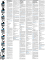 1
1
-
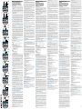 2
2


Shelly 2 Circuit WiFi Relay Switch Mode d'emploi
- Taper
- Mode d'emploi
dans d''autres langues
Documents connexes
-
Shelly WiFi Operated Manuel utilisateur
-
Shelly Plus 1 Mode d'emploi
-
Shelly Plus I4DC Mode d'emploi
-
Shelly DW2 Wi-Fi Door-Window Sensor Mode d'emploi
-
Shelly Pro 4PM Mode d'emploi
-
Shelly Plus Plug S Mode d'emploi
-
Shelly Smart Wi-Fi Humidity and Temperature Sensor Mode d'emploi
-
Shelly Pro 3EM Mode d'emploi
-
-
Shelly D591001B Manuel utilisateur
