
Mon‐
t
age‐
anlei‐
tung
M O N T A G E A N L E I T U N G d e
Alle Rechte vorbehalten. Irrtümer und Änderungen vorbehalten.
1 Zu diesem Dokument
Diese Montageanleitung gilt für das Sicherheitsrelais ReLy OSSD4.
2 Zu Ihrer Sicherheit
GEFAHR
G
efahr der Unwirksamkeit der Schutzeinrichtung
Der Gefahr bringende Zustand der Maschine wird bei Nichtbeachtung mögli‐
cherweise nicht oder nicht rechtzeitig beendet.
b
Beachten Sie den beiliegenden Sicherheitshinweis.
Weitere Informationen zur Arbeit mit der Schutzeinrichtung enthält die Maschi‐
nendok
umentation oder die Betriebsanleitung der Schutzeinrichtung. Sie finden
die EU-Konformitätserklärung und die aktuelle Betriebsanleitung der Schutzein‐
richtung, indem Sie auf www.sick.com im Suchfeld die Artikelnummer eingeben
(Artikelnummer: siehe Typenschildeintrag im Feld „Ident. no.“).
3 Montageablauf
Voraussetzungen
•
Mont
age erfolgt gemäß EN 50274 und Elektroinstallation gemäß
IEC 60204-1 in Schaltschrank mit Schutzart IP54.
•
Montage erfolgt auf 35-mm-Hutschiene (IEC 60715).
•
Hutschiene ist an Funktionserde angeschlossen.
•
Sicherheitsrelais wird vertikal eingebaut (Hutschiene verläuft horizontal).
•
Über und unter dem Sicherheitsrelais ist mindestens 50 mm Platz für die
Luftzirkulation.
•
Vor dem Sicherheitsrelais (Frontseite) ist mindestens 25 mm Platz. Abhängig
von den gewählten Anschlüssen kann auch mehr Platz benötigt werden.
Vorgehensweise
b
S
icherheitsrelais auf Hutschiene stecken.
4 Geräteanschluss
Voraussetzungen
•
K
ontaktabsicherung mit Schmelzsicherung gG oder Leitungsschutzschalter
C: 6 A, maximaler Kurzschlussstrom I ≤ 400 A
•
Der Masseanschluss aller angeschlossenen Geräte hat dasselbe Potential
wie A2.
•
Alle angeschlossenen Geräte und der Rücksetztaster entsprechen der gefor‐
derten Kategorie gemäß ISO 13849-1 und SILCL gemäß IEC 62061 (z. B.
geschirmte Einzelmantelleitungen, getrennte Verlegung).
14
24
34
52
62
I2
A2
44
13
23
33
43
51
61
I1
1
3
5
7
9
11
13
15
2
4
6
8
10
12
14
16
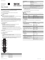
Belegung der Anschlussklemmen
Anschlussklemme Beschreibung
13, 14
1)
2)
Freigabestrompfad
23, 24
1)
2)
Freigabestrompfad
33, 34
1)
2)
Freigabestrompfad
43, 44
1)
2)
Freigabestrompfad
Anschlussklemme Beschreibung
51, 52 Meldestrompfad
61 Rückmeldestrompfad, 24 V DC
62 Rückmeldestrompfad, zum Anschluss an den EDM-Eingang
de
s Basisgeräts
I1 Eingang CH1 (Sicherheitseingang für OSSD 1)
I2 Eingang CH2 (Sicherheitseingang für OSSD 2)
3)
A2 Spannungsversorgung 0 V DC
1)
Die Freigabestrompfade müssen von derselben Spannungsversorgung versorgt werden.
2)
Die Freigabestrompfade und die Schützkontrolle (EDM) müssen innerhalb des Schalt‐
sc
hranks verdrahtet werden.
3)
Bei einkanaligem Basisgerät: Brücke zwischen I1 und I2 anschließen.
5 Statusanzeige (LED)
HINWEIS
SIC
K empfiehlt, die folgende Tabelle auszuschneiden und im Schaltschrank
zu befestigen.
Betriebszustände
LED Status Mögliche Ursache
CH1
O g
rün
Spannung an I1 angelegt
CH2
O g
rün
Spannung an I2 angelegt
6 Datenblatt
Vollständige Übersicht der Technischen Daten: siehe Betriebsanleitung
Be
triebsdaten
ReLy OSSD4
Sicherheitseingänge (I1, I2)
Eingangsspannung HIGH 24 V DC (15 V DC ... 30 V DC)
Schaltspannung für Rückmeldestrompfad 10 V DC ... 30 V DC
10 V A
C ... 30 V AC
Schaltspannung für Freigabestrompfade
In Höhen unter 2000 m ü. NHN 10 V DC ... 250 V DC
10 V A
C ... 250 V AC
In Höhen 2000 m ü. NHN … 4000 m ü.
NHN
10 V DC ... 150 V DC
10 V A
C ... 150 V AC
Schnittstellen
ReLy OSSD4
Anschlussart Zugfederklemme
Leiterquerschnitt
Eindraht (1×) 0,2 mm
2
... 1,5 mm
2
Feindraht (1×) 0,2 mm
2
... 1,5 mm
2
Feindraht mit Aderendhülse mit Kunst‐
s
toffkragen (2×, gleicher Querschnitt)
≤ 0,5 mm
2
Feindraht mit Aderendhülsen mit oder
ohne Kr
agen (1×)
0,25 mm
2
... 1,0 mm
2
Für UL- und CSA-Anwendungen 26 AWG ... 14 AWG
(N
ur Kupferleitung (60/75 °C) verwenden.)
8023916/2019-09-09/de, en, fr ReLy OSSD4 | SICK 1
8023916/2019-09-09
www.sick.com
ReLy OSSD4
SICK AG
E
rwin-Sick
-Straße 1
D-79183 Waldkirch

M O U N T I N G I N S T R U C T I O N S e n
All rights reserved. Subject to change without notice.
1 About this document
These mounting instructions apply for the ReLy OSSD4 safety relay.
2 Safety information
DANGER
Hazard due to lack of effectiveness of the protective device
In the case of non-compliance, it is possible that the dangerous state of the
machine may not be stopped or not stopped in a timely manner.
b
Please observe the safety notes provided.
For more information about how to work with the protective device, refer to the
mac
hinery documentation or the operating instructions for the protective device.
You can call up the EU declaration of conformity and the current operating instruc‐
tions for the protective device by entering the part number in the search field at
www.sick.com (part number: see the type label entry in the “Ident. no.” field).
3 Mounting procedure
Prerequisites
•
Mount
ing is done in accordance with EN 50274 and electrical installation in
accordance with IEC 60204-1 in the control cabinet with enclosure rating
IP54.
•
Mounting is done on a 35 mm mounting rail (IEC 60715).
•
The mounting rail is connected to the functional earth.
•
The safety relay is installed in a vertical orientation (on a horizontal mounting
rail).
•
There is at least 50 mm of space for air circulation above and below the
safety relay.
•
There is at least 25 mm of space in front of the safety relay (front side). More
space may be needed depending on the connections.
Approach
b
A
ttach safety relay to mounting rail.
4 Device connection
Prerequisites
•
C
ontact fuse with safety fuse gG or circuit breaker C: 6 A, maximum short-
circuit current I ≤ 400 A
•
The ground connection of all connected devices must have the same poten‐
tial as A2.
•
All connected devices and the reset pushbutton comply with the required
category in accordance with ISO 13849-1 and SILCL in accordance with IEC
62061 (e.g. shielded single sheathed cables, separate installation).
14
24
34
52
62
I2
A2
44
13
23
33
43
51
61
I1
1
3
5
7
9
11
13
15
2
4
6
8
10
12
14
16
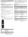
Pin assignment of the terminals
Terminal Description
13, 14
1)
2)
Enabling current path
23, 24
1)
2)
Enabling current path
33, 34
1)
2)
Enabling current path
43, 44
1)
2)
Enabling current path
51, 52 Signaling current path
61 Feedback current path, 24 V DC
62 Feedback current path, for connection to the EDM input of
t
he basic device
I1 CH1 input (safety capable input for OSSD 1)
I2 CH2 input (safety capable input for OSSD 2)
3)
Terminal Description
A2 Voltage supply 0 V DC
1)
The enabling current paths must be supplied by the same voltage supply.
2)
The enabling current path and external device monitoring (EDM) must be wired within the
control cabinet.
3)
With single-channel base device: Connect jumper between I1 and I2.
5 Status indicator (LED)
NOTE
SICK recommends cutting out the table below and attaching it to the wall of
the control cabinet.
Operational statuses
LED Status Possible cause
CH1
O Gr
een
Voltage on I1
CH2
O Gr
een
Voltage on I2
6 Data sheet
See the operating instructions for a full overview of the technical data.
Oper
ating data
ReLy OSSD4
Safety capable inputs (I1, I2)
Input voltage HIGH 24 V DC (15 V DC ... 30 V DC)
Switching voltage for feedback current path 10 V DC ... 30 V DC
10 V A
C ... 30 V AC
Switching voltage for enabling current paths
At altitudes below 2,000 m above sea
le
vel
10 V DC ... 250 V DC
10 V AC ... 250 V AC
At altitudes 2,000 m above sea level …
4,000 m abo
ve sea level
10 V DC ... 150 V DC
10 V AC ... 150 V AC
Interfaces
ReLy OSSD4
Connection type Spring terminal
Wire cross-section
Single wire (1×) 0.2 mm
2
... 1.5 mm
2
Fine wire (1×) 0.2 mm
2
... 1.5 mm
2
Fine wire with ferrule with plastic collar
(2×, s
ame cross-section)
≤ 0.5 mm
2
Fine wire with ferrules with or without collar
(1×)
0.25 mm
2
... 1.0 mm
2
For UL and CSA applications 26 AWG ... 14 AWG
(use onl
y copper wire (60/75 °C))
8023916/2019-09-09/de, en, fr ReLy OSSD4 | SICK 2

N O T I C E D E M O N T A G E f r
Tous droits réservés. Sujet à modification sans préavis.
1 À propos de ce document
Cette notice de montage est valable pour le relais de sécurité ReLy OSSD4.
2 Pour votre sécurité
DANGER
Risque lié au non fonctionnement d’un dispositif de protection
En cas de non-observation de cette consigne, il se peut que la situation dan‐
gereuse de la machine ne s'interrompe pas ou pas à temps.
b
Observer toutes les consignes de sécurité.
La documentation de la machine ou la notice d'instruction du dispositif de protec‐
t
ion contient des informations supplémentaires sur l'utilisation du dispositif de
protection. Pour trouver la déclaration de conformité UE et la notice d'instruction
actuelle du dispositif de protection, taper le numéro d'article dans le champ de
recherche de notre site internet www.sick.com (numéro d'article : voir numéro de
plaque signalétique dans le champ « Ident. no. »).
3 Déroulement du montage
Conditions préalables
•
L
e montage est réalisé selon la norme EN 50274 et installation électrique
selon CEI 60204-1 dans l’armoire électrique avec indice de protection IP54.
•
Montage effectué sur rail DIN 35 mm (CEI 60715).
•
Le rail DIN est raccordé à la terre fonctionnelle.
•
Le relais de sécurité est monté verticalement (rail DIN à l’horizontale).
•
Au-dessus et en-dessous du relais de sécurité, il y a un espace de 50 mm
pour la circulation de l’air.
•
Un espace d’au moins 25 mm existe devant le relais de sécurité (face
avant). Davantage de place peut être nécessaire selon les raccordements
sélectionnés.
Procédé
b
C
onnecter le relais de sécurité au rail DIN.
4 Raccordement de l’appareil
Conditions préalables
•
Pr
otection des contacts gG ou disjoncteur de caractéristique C6A, courant
de court-circuit maximal I ≤ 400 A
•
La connexion à la masse de tous les appareils raccordés doit avoir le même
potentiel qu’A2.
•
Tous les appareils raccordés et le bouton-poussoir de réarmement corres‐
pondent à la catégorie exigée par la norme ISO 13849-1 et à la limite d’exi‐
gence SIL CL selon CEI 62061 (p. ex. des câbles monochemisés blindés,
une pose isolée).
14
24
34
52
62
I2
A2
44
13
23
33
43
51
61
I1
1
3
5
7
9
11
13
15
2
4
6
8
10
12
14
16
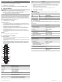
Affectation des broches
Borne Description
13, 14
1)
2)
Canal de commande sûr
23, 24
1)
2)
Canal de commande sûr
33, 34
1)
2)
Canal de commande sûr
43, 44
1)
2)
Canal de commande sûr
51, 52 Canal de signalisation
61 Circuit de courant de retour 24 V CC
62 Circuit de courant de retour, pour le raccordement à l’entrée
EDM de l’appar
eil de base
I1 Entrée CH1 (entrée de sécurité pour OSSD 1)
I2 Entrée CH2 (entrée de sécurité pour OSSD 2)
3)
Borne Description
A2 Alimentation électrique 0 V CC
1)
Les canaux de commande sûrs doivent être alimentés par la même alimentation élec‐
trique.
2)
Les canaux de commande sûrs et le contrôle des contacteurs commandés (EDM)
doivent être câblés dans l’armoire électrique.
3)
Avec appareil de base mono canal : raccorder le fil jarretière entre I1 et I2 :
5 Affichage d’état (LED)
REMARQUE
SICK recommande de découper le tableau suivant et de l’accrocher dans
l’armoire électrique.
États de fonctionnement
LED État Cause possible
CH1
O v
ert
Tension appliquée sur I1
CH2
O v
ert
Tension appliquée sur I2
6 Fiche technique
Pour une vue d'ensemble complète des données techniques : cf. notice d’instruc‐
t
ion.
Données fonct.
ReLy OSSD4
Entrées de sécurité (I1, I2)
Tension d’entrée HIGH 24 V CC (15 V CC ... 30 V CC)
Tension de commutation pour circuits de cou‐
r
ant de retour
10 V CC ... 30 V CC
10 V CA ... 30 V CA
Tension de commutation pour canaux de commande sûrs
Altitudes inférieures à 2.000 m au-dessus
du ni
veau de la mer
10 V CC à 250 V CC
10 V CA à 250 V CA
Altitudes entre 2.000 m et 4.000 m au-
de
ssus du niveau de la mer
10 V CC ... 150 V CC
10 V CA ... 150 V CA
Interfaces
ReLy OSSD4
Mode de raccordement Borne à ressort
Section du conducteur
Monobrin (1×) 0,2 mm
2
... 1,5 mm
2
Fil de faible diamètre (1×) 0,2 mm
2
... 1,5 mm
2
Fil de faible diamètre avec conducteurs
manc
honnés dotés de collerettes en plas‐
tique (2×, section identique)
≤ 0,5 mm
2
Fil de faible diamètre avec conducteurs
manchonnés, a
vec ou sans collerette (1x)
0,25 mm
2
... 1,0 mm
2
Pour les applications UL et CSA 26 AWG ... 14 AWG
(ut
iliser uniquement un conducteur en cuivre
(60/75 °C))
8023916/2019-09-09/de, en, fr ReLy OSSD4 | SICK 3

8023916/2019-09-09/de, en, fr ReLy OSSD4 | SICK 4
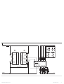
A
3) PELV
F2 F1F4 F3
+24 V DC
0 V DC
E243849/00/2019-06-14
System connection
System connection
+24 V DC
deTec4 SP1
2
1
3
5
6
4
7
8
r
RES
ADO
OSSD1
OSSD2
EDM
0 V DC
Com1
s
+24 V DC
n.c
In2
In1
n.c
.
0 V DC
Com1
n.c.
2
3
4
5
6
1
7
8
2)
F0
L+
L–
1)
k2k1
x1
x1
y1
y1
k4k3
x2
x2
y2
y2
k4
k3
z2
z2
k2
k1
z1
z1
K4 K3 K2 K1
344
432A2 24
I1 I2 334331 23
14
13
RLY3-OSSD4
-
 1
1
-
 2
2
-
 3
3
-
 4
4


SICK ReLy OSSD1 Mounting instructions
- Taper
- Mounting instructions
- Ce manuel convient également à
dans d''autres langues
- English: SICK ReLy OSSD1
- Deutsch: SICK ReLy OSSD1
Documents connexes
-
SICK ReLy OSSD1 Mounting instructions
-
-
-
-
-
-
-
-
-