La page charge ...

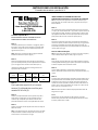
#1 Snap Latch
AUTO-LATCH LOCK ASSEMBLY
INSTRUCTIONS
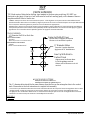
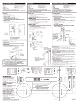
Step 1
Using the template provided on page 6, drill three
holes through the garage door. The template should
be placed at a location nearest the center of the door
on the second section. (FIG. 1)
NOTE: To assure easy installation the holes must be
drilled straight. (Not at an angle.)
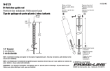
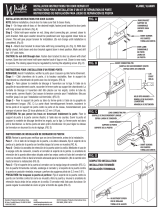
Step 2
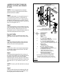
Slide the rubber gasket (8) over the outside handle
(1), then insert the outside handle and the two lock
spacers (7)* into the holes in the lock section. (FIG.
2)
*Please refer to table below for lock spacer
configuration.
Door
Style
Uninsulated
1 3/8”
Insulated
2”
Insulated
2” Pinch
Resistant
Spacer 2” Plastic
1-3/8”
Plastic
None
1-7/8”
Plastic
Step 3
Attach the backing plate (2) to the outside handle (1)
using two #10 x 24 machine screws (3).
Step 4
Slide the inside release handle (4) over the shaft of
the outside handle and secure in place using the
Tinnerman nut (5). Be sure the Tinnerman nut is
pressed firmly against the inside release handle.
Step 5
Slide the vinyl sleeve (6) over the arm of the inside
release handle.
Note: The Spring Latches, Striker Plates and Lock
Cables are to be assembled after the door and all
other hardware are in place.
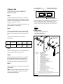
Center Width of Door
Template Placement (See Fig 4)
Note: Panel configuration may differ depending on the width of the door.
If door has an odd number of panels lock to be installed off center.
FIGURE 1
Center of Door in Height
Remarque:Laconfigurationdupanneaupeutdifférerselonlalargeurdelaporte.
Silaportecomporteunnombreimpairdepanneaux,leverrouseradécentré.
Centredelalargeurdelaporte
Emplacementdugabarit(voirfig4)
Centredelahauteurdelaporte
Centrodelapuertacon
respectoalancho
Colocacióndelaplantilla(Refiéraseala
figura4).
FIGURA 1
#1 Snap Latch
Fermetureàenclenchementn°1
CerraduraapresiónNº1
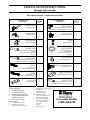
NO.
QTY DESCRIPTION
11
21
41
Key blanks are available through Clopay.
Rubber Gasket
Vinyl Sleeve
Tinnerman Nut
Inside Release Handle
#10-24 Machine Screws
Backing Plate
Outside “T” Handle
½” DIA (TYP)
FIGURE 2
FIGURA 2
½ poDIA(TYP)
½”DIÁM .(TIP )
QUANTITÉ
DESCRIPTION
Nº
CANT.
N°
DESCRIPCIÓN
Poignéeextérieureen« T»
Manijaexternaen“T”
Plaqued'appui
Placadesujeció n
32
Visà métauxn°10‐24
T o rn illo s parametalesNº10‐24
Poignéeded év e r r o uilla g eintérieu re
Manijadeli b e r a c i ó n interior
51
ÉcrouTinnerman
TuercaTinnerman
61
Manchonenvinyle
Manguitodev inilo
72
Spacer Tubes (As Needed)
Tubesespaceurs(au besoin)
Tubosespaciadores(s egú nse anecesario)
81
Tampondecaoutchouc
Empaquetaduradegom a
Ilestpo s s ible deseprocurerdesclésbrutesauprèsdeClopay.
Clopaytien edisponiblesllav e s enbruto.
La page charge ...

INSTRUCTIONSD’INSTALLATION
Assemblagedefermetureàenclenchementn°1
Fermetureàenclenchementn°1
INSTRUCTIONSD’ASSEMBLAGEDEVERROUÀ
LOQUETAUTOMATIQUE
Étape1
Àl’aidedugabaritfourniàlapage6,perceztroistrousdansla
portedegarage.Legabaritdevraitêtreplacéleplusprèspossible
ducentredelaporte,surladeuxièmesection.(FIG.1)
REMARQUE:Pourfaciliterl’installation,percezles
trousdroits(pasdansunangle.)
Étape2
Glissezletamponencaoutchouc(8)surlapoignéeextérieur e(1),
puisinsérezcelle‐cietlesdeuxespaceurs(7)*deverroudansles
trous,danslasectionduverrou.(FIG.2)
*Veuillezvousreporterautableauci‐aprèsillustrantla
configurationdesespaceurs.
Typede
porte
Non
isolée
13/8po
non
isolée
2po
isolée
2poanti‐
pincement
Espaceurs
2poen
plastique
13/8en
en
plastique
Aucun
17/8po
en
plastique
Étape3
Fixezlaplaqued’appui(2)àlapoignéeextérieure(1)àl’aidedes
deuxvisàmétauxn°10x24(3).
Étape4
Glissezlapoignéededéverrouillageintérieure(4)surlatigede
poignéeextérieureetfixezenplaceàl'aidedel'écrouTinnerman
(5).Assurez‐vousquel’écrouTinnermanestsolidementappuyé
contrelapoignéededéverrouillageintérieure.
Étape5
Glissezlemanchonenvinyle(6)surl’axedelapoignéede
déverrouillageintérieure.
Remarque:Lesloquetsàressort,lesgâchesetlescâblesde
verrouillagedoiventêtreassemblésaprèsquelaporteettoute
autrepiècedequincaillerieontétéposées.
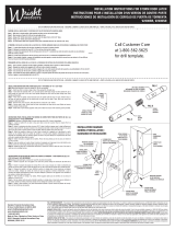
INSTRUCTIONSD’ASSEMBLAGEPOURLESLOQUETSÀ
RESSORTETLESGÂCHES
REMARQUE:Silaporteestéquipéed’unouvre‐porteautomatiquede
garage,lesloquetsàressortetlesgâchesnedevraientpasêtre
installés.
Étape1
Fixezlagâche(1)auraildeguidageàl’aidededeuxboulonsde¼pox
5/8po(2)deraildeguidageetdedeuxécrousàbridede¼po(3).
Insérezlesboulonsdanslesdeuxtrousde9/32posituésdansles
partiessupérieureetinférieure
dugranddécochage.REMARQUE:
Assurez‐vousquelagâches’enrouleautourdel’arrièredurailde
guidage,telqu’illustré.Neserrezpas(FIG.3)
Étape2
Placezleloquetàressort(4)surlemontantd’extrémitédelasectionde
porteetalignezleloquetàressortaveclagâcheetlestrousdu
montant.Fixezàl’aidededeuxvisautotaraudeusesn°1x5/8po(5).
Assurez‐vousquelagâches’enrouleautourduloquet
àressortetest
fixéeenplace.
Pourlescâblesdeverrouillage
REMARQUE:Sileverrouestsituéaucentredelalargeurdelaporte,
coupezlecâbledeverrouillage(6)àmoitiéetpassezàl’étape3.
Étape1
Faitestournerlapoignéededéverrouillageintérieuredanslesensdes
aiguillesd’unemontrejusqu’àcequ’elles’arrête.Mesurezdepuisle
trousupérieurgauchedelapoignéeàl’extrémitéduloquetàressort
gauche
.
Étape2
Saisissezlecâbledeverrouillage(6)etenutilisantlamesureobtenue,
mesurezdepuisl’intérieurdelabutéedecâble(7)etcoupezlecâble.
Étape3
Enfilezlecâbledansletrougauchedelapartiesupérieuredela
poignéededéverrouillageintérieure,deparen‐dessous,jusqu’àceque
leboutond’arrêtcontactelapoignée.Tendezlecâblejusqu’auloquetà
ressortgaucheetfaitespasserl'extrémitéducâbledansletrou,tel
qu'illustré,puisfixez
‐leenplaceavecunboulonde¼pox5/8po(2)de
raildeguidageetunécroude¼po(3).
REMARQUE:Assurez‐vousdetendrelecâbleavantdelefixerenplace.
Étape4
Répétezlaprocédurepourl’autrecôtéenutilisantlecâblerestantetle
troudroitsurlapartieinférieuredelapoignée.Certainesportesà
ressortdetorsionpeuventn’avoirqu’unseulcâble.
Assistance téléphonique à la
clientèle
1-800-225-6729
La page charge ...

© 2011 CBPC P/N 0130288 REV00
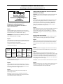
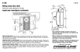
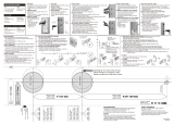
TOP
TOOLS NEEDED:
-Drill
- ½” Diameter Drill Bit or Hole Saw
The ½” diameter holes should be the same distance from the floor as the rectangular slots in the vertical
track. Please refer to the lock instructions to complete lock assembly.
FIGURE 4
FIGURA 4
HAUT
PARTESUPERIOR
TIP: Mark center of holes before drilling: tape template to the door using scotch tap (DO NOT use
electrical or duct tape). Align tip of nail with center of each hole and tap gently with a hammer. Remove
template and drill holes to correct size.
CONSEIL:Marquezlecentredestrousavantdelespercer:collezlegabaritsurlaporteavecdurubanadhésifScotch
(N'utilisezPASderubanisolantouàconduits).Alignezlapointeduclouaveclecentredechaquetrouettapezdélicatement
avecunmarteau.Enlevezlegabaritet
percezlestrousauxdimensionsappropriées.
CONSEJOÚTIL:marqueelcentrodelosagujerosantesdetaladrar:peguelaplantillaalapuertautilizandocintaadhesiva
transparente(NOutilicecintaaislantenicintaplateada).Alineelapuntadelclavoconelcentrodecadaagujeroygolpee
ligeramenteconunmartillo.Retire
laplantillayperforelosagujerosaltamañoadecuado.
OUTILSNÉCESSAIRES:
HERRAMIENTASNECESARIAS:
‐Perceuse
‐Taladro
‐Mèchedeperceuseouscie‐clochede½po
‐Brocaosierracilíndricade½”
#1 LOCK HOLE PATTERN
MODÈLEDETROUDEVERROUN°1
PATRÓNDEAGUJERODECERRADURANº1
Lestrousde½podediamètredevraientêtresituésàlamêmedistancedusolquelesfentesrectangulairesdanslerailde
guidagevertical.Veuillezvousreporterauxinstructionsrelativesauverroupourterminerl'assemblagede
celui‐ci.
Losagujerosde½”dediámetrodebenestaralamismadistanciadelpisoquelasranurasrectangularesdelrielvertical.
Refiérasealasinstruccionesparaterminarelensamblajedelacerradura.
3/4"
3/4"
Center In Width Of Door
½” Diameter Holes
Line Up With Slots In
Vertical Track
Centredanslalargeurdelaporte
Trousde½podediamètre
Alignezaveclesfentesdans
leraildeguidagevertical
Alineeconlasranurasenelriel
vertical
Agujerosde½”dediámetro
Centreenelanchodelapuerta
-
 1
1
-
 2
2
-
 3
3
-
 4
4
-
 5
5
-
 6
6


dans d''autres langues
Autres documents
-
 Prime-Line N 6729 Guide d'installation
-
 Prime-Line A 120 Guide d'installation
-
Onward 67FSBCR Mode d'emploi
-
-
 Faultless MYEX2L1B-F Mode d'emploi
-
 Wright Products VLANBZ Mode d'emploi
-
 Wright Products V2200SN Mode d'emploi
-
RDI 73014244 Mode d'emploi
-
Kwikset 801TVH LIP 26 SMT 6AL RCS Mode d'emploi
-
 Faultless HY7731B-F Manuel utilisateur


