Acson IM-FCU-0501-ACSON Guide d'installation
- Catégorie
- Climatiseurs split-system
- Taper
- Guide d'installation

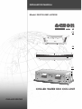
CHILLED WATER FAN COIL UNIT
Model: IM-FCU-0501-ACSON
CHILLED WATER
INSTALLATION MANUAL
CC
CE
CK


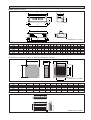
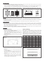
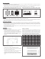
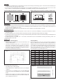
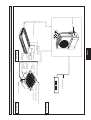
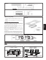
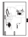
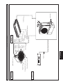
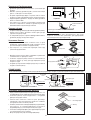
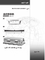
OUTLINE AND DIMENSIONS
Indoor Unit (CC Series)
G
A
R
E
N
OM
S
D
QP
L
H
I
U
F
D
C
CK
B
J
T
Indoor Unit (CK Series)
(With Wireless Remote Control & With Wired Remote Control)
All dimensions are in mm.
All dimensions are in mm.
F
H
I
J
G
K
E
C
D
B
A
i
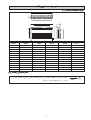
CC Model A B C D E F G H I J K L M N O P Q R S T U
10BW 700 240 25 780 30 50 754 410 350 182 193 140 565 25 90 45 30 673 653 255 190
15BW 800 240 25 880 30 50 854 410 350 182 193 140 665 25 90 45 30 773 753 255 190
20BW 1000 240 25 1080 30 50 1054 410 350 182 193 140 865 25 90 45 30 973 953 255 190
25BW 1200 240 25 1280 30 50 1254 410 350 182 193 140 1065 25 90 45 30 1173 1153 255 190
30BW 1500 240 25 1580 30 50 1554 410 350 182 193 140 1345 25 90 45 30 1473 1453 255 190
40BW 1800 240 25 1880 30 50 1854 410 350 182 193 140 1665 25 90 45 30 1773 1753 255 190
CK Model A B C D E F G H I J K
20AW 820 820 363 335 28 930 930 642 622 555 555
25AW 820 820 363 335 28 930 930 642 622 555 555
30AW 820 820 363 335 28 930 930 642 622 555 555
40AW 820 820 363 335 28 930 930 642 622 555 555
50AW 820 820 363 335 28 930 930 642 622 555 555
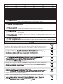
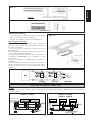
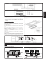
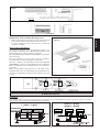
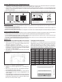
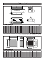
Indoor Unit (CE Series)
A
B
C
G
L
F
E
M
I
H
H
KJ
D
All dimensions are in mm.

NOTICE
! Caution
Sharp edges and coil surfaces are potential locations which may cause injury
hazards. Avoid from being in contact with these places.
CE Model 20DW 25DW 30DW 40DW 50DW
A 1174 1174 1174 1674 1674
B 75 75 75 75 75
C 1082 1082 1082 1582 1582
D 68 68 68 68 68
E 58 58 93 93 93
F 156 156 156 156 156
G 1214 1214 1214 1714 1714
H 57 57 57 57 57
I 670 670 670 670 670
J 216 216 216 216 216
K 319 319 319 319 319
L 879 879 879 1379 1379
M 517 517 517 517 517
ii
! Avertissement
Les bords coupants et les surfaces du refroidisseur tubulaire présentent
un risque de blessure. Mieux vaut éviter le contact avec ces endroits.
! Vorsicht
Scharfe Kanten und Wärmetauscherflächen stellen eine Gefahrenquelle dar.
Jeglicher Kontakt mit diesen Stellen ist zu vermeiden.
! Cautela
Per preservarsi da eventuali ferite, evitare di toccare gli spigoli affilati e la superficie
dei serpentini.
! Cuidado
Los Bordes afilados y la superficie del serpentín pueden producir lesiones. Evite
tocarlos.
! Осторожно
Острые края и поверхности змеевиков являются потенциальными
местами нанесения травм. Остерегайтесь контакта с этими местами.
This product is subjected to Waste of Electrical and Electronic Equipment Regulations (WEE
E
Regulations). The waste product shall be separately collected by specific collection and treatment centre
.
P
lease refer to local authorithy for these centres. This is only applicable to European Union countries
.
Ce produit est soumis
à
la r
à
é
rr
é
é
é
lectriques e
t
é
é
é
ê
é
é
é
é
é
é
é
é
é
î
î
tre ces centres. Ceci
îî
est uniquement applicable aux pays de l'Union Euro
p
é
enne
.
Questo prodotto
è
soggetto alle disposizioni RAEE (Rifiuti di apparecchiature elettriche ed elettroniche)
.
à
à
locali. Questa disposizione
à
è
valida solamente i paes
i
d
el
l
’
U.
E
.
é
ctrico y Electr
ó
n
ico en materia d
e
ñ
ñ
á
í
fico
í
í
de colecc
i
ó
solamente aplicable a los p
a
í
ses de la
U
n
i
ó
n
Europea
.
Dieses Produkt unterliegt den Bestimmungen zur Entsorgung von elektrischen und elektronische
n
G
er
ä
ä
ä
tes
ää
ü
ü
ll bei Ihrer
ö
ü
ö
ä
ndiges Abfall-Amt. Dieser
ää
Hinweis gilt nur f
ü
f
f
rL
ä
ischen Union
.
П
р
оцес
с
у
тилизаци
и
д
анног
о
прод
у
кт
а
рег
у
лир
у
етс
я
п
р
авилам
и
п
о
у
тилизаци
и
отхо
д
о
в
и
(WEEE Re
g
ulations).
и
,
.
Э
т
и
п
р
авил
а
Ев
р
опейског
о
.

1-1
English
This manual provides the procedures of installation to ensure a safe and good standard of operation for the air
conditioner unit.
Special adjustment may be necessary to suit local requirements.
Before using your air conditioner, please read this instruction manual carefully and keep it for future reference.
INSTALLATION MANUAL
CHILLED WATER FAN COIL UNIT
MODEL
CK
Reference Model
CK20AW
CK25AW
CK30AW
CK40AW
CK50AW
CE
Reference Model
CE20DW
CE25DW
CE30DW
CE40DW
CC
Reference Model
CC10BW
CC15BW
CC20BW
CC25BW
CC30BW
CC40BW
Part No.:A08019025522
IM-FCU-0501(1)-Acson
Model
ACK020AW
ACK025AW
ACK030AW
ACK040AW
ACK050AW
Model
ACM020DW
ACM025DW
ACM030DW
ACM040DW
Model
ACC010BW
ACC015BW
ACC020BW
ACC025BW
ACC030BW
ACC040BW

1-2
CONTENTS
- Outline And Dimensions (CC series) page 0 i
- Outline And Dimensions (CK series) page 0 i
- Outline And Dimensions (CE series) page 0ii
- Safety Precautions page 02
- Installation Diagram page 03
- Installation Of Indoor Unit page 04
- Electrical Wiring Connection page 7
- Overall Checking page 8
- Service And Maintenance page 8
- Trouble Shooting page 8
SAFETY PRECAUTIONS
Before installing the air conditioner unit, please read the following safety precautions carefully.
! Caution
Please take note on the following important points when installing.
• Do not install the unit where leakage of flammable gas may occur.
If water gas leaks and accumulates at the surrounding of the unit, it may cause fire ignition.
• Ensure that the drainage piping is connected properly.
If the drainage piping is not connected properly, it may cause water leakage which will dampen the
furniture.
• Ensure that the unit panel is covered back after service or installation.
Unsecured panel will cause the unit to operate noisily.
! Warning
• Installation and maintenance should be performed by qualified persons who are familiar with local code and
regulation, and experienced with this type of appliance.
• All field wiring must be installed in accordance with the national wiring regulation.
• Ensure that the rated voltage of the unit corresponds to that of the name plate before commencing wiring work
according to the wiring diagram.
• The unit must be GROUNDED to prevent possible hazard due to insulation failure.
• All electrical wiring must not touch the refrigerant piping or any moving parts of the fan motors.
• Confirm that the unit has been switched OFF before installing or servicing the unit.
IMPORTANT
DO NOT INSTALL OR USE THE AIR CONDITIONER UNIT IN A LAUNDRY ROOM.

1-3
English
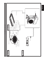
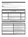
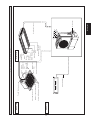
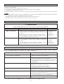
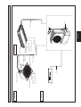
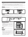
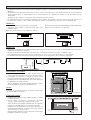
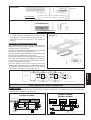
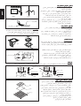
INSTALLATION DIAGRAM
CE Model
CK Model
Drain Hose
Front Panel
Air Discharge
Louver
Air Intake
Grille
IR Receiver
LED Light
Air
Discharge
Louver
Signal
Receiver
Indicator
Lights
Air Filters
(Inside Air Intake Grille)
Air Filter
(Behind The Grille)
Water Piping
Chiller
Water Piping
CC Model
Water Piping
Air Intake Grille
Air Discharge Grille
Air Discharge Louver

1-4
• Electrical supply and installation is to conform to local authority's (e.g. National Electrical Board) codes and regulations.
• Voltage supply fluctuation must not exceed ±10% of rated voltage. Electricity supply lines must be independent of welding
transformers which can cause high supply fluctuation.
• Ensure that the location is convenient for wiring, piping and drainage.
• The indoor unit must be installed in such a way that is free from any obstacles in the path of cool air discharge and warm air
return, and must allow spreading of air throughout the room (near the center of the room).
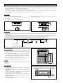
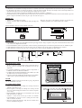
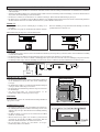
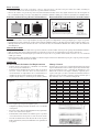
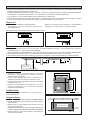
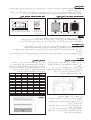
CC Model
• Use the hanger supplied with the unit.
• Make sure that the wall is sufficiently strong to withstand
the weight.
Provide clearance for servicing ease and optimal air flow as
shown in the diagram.
INSTALLATION OF INDOOR UNIT
10 mm
10 mm
140 mm
CK Model
• The installation place must be strong enough to support a load 4 times weight of the indoor unit to avoid noise amplification
and vibration.
• The installation place (handing ceiling surface) must be assuring levelness and the height in the ceiling is 350mm or more.
• The indoor unit must be placed away from heat and steam sources (avoid installing it near an entrance).
• Must be provide clearance for the indoor unit from the wall and obstacles as shown in the figure.
Max. 0.3 m
Min. 0.5 m
Min. 0.5 m
Min. 0.5 m
Min. 1.0 m
Max. 3.0 m
Obstacle
Beam
Floor
Center distance of axle (see drawing below)
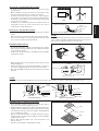
Unit Installation
• Measure and mark the position for the hanging rod. Drill
the hole for the angle nut on the ceiling and fix the hanging
rod.
• The installation template is extended according to
temperature and humidity. Check on dimensions in use.
• The dimensions of the installation template are the same as
those of the ceiling opening dimensions.
• Before ceiling laminating work is not completed, be sure
to fit the installation template to the indoor unit.
NOTE:
Be sure to discuss the ceiling drilling work with the installers
concerned.
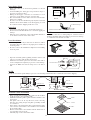
Piping Direction
Unit Hanging
• Confirm that the pitch of the hanging rod is 790mm x
620.5mm sharp.
• Hold the unit and hang it on the hanging rod with the nut
and washer.
• Adjust the unit height to 35.0mm between the indoor unit
bottom surface and the ceiling surface.
• Confirm with a level gauge that the unit is installed hori-
zontally and tighten the nut and bolt to prevent unit from
falling and vibrating.
• Open the ceiling board along the outer edge of the paper
installation template.

1-5
English
Indoor Unit
Pipe Clamp
Good
Bad
NOTE:
This indoor unit uses a drain pump for condensed water
drainage. Install the unit horizontally to prevent water leakage
or condensation around the air outlet.
Drain Piping Work
• Drain pipe must be in downward gradient for smooth
drainage.
• Avoid installing the drain pipe in up and down slope to
prevent reversed water flow.
• During the drain pipe connection, be careful not to exert
extra force on the drain connector at indoor unit.
• The outside diameter of the drain connection at the flexible
drain hose is 20mm.
• Be sure to execute heat insulation (polyethylene foam with
thickness more than 8.0mm) on the drain piping to avoid
the condensed water dripping inside the room.
Drain Test
• Connect the main drain pipe to the flexible drain hose.
• Feed water from flexible drain hose to check the piping for
leakage.
• When the test is completed, connect the flexible drain hose
to the drain connector on the indoor unit.
Panel Installation
• The front panel can only be fitted in one direction, follow
the piping direction. (Observe the piping arrow sticker on
the front panel).
• Be sure to remove the installation template before installing
the front panel.
• Open the air intake grille by pulling back the catchers and
remove it together with the filter from panel.
• Install the front frame panel onto the indoor unit with 4
screws and tighten it completely to prevent cool air leakage.
• Connect the LED wire and air swing wire to the indoor
unit.
From Front Panel
LED Wire
Air Swing
Wire
Control Box
NOTE:
Install the front frame panel firmly to prevent cool air leakage which will cause condensation and water dripping.
Air leak
Cool Air
Indoor Unit
Cool Air
Ceiling Board
Panel
Air leak
Ceiling Board
Panel
Good Installation Bad Installation
Open
Screws
Main Drain Pipe
Feed Water
Flexible Drain Hose
Air Intake Grille Installation
• Before installed the air intake grille, make sure the air filter
is clip properly to the air intake grille.
• Install the air intake grille together with the air filter to the
front panel.
• The grille can be fit in any direction, when selecting
direction, the ceiling design and grille operability should
be considered.
• If the unit is come with ionizer filter (optional item), make
sure to fix the ionizer filter to the air filter before installed
the air intake grille.
• Fix the ionizer filter to the air filter with the black side on
top and white side at bottom.
• Carefully clip on the ionizer filter frame.
Frame
Ionizer
Filter

1-6
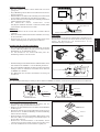
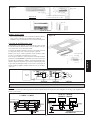
Accessory Part
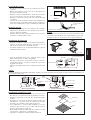
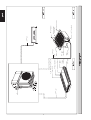
• The indoor unit is provided with air discharge and air intake “knock-out” hole for duct connection. However the connection
of the short duct for air discharge is possible on only one side.
• The use of short duct for air discharge will improve airflow distribution if there is an obstruction (such as a lighting fixture)
or in a long, narrow room or an L-shaped room. It also use for air conditioning of two rooms simultaneously.
Possible Direction For Air Discharge And Air Intake Possible Opening Dimension For Duct Connection
Air Intake
Air Discharge
Air Discharge
Air Discharge
Air Discharge
10
50 50 50 50 50 10
207020109
119 90
Ø100
PCD Ø140
115 20 115
Air Discharge Knock Out Hole Air Intake Knock
Out Hole
NOTE:
• Avoid using the short duct on which the air discharge grille can be completely closed, to prevent evaporator freezing.
• In order to prevent condensation forming, be sure that there is sufficient thermal insulation and no leakage of cool air when
installing the short duct.
• Keep the introduction of fresh air intake within 20% of total air flow. Also provide a chamber and use a booster fan.
Sealing Material
• It is possible to seal one of the four air discharge outlet. (sealing two or more air discharge outlet could cause a malfunction)
• Remove the front panel and insert the sealing material into the air discharge outlet on the indoor unit to seal the air outlet.
• The sealing material is the same length as the longer air discharge outlet. If it is desired to seal the shorter air discharge
outlet, cut the sealing material to shorten it.
• Push the sealing material in about 10mm beyond the bottom surface of the indoor unit so that it does not touch the air louver.
Be sure not to push the sealing material in any farther than about 10mm.
Figure A
CE Model
Preliminary Site Survey
• Electrical supply and installation shall conform to the local
authority (e.g. National Electrical Board).
• Voltage supply fluctuation must not exceed ±10% of the
rated voltage. Electricity supply lines must be
independent of welding transformers which can cause high
supply fluctuation.
• Ensure that the installation location is convenient for wiring
and piping.
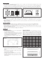
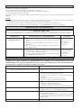
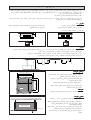
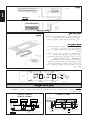
Standard Mounting
Ensure that the overhead supports are strong enough to hold
the weight of the unit. Position the hanger rods (wall
mounting bracket for floor standing), and check for its
alignment with the unit as shown in Figure A. Also, check
that the hangers are secured and the base of the fan coil unit is
leveled in both horizontal directions, taking into account
the
gradient for drainage flow as recommended in Figure B.
Model 20 25 30 40 50
A 1214 1214 1214 1714 1714
B 666 666 666 666 666
C 273 273 273 273 273
D 130 130 130 130 130
E 1160 1160 1160 1560 1560
F 27 27 27 27 27
G 77 77 77 77 77
H 745 745 745 1235 1235
I 25 25 25 25 25
J 209 209 209 331 331
K 486 486 486 486 486
L 108 108 108 108 108
M 360 360 360 600 600
Figure B
Please ensure that the following steps are taken:
• Check the gradient for drainage flow as recommended in
Figure B.
• Provide clearance for easy servicing and optimal air flow
as shown in Figure C.
• The indoor unit must be installed such that there is no
short circuit of the cool discharge air with the warm
return air.
• Do not install the indoor unit where there is direct
sunlight shining on the unit. The location should be
suitable for piping and drainage installation. The unit must
be a large distance away from the door.
10.0mm
10.0mm Lower

1-7
English
Ceiling Type
Figure C
Floor Standing Type
Utensils, furnitures or built-in architectural
features must not protrude more than 250.0mm
Semi-Enclose Mounting
• In case the unit is to be half-recessed into a false ceiling,
please check that the unit is well-aligned.
• Provide the installation space as shown in Figure D.
Figure D
Water Piping Connection
The indoor unit is equipped with water outlet and inlet bare
connection. There is an air-vent for air purging that is fitted at
the outlet water header.
3 ways solenoid valve is required for cycling off or bypass
the chilled water.
Black steel pipe, polyethrene pipe, PVC pipe and copper tube
are recommended in field installation.
All types of piping and connection must be insulated by
polyurethane (ARMAFLEX type or equivalent) to avoid
condensation.
Do not use contaminated or damaged pipe and fitting for
installation.
Some main fitting components are needed in the system to
enhance the capacity and ease of service, such as gate valve,
balancing valve, 2 ways or 3 ways solenoid valve, filter,
strainer etc.
Ceiling Board Top Panel Of Unit
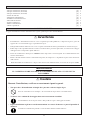
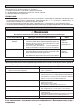
ELECTRICAL WIRING CONNECTION
NOTE:
This is a proposed wiring connection. It may change subject to the chiller unit and must comply with the local and national
code and regulations.
FL FM FH SH TH L N
FL FM FH SH TH L N
FL FM FH SH TH L N
FCU 1 FCU 2 FCU 3
TH
3wv
x1
TH
3wv
TH
3wv
R
S
T
N
x2
x3
3wv
TH
CC10BW~CC40BW
CK20AW~CK50AW
CE20DW~CE40DW
COMP L N
FCU 1
3wv
COMP L N
FCU 2
COMP L N
FCU 3
3wv
x1
3wv
x2
3wv
x3
R
S
T
N

1-8
When any malfunction of the air conditioner unit is noted, immediately switch off the power supply to the
unit. Check the following fault conditions and causes for some simple trouble shooting tips.
TROUBLE SHOOTING
Causes / Action
- Protection against frequent starting. Wait for 3 to 4
minutes for the compressor to start operating.
- Power failure, or the fuse need to be replaced.
- The power plug is disconnected.
- It is possible that your delay timer has been set incorrectly.
- If the fault persist after all these verifications, please
contact the air conditioner unit installer.
- The air filter is dirty.
- The doors or windows are open.
- The air suction and discharge are clogged.
- The regulated temperature is not high enough.
- Odors may be caused by cigarettes, smoke particles,
perfume etc. which might have adhered onto the coil.
- This is caused by air humidity after an extended long
period of operation.
- The set temperature is too low, increase the temperature
setting and operate the unit at high fan speed.
- Switch off unit and call dealer.
Fault
1. The compressor does not start operate after 3 minutes
from starting the air conditioner unit.
2. The air conditioner unit does not operate.
3. The air flow is too low.
4. Discharge air flow has bad odor.
5. Condensation on the front air grille of the indoor unit.
6. Water flowing out from the air conditioner unit.
If the fault persists, please call your local dealer / serviceman.
SERVICE AND MAINTENANCE
! Warning
Disconnect from the main supply before servicing the air conditioner unit.
Maintenance Procedures
1. Remove any dust adhere on the filter by using a vacuum cleaner
or wash in lukewarm water (below 40°C) with neutral cleaning
detergent.
2. Rinse the filter well and dry before placing it back onto the unit.
3. Do not use gasoline, volatile substances or chemical to clean
the filter.
1. Clean any dirt or dust on the grille or panel by wiping it off
with soft cloth soaked in lukewarm water (below 40°C) with
neutral detergent solution.
2. Do not use gasoline, volatile substances or chemical to clean
the indoor unit.
Period
At least once every
2 weeks.
More frequently if
necessary.
At least once
every 2 weeks.
More frequently if
necessary.
Service Parts
Indoor Air Filter
Indoor Unit
Ensure the following, in particular:-
1) The unit is mounted solidly and rigid in position.
2) Piping and connections are leak proof after charging.
3) Proper wiring has been done.
Drainage check - pour some water into left side of drain pan (drainage is at the right side of the unit).
NOTE:
• The installation guide above covers only the fan coil unit. For installation of outdoor (chiller mini chiller etc) please refer to
the installation guide for such unit.
• The installation of fan coil unit may vary according to the type of outdoor unit.
• Installation must be done by qualified personnel who are familiar with this type of product.
OVERALL CHECKING

2-1
Français
Ce manuel fournit les procédures d’installation pour assurer le bon fonctionnement et la sécurité de cet appareil.
Des ajustements peuvent être nécéssaires pour suivre les réglementations locales.
Avant d’installer et de faire fonctionner le climatiseur, lisez attentivement ce manuel et conservez le.
MANUEL D'INSTALLATION
REFROIDISSEUR A SERPENTIN
MODÉLE
Modèle
ACK020AW
ACK025AW
ACK030AW
ACK040AW
ACK050AW
Modèle
ACM020DW
ACM025DW
ACM030DW
ACM040DW
Modèle
ACC010BW
ACC015BW
ACC020BW
ACC025BW
ACC030BW
ACC040BW
CK
Modèle De Référence
CK20AW
CK25AW
CK30AW
CK40AW
CK50AW
CE
Modèle De Référence
CE20DW
CE25DW
CE30DW
CE40DW
CC
Modèle De Référence
CC10BW
CC15BW
CC20BW
CC25BW
CC30BW
CC40BW
Part No.:A08019025522
IM-FCU-0501(1)-Acson

2-2
SOMMAIRE
- Dimensions (Series CC) page 0 i
- Dimensions (Series CK) page 0 i
- Dimensions (Series CE) page 0ii
- Précautions de sécurité page 02
- Diagramme d’installation page 03
- Installation del l’unité intérieure page 04
- Raccordement électrique page 7
- Vérification générale page 8
- Entretien et maintenance page 8
- Analyse des causes de dysfonctionnement du climatiseur page 8
PRÉCAUTIONS DE SÉCURITÉ
Avant de faire fonctionner l'appreil, veuillez bien lire les précautions de sécurité suivantes.
! Avertissement
Vérifier les points suivants au cours de l’installation.
• Ne pas installer l'appareil où il peut se produire des fuites de gaz inflammable.
En cas de fuite et accumulation de gaz autour de l’appareil, il y a risque d’incendie.
• S’assurer que le tuyau d’évacuation du condensat est correctement branché.
Si le tuyau d’évacuation n’est pas correctement branché, les éventuelles fuites d’eau risquent de mouiller
le mobilier.
• S’assurer que le panneau supérieur de l’appareil est remis en place après l’installation ou l’entretien.
Avec un panneau mal fixé l’appareil va fonctionner bruyamment.
! Attention
• L'installation et la maintenance doivent être exécutées par une personne qualifiée qui est familiarisée avec les lois
et réglementations en vigueur, et aussi expérimentée dans ce type d'équipements.
• Tous les câblages doivent répondre aux réglementations électriques nationales.
• Avant de commencer le raccordement suivant le schéma électrique, s’assurer que la tension nominale de l’appareil
corresponde bien à celle indiquée sur la plaque signalétique.
• L' unité doit être raccordée à la TERRE pour prévenir tous les risques possibles dûes à un défaut d'isolation.
• Aucun câble électrique ne doit toucher la tuyauterie du réfrigérant, le compresseur ou les pièces mobiles des moteurs
de ventilation.
• Avant l’installation ou l’entretien du climatiseur, s’assurer que l’appareil est éteint (OFF).
IMPORTANT
NE PAS INSTALLER OU UTILISER LE CLIMATISEUR DANS UNE BUANDERIE.

2-3
Français
DIAGRAMME D’INSTALLATION
Modèle CE
Modèle CK
Panneau De Devant
Grille D’Arrivée
D’Air
Lumière LED
Du Récepteur
IR
Filtres À Air
(Grille D’Arrivée D’Air
Intérieur)
Filtre À Air (Derrière La Grille)
Canalisation d’eau
Refroisisseur
Canalisation D’Eau
Modèle CC
Canalisation D’Eau
Tuyau D’Écoulement
Persienne
D’Échappement
D’Air
Persienne
D’Échappement
d’air
Lumières
Indicatrices
Du
Récepteur
De Signaux
Grille D’Échappement
D’Air
Grille D’Arrivée
D’Air
Persienne D’Échappement D’Air

2-4
Modèle CC
•
Utilisez le crochet fourni avec l’unité.
•
Assurez-vous que le mur soit suffisamment solide pour supporter
la charge.
Prévoyez de l’espace pour faciliter l’entretien et permettre une
circulation optimale d’air comme indiqué sur le schéma.
INSTALLATION DEL L’UNITÉ INTÉRIEURE
•
L’alimentation et l’installation électrique doivent être conformes aux normes et réglementations des autorités locales (par ex. E.D.F.).
•
Les fluctuations de tension ne doivent pas dépasser ± 10% du voltage normal. Les lignes électriques doivent être indépendantes des
transformateurs qui peuvent provoquer des fluctuations importantes de courant.
•
Assurez-vous que l’endroit convienne aux installations électriques, tuyauteries et drainages.
•
L’unité intérieure doit être installé de telle façon que rien ne fasse obstacle à l’échappement d’air froid et au retour d’air chaud, et que l’air
puisse se disperser facilement à travers la pièce (près du centre de la pièce).
Centrez la distance de l’axe (voir le schéma ci-dessous)
10 mm
10 mm
140 mm
Modèle CK
•
Le lieu d’installation doit être suffisamment résistant pour supporter une charge de quatre fois le poids de l’unité intérieure afin d’éviter
toute vibration et amplification de bruit.
•
Le lieu d’installation (surface de plafond de soutien) doit être parfaitement plane et la hauteur au plafond doit être de 350 mm ou plus.
•
L’unité intérieure doit être placée à l’écart de toutes source de chaleur ou de vapeur (évitez de l’installer près de l’entrée).
•
L'unité intérieure doit être à l'écart de sources de chaleur ou de vapeur (évitez de l'installer près d'une entrée).
Installation De L’Unité
•
Mesurez et marquez l’emplacement de la tige suspendue. Percez
un trou pour l’écrou d’angle dans le plafond et fixez la tige
suspendue.
•
Le gabarit d’installation est allongé selon la température et
l’humidité. Vérifiez les dimensions utilisées.
•
Les dimensions du gabarit d’installation sont les mêmes que celles
des dimensions de l’ouverture du plafond.
•
Lorsque le travail de stratification du plafond n’est pas terminé,
veillez à fixer le gabarit d’installation sur l’unité intérieure.
NOTE:
Il vous est conseillé de discuter des travaux de perçage du plafond
avec les installateurs concernés.
Accrochage De L’Unité
•
Vérifiez que la dimension de la tringle d’accrochage soit bien de
790 mm x 620,5 mm précise.
•
Fixez l’équerre d’accrochage et la tringle d’accrochage à l’aide
de l’écrou et du joint. Supportez l’unité et accrochez-la à l’équerre
d’accrochage.
•
Réglez la hauteur de l’unité de façon à obtenir un espace de 35,0
mm entre l’unité et le plafond.
•
Vérifiez à l’aide d’un niveau que l’unité soit intallée
horizontalement et serrez les écrous et joints pour éviter toute
chute et vibration de l’unité.
•
Ouvrez le panneau du plafond le long du bord extérieur de la
traverse d’installation en papier.
Direction De La Tuyauterie

2-5
Français
NOTE:
Cette Unité Intérieure utilise une pompe d’évacuation pour evacuer
l’eau condensée. Installez l’unité horizontalement pour éviter toute
fuite d’eau ou condensation autour de la sortie d’air.
Travaux De Canalisation D’Évacuation
•
Le tuyau d’évacuation doit être orienté vers le bas pour une
évacuation aisée.
•
Évitez d’intaller le tuyau d’évacuation avec des montées et des
descentes qui entraineraient des courants d’eau inversés.
•
Au moment de joindre le tuyau d’évacuation, évitez d’appuyer
trop fort sur le raccord du tuyau d’évacuation de l’unité intérieure.
•
Le diamètre extérieur du raccord d’évacuation sur le tuyau souple
d’évacuation est de 20 mm.
•
N’oubliez pas de calorifuger les tuyaux d’évacuation (mousse de
polyéthylène épaisse de 8 mm, afin d’éviter que l’eau de
condensation ne suinte dans la pièce.
Essai sur Le Tuyau D’Évacuation
•
Raccordez le tuyau principal d’évacuation au tuyau d’évacuation
souple.
•
Faites circuler de l’eau du tuyau souple pour vérifier toute fuite.
•
Une fois l’essai terminé, raccordez le tuyau d’évacuation souple
au raccord d’évacuation sur l’unité intérieure.
•
Ouvrez la grille d’arrivé d’air en tirant fort sur les agrafes et retirez
le filtre du panneau.
•
Installez le panneau de devant sur l’unité intérieure à l’aide de 4
vis et serrez complètement pour éviter toute fuite d’air froid.
•
Raccordez le fil LED et le fil pour le mouvement de l’air, à l’unité
intérieure.
Installation Du Panneau
•
Le panneau de devant ne s’installe que dans une direction, suivant
la direction de la tuyauterie (Observez l’autocollant avec la flèche
sur le panneau de devant).
•
Assurez-vous de retirer la traverse d’installation avant d’installer
le panneau de devant.
Tuyau
D’Évacuation
Principal
Alimentation En Eau
Tuyau D’Évacuation Souple
Unité
Intérieure
Attache Du Tuyau
Bon Mauvais
Ouvrir
Vis
Du Panneau De Devant
Boîtier De Contrôle
Fil LED
Fil Pour Le
Mouvement De L’Air
NOTE:
Installez le panneau de devant fermement pour éviter toute fuite d’air froid qui provoquerait condensation et suintement d’eau.
Installation De La Grille D’Aspiration
•
Avant d’installer la grille d’aspiration, s’assurent que le filtre à
air est clip correctement au grille d’aspiration.
•
Installez la grille d’aspiration avec le filtre à air sur le panneau avant.
•
La grille peut être installée dans n’importe quelle direction, lorsque
vous choisissez la direction, prenez en compte le dessin du plafond
et l’accessibilité de la grille.
•
Dans le cas où l’unité est vendue avec le filtre ioniseur (en option),
veillez à bien fixer le filtre ioniseur au filtre à air avant d’installer
la grille d’arrivée d’air.
•
Fixez le filtre ionisant au filtre à air, côté noir au-dessus, côté
blanc au-dessous.
•
Attachez soigneusement le cadre du filtre ionisant.
Fuite D’Air
Air Froid
Unite
Interieure
Air Froid
Panneau
Fuite D’Air
Panneau
Bon Installation Mauvais Installation
Panneau Du Plafond
Panneau Du Plafond
Cadre
Ioniseur
Filtre

2-6
Pièces Accessoires
•
L’unité intérieure est équipée de pièces d’échappement et d’arrivée d’air pour le raccordement du conduit. Cependant, le raccordement du conduit court
pour l’échappement d’air est seulement possible d’un seul côté.
•
L’utilisation d’un conduit court pour l’échappement d’air permet d’améliorer la distribution de l’air en cas d’engorgement (tel installation d’éclairage) ou
dans une pièce longue et étroite ou en forme de L. L’utilisation se fait aussi pour la climatisation de deux pièces simultanément.
Dimension Possible D’Ouverture Du Raccord De Conduit
Échappement D’AirÉchappement D’Air
Échappement D’AirÉchappement D’Air
Arrivée D’Air
10
50 50 50 50 50 10
207020109
119 90
Ø100
PCD Ø140
115 20 115
Pièce D’Échappement D’Air
Pièce D’Arrivée D’Air
Direction Possible Pour L’Échappement Et L’Arrivée D’Air
NOTE:
•
Évitez d’utiliser le conduit court sur lequel la grille d’évacuation se referme, afin de prévenir tout gel.
•
En vue d’éviter toute condensation, assurez-vous que le calorifugeage soit suffisant et qu’il n’y ait pas de fuite d’air froid durant l’installation du conduit court.
•
Maintenez le débit d’arrivée d’air frais à 20% de débit d’air total. Utilisez aussi une chambre et un ventilateur d’appoint.
Matériau De Plombage
•
Il est possible de fermer une des quatre évacuations d’air hermétiquement. (fermer deux ou davantage d’évacuations d’air pourrait entraîner des défaillances).
•
Retirez le panneau de devant et insérez la matériau de plombage dans l’évacuation d’air de l’unité intérieure pour fermer la sortie d’air hermétiquement.
•
Le matériau de plombage est de la même longueur que l’évacuation d’air la plus longue. Si vous souhaitez fermer l’évacuation d’air la plus courte, coupez
le matériau de plombage pour le raccourcir.
•
Poussez le matériau de plombage à 10 mm au-delà de la surface de l’unité intérieure afin qu’il ne touche pas la persienne d’air. Veillez à ne pas pousser le
matériau de plombage au-delà de 10 mm.
CE Model
Preliminary Site Survey
•
L’alimentation et l’installation électrique doivent être conformes aux
normes et réglementations des autorités locales (par ex. E.D.F.).
•
Les fluctuations de tension ne doivent pas dépasser ± 10% du voltage normal.
Les lignes électriques doivent être indépendantes des transformateurs qui
peuvent provoquer des fluctuations importantes de courant.
•
Assurez-vous que l’endroit convienne aux installations électriques,
tuyauteries.
Montage Standard
Assurez-vous que les supports aériens soient suffisamment solides pour
supporter le poids de l’unité. Orientez les tringles d’accrochage (les crochets
de fixation) et vérifiez l’alignement avec l’unité comme indiqué au schéma A.
Assurez-vous aussi que les tringles soient solides et que la base de l’unité de la
bobine du ventilateur soit en position horizontale en tenant compte de la pente
nécessaire pour l’évacuation, comme recommandé dans les schéma B.
Veuillez bien suivre les étapes suivantes:
•
Vérifiez la pente d’évacuation comme indiqué au schéma B.
•
Prévoyez de l’espace pour faciliter l’entretien et permettre une circulation
d’air optimale comme indiqué au schéma C.
•
L’unité intérieure doit être installée de façon qu’il n’y ait pas de court-
circuit entre l’évacuation d’air froid et l’arrivée d’air chaud.
•
N’installez pas l’unité intérieure dans un endroit où la tuyauterie et
l’installation seraient en plein soleil. L’unité doit être tenue à distance de
la porte.
Modéle 20 25 30 40 50
A 1214 1214 1214 1714 1714
B 666 666 666 666 666
C 273 273 273 273 273
D 130 130 130 130 130
E 1160 1160 1160 1560 1560
F 27 27 27 27 27
G 77 77 77 77 77
H 745 745 745 1235 1235
I 25 25 25 25 25
J 209 209 209 331 331
K 486 486 486 486 486
L 108 108 108 108 108
M 360 360 360 600 600
Schéma B
10,0mm
10,0mm Inférieur
Schéma A

2-7
Français
Montage Semi-Encastré
•
Au cas où l’unité doit être à moitié encastrée dans un faux plafond,
assurez-vous que l’unité soit bien orientée.
•
Prévoyez de l’espace pour l’installation comme indiqué au
schéma D.
Schéma C
Type De Plafond
Les ustensiles, meubles ou accessoires architecturaux
encastrés ne doivent pas dépasser de plus de 250 mm
Type De Sol De Support
Raccord De Tuyau À Eau
L’unité intérieure est équipée d’une évacuation d’eau et d’un raccord
d’arrivée. Il y a une prise d’air pour évacuer l’air, placé au point
d’évacuation de l’eau.
Une valve solénoïde à trois voies est nécessaire pour contourner l’eau
froide.
Il est conseillé d’utiliser une tuyauterie en acier noir, en polyéthylène,
en PVC et en cuivre pour l’installation.
Tout type de tuyauterie et de raccord doit être calorifugé au
polyuréthane (type ARMAFLEX ou équivalent) pour éviter la
condensation.
N’utilisez pas de tuyauterie et d’accessoires abîmés ou contaminés
pour l’installation.
Certains accessoires sont nécessaires pour améliorer la capacité et la
qualité de fonctionnement, tels des valves à battants, à balanciers,
solénoïdes à deux voies ou à trois voies, des filtres, des passoires, etc.
Schéma D
Panneau Supérieur
De L’Unité
Anneau Du Plafond
FL FM FH SH TH L N
FL FM FH SH TH L N
FL FM FH SH TH L N
FCU 1 FCU 2 FCU 3
TH
3wv
x1
TH
3wv
TH
3wv
R
S
T
N
x2
x3
3wv
TH
NOTE:
Ceci est un modèle de raccord électrique. Il peut changer selon l’unité de refroidissement et doit se conformer aux normes et
règlements locaux et nationaux.
RACCORDEMENT ÉLECTRIQUE
CC10BW~CC40BW
CK20AW~CK50AW
CE20DW~CE40DW
COMP L N
FCU 1
3wv
COMP L N
FCU 2
COMP L N
FCU 3
3wv
x1
3wv
x2
3wv
x3
R
S
T
N

2-8
Vérifiez les points suivants:-
1) L’unité doit être installée solidement et être stable.
2) La tuyauterie et les raccords doivent être parfaitement étanches après installation.
3) L’installation électrique doit être correcte.
Vérification du drain – versez de l’eau sur le côté gauche de la cuvette du drain (le drain se trouve sur le côté droit de l’unité).
NOTE:
• Le guide d’installation ci-dessus concerne seulement l’unité à serpentin. Pour l’installation d’une unité extérieure (refroidisseur,
etc…) veuillez voir le guide d’installation de l’unité en question.
• L’installation d’une unité à serpentin peut varier selon le type d’unité extérieure.
• L’installation doit être faite par une personne formée à ce type de produit.
Causes / Action
- Protection contre les démarrages fréquents. Laisser 3 à 4
minutes au compresseur pour démarrer.
- Le circuit est peut être coupé ou un fusible est à changer.
- La prise de courant est peut être débranchée.
-
La programmation de mise en marche/arrêt est peut-être mal réglée.
- Si la panne persiste après ces vérifications, contacter
l’installateur.
- Le filtre à air est sale.
- Les portes ou les fenêtres sont ouvertes.
- Les entrées et sorties d’air sont bouchées.
- La température réglée n’est pas assez élevée.
- Les odeurs peuvent provenir de fumées de cigarettes,
parfums ou autres particules adhérants au refroidisseur.
- La condensation est due à l’humidité de l’air après une
période de fonctionnement prolongée.
- La température affichée est trop basse; augmenter la température
et faire tourner l’appareil à vitesse de ventilation élevée.
- Éteindre le climatisateur et appeler le concessionnaire.
Defauts
1. Le compresseur ne démarre pas 3 minutes après la
mise en marche du climatiseur.
2. Le climatiseur ne fonctionne pas.
3. Le flux d’air est trop faible.
4. L’air dégagé a une mauvaise odeur.
5. Condensation sur la grille frontale de l’unité intérieure.
6. Ecoulement d’eau du climatiseur.
! Attention
Couper l’alimentation du secteur avant d’effectuer l’entretien du climatiseur.
Procédure D’Entretien
1. Enlever la poussière du filtre à l’aide d’un aspirateur ou en
lavant le filtre à l’eau tiède (moins de 40°C) avec un détergent
neutre.
2. Bien rincer et sécher le filtre avant de le remettre en place.
3. Ne pas utiliser de gasoil, de substances volatiles ou autres
produits chimiques pour nettoyer le filtre.
1. Nettoyer la grille et le panneau en les essuyant avec un chiffon
doux mouillé à l’eau tiède (moins de 40°C) et un détergent
neutre.
2. Ne pas utiliser de gasoil, de substances volatiles ou autres
produits chimiques pour nettoyer l’unité intérieure.
Périodicité
Au moins une fois
toutes les 2
semaines.
Plus souvent si
nécessaire.
Au moins une fois
toutes les 2
semaines.
Plus souvent si
nécessaire.
Pieces A Entretenir
Filtre À Air Intérieur
Unité Intérieure
ENTRETIEN ET MAINTENANCE
VÉRIFICATION GÉNÉRALE
En cas de dysfonctionnement du climatiseur, couper aussitôt l’alimentation électrique. Vérifier ensuite les
points suivants pour détecter la nature et les causes de la panne.
ANALYSE DES CAUSES DE DYSFONCTIONNEMENT DU CLIMATISEUR
Si les pannes persistent, appeler votre revendeur ou le service après-vente.
La page est en cours de chargement...
La page est en cours de chargement...
La page est en cours de chargement...
La page est en cours de chargement...
La page est en cours de chargement...
La page est en cours de chargement...
La page est en cours de chargement...
La page est en cours de chargement...
La page est en cours de chargement...
La page est en cours de chargement...
La page est en cours de chargement...
La page est en cours de chargement...
La page est en cours de chargement...
La page est en cours de chargement...
La page est en cours de chargement...
La page est en cours de chargement...
La page est en cours de chargement...
La page est en cours de chargement...
La page est en cours de chargement...
La page est en cours de chargement...
La page est en cours de chargement...
La page est en cours de chargement...
La page est en cours de chargement...
La page est en cours de chargement...
La page est en cours de chargement...
La page est en cours de chargement...
La page est en cours de chargement...
La page est en cours de chargement...
La page est en cours de chargement...
La page est en cours de chargement...
La page est en cours de chargement...
La page est en cours de chargement...
La page est en cours de chargement...
La page est en cours de chargement...
La page est en cours de chargement...
La page est en cours de chargement...
La page est en cours de chargement...
La page est en cours de chargement...
La page est en cours de chargement...
La page est en cours de chargement...
La page est en cours de chargement...
La page est en cours de chargement...
La page est en cours de chargement...
La page est en cours de chargement...
La page est en cours de chargement...
La page est en cours de chargement...
La page est en cours de chargement...
La page est en cours de chargement...
-
 1
1
-
 2
2
-
 3
3
-
 4
4
-
 5
5
-
 6
6
-
 7
7
-
 8
8
-
 9
9
-
 10
10
-
 11
11
-
 12
12
-
 13
13
-
 14
14
-
 15
15
-
 16
16
-
 17
17
-
 18
18
-
 19
19
-
 20
20
-
 21
21
-
 22
22
-
 23
23
-
 24
24
-
 25
25
-
 26
26
-
 27
27
-
 28
28
-
 29
29
-
 30
30
-
 31
31
-
 32
32
-
 33
33
-
 34
34
-
 35
35
-
 36
36
-
 37
37
-
 38
38
-
 39
39
-
 40
40
-
 41
41
-
 42
42
-
 43
43
-
 44
44
-
 45
45
-
 46
46
-
 47
47
-
 48
48
-
 49
49
-
 50
50
-
 51
51
-
 52
52
-
 53
53
-
 54
54
-
 55
55
-
 56
56
-
 57
57
-
 58
58
-
 59
59
-
 60
60
-
 61
61
-
 62
62
-
 63
63
-
 64
64
-
 65
65
-
 66
66
-
 67
67
-
 68
68


Acson IM-FCU-0501-ACSON Guide d'installation
- Catégorie
- Climatiseurs split-system
- Taper
- Guide d'installation