
OPERATING INSTRUCTIONS
MATRIX AMPLIFIER MA-725F
MATRIX PRE-AMPLIFIER MM-700F
Thank you for purchasing TOA's Matrix Amplifier.
Please carefully follow the instructions in this manual to ensure long, trouble-free use of your equipment.
TOA Corporation

2
TABLE OF CONTENTS
1. IMPORTANT SAFETY INSTRUCTIONS 3
2. SAFETY PRECAUTIONS 4
3. GENERAL DESCRIPTION 7
4. FEATURES 8
5. HANDLING PRECAUTIONS 8
6. INSTALLATION PRECAUTIONSS 9
7. NOMENCLATURE AND FUNCTIONS 10
[Front] 10
[Rear] 11
8. CONNECTION EXAMPLES 15
9. CONNECTION 17
9.1. Removable Terminal Plug Connection 17
9.2. How to Connect Input Signals 18
9.3. Speaker Output Signal Connections 18
9.4. MOH Output Connections 19
9.5. LINE Output Connections 19
9.6. Remote Control Equipment Connections 20
10. MUTING FUNCTIONS 21
10.1. Manual Mute 21
10.2. Auto Mute 22
10.3. Priority Mix 23
11. OPERATION 23
11.1 Input Selection Function 23
11.2 EQ Preset Selections 24
11.3 Using the WP-700 Remote Controller 28
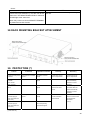
12. RACK MOUNTING BRACKET ATTACHMENT 29
13. PROTECTION 29
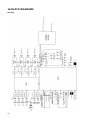
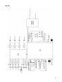
14. BLOCK DIAGRAMS 30
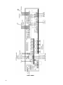
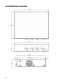
15. DIMENSIONAL DIAGRAM 32
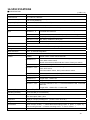
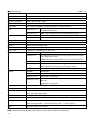
16. SPECIFICATIONS 33

3
1. IMPORTANT SAFETY INSTRUCTIONS
• Read these instructions.
• Keep these instructions.
• Heed all warnings.
• Follow all instructions.
• Do not use this apparatus near water.
• Clean only with dry cloth.
• Do not block any ventilation openings. Install in accordance with the manufacturer's instructions.
• Do not install near any heat sources such as radiators, heat registers, stoves, or other apparatus
(including amplifiers) that produce heat.
• Do not defeat the safety purpose of the polarized or grounding-type plug. A polarized plug has two blades
with one wider than the other. A grounding type plug has two blades and a third grounding prong. The
wide blade or the third prong are provided for your safety. If the provided plug does not fit into your outlet,
consult an electrician for replacement of the obsolete outlet.
• Protect the power cord from being walked on or pinched particularly at plugs,
convenience receptacles, and the point where they exit from the apparatus.
• Only use attachments/accessories specified by the manufacturer.
• Use only with the cart, stand, tripod, bracket, or table specified by the manufacturer,
sold with the apparatus. When a cart is used, use caution when moving the
cart/apparatus combination to avoid injury from tip-over.
• Unplug this apparatus during lightning storms or when unused for long periods of time.
• Refer all servicing to qualified service personnel. Servicing is required when the apparatus has been
damaged in any way, such as power-supply cord or plug is damaged, liquid has been spilled or objects
have fallen into the apparatus, the apparatus has been exposed to rain or moisture, does not operate
normally, or has been dropped.
INSTRUCTIONS ESSENTIELLES POUR LA SÉCURITÉ
• Lire ces instructions.
• Conserver ces instructions pour référence ultérieure.
• Respecter tous les avertissements.
• Suivre toutes les instructions.
• Ne pas utiliser cet appareil à proximité d'eau.
• Nettoyer uniquement à l'aide d'un chiffon sec.
• Ne pas obstruer les orifices de ventilation. Installer conformément aux instructions du fabricant.
• Ne pas installer à proximité de sources de chaleur telles que des radiateurs, des registres thermiques,
des chaudières ou d'autres appareils (notamment des amplificateurs) produisant de la chaleur.
• Ne pas contourner la fonction de sécurité de la fiche polarisée ou de mise à la terre. Une fiche polarisée
est équipée de deux broches, dont l'une est plus large que l'autre. Une fiche de mise à la terre est
équipée de deux broches et d'une troisième pour la mise à la terre. Cette dernière, la plus large, est
prévue à des fins de sécurité. Si la fiche fournie ne peut être insérée dans la prise électrique souhaitée,
consulter un électricien pour faire remplacer cette dernière.
• Protéger le cordon d'alimentation pour éviter qu'il ne soit piétiné ou pincé, notamment au niveau des
fiches, des prises de courant ou de son point de sortie de l'appareil.
• Utiliser uniquement les accessoires spécifiés par le fabricant.
• Utiliser uniquement avec le chariot, support, trépied, la patte de montage ou la table
spécifiés par le fabricant ou vendus avec l'appareil. En cas d'utilisation d'un
chariot,manipuler la combinaison chariot/appareil pour éviter les blessures dues à un
renversement.
• Débrancher cet appareil pendant les orages ainsi que lorsqu'il reste inutilisé pendant
une période prolongée.
• La maintenance de l'appareil doit être confiée à un technicien après-vente qualifié.
Une maintenance s'avère nécessaire si l'appareil est endommagé (au niveau du cordon d'alimentation ou
de la fiche), a été mouillé par un liquide, un objet est tombé à l'intérieur, s'il a été exposé à la pluie ou
l'humidité, s'il ne fonctionne pas normalement ou s'il est tombé.

4
2. SAFETY PRECAUTIONS
• Before installation or use, be sure to carefully read all the instructions in this section for correct and safe
operation.
• Be sure to follow all the precautionary instructions in this section, which contain important warnings and/or
cautions regarding safety.
• After reading, keep this manual handy for future reference.
Safety Symbol and Message Conventions
Safety symbols and messages described below are used in this manual to prevent bodily injury and property
damage which could result from mishandling. Before operating your product, read this manual first and
understand the safety symbols and messages so you are thoroughly aware of the potential safety hazards.
When Installing the Unit
• Do not expose the unit to rain or an environment
where it may be splashed by water or other liquids, as
doing so may result in fire or electric shock.
• Use the unit only with the voltage specified on the
unit. Using a voltage higher than that which is
specified may result in fire or electric shock.
• Do not cut, kink, otherwise damage nor modify the
power supply cord. In addition, avoid using the power
cord in close proximity to heaters, and never place
heavy objects -- including the unit itself–on the power
cord, as doing so may result in fire or electric shock.
• External wiring connected to the terminals marked
with … requires installation by an instructed person.
• The apparatus shall be connected to a mains socket
outlet with a protective earthing connection.
When the Unit is in Use
• Should the following irregularity be found during use,
immediately switch off the power, disconnect the
power supply plug from the AC outlet and contact
your nearest TOA dealer. Make no further attempt to
operate the unit in this condition as this may cause
fire or electric shock.

5
•
If you detect smoke or a strange smell coming from
the unit.
• If water or any metallic object gets into the unit.
• If the unit falls, or the unit case breaks.
• If the power supply cord is damaged (exposure of the
core, disconnection, etc.)
• If it is malfunctioning (no tone sounds.)
• To prevent a fire or electric shock, never open nor
remove the unit case as there are high voltage
components inside the unit. Refer all servicing such
as modification inside the unit to qualified service
personnel.
• Do not place cups, bowls, or other containers of liquid
or metallic objects on top of the unit. If they
accidentally spill into the unit, this may cause a fire or
electric shock.
• Do not insert nor drop metallic objects or flammable
materials in the ventilation slots of the unit's cover, as
this may result in fire or electric shock.
• Do not touch a plug during thunder and lightning, as
this may result in electric shock.
When Installing the Unit
• Never plug in nor remove the power supply plug with
wet hands, as doing so may cause electric shock.
• When unplugging the power supply cord, be sure to
grasp the power supply plug; never pull on the cord
itself. Operating the unit with a damaged power
supply cord may cause a fire or electric shock.
• When moving the unit, be sure to remove its power
supply cord from the wall outlet. Moving the unit with
the power cord connected to the outlet may cause
damage to the power cord, resulting in fire or electric
shock. When removing the power cord, be sure to
hold its plug to pull.
• Avoid installing the unit in humid or dusty locations, in
locations exposed to the direct sunlight, near the
heaters, or in locations generating sooty smoke or
steam as doing otherwise may result in fire or electric
shock.
• To avoid electric shocks, be sure to switch off the
unit's power when connecting speakers.
• The unit is designed exclusively to be mounted in an
equipment rack. Be sure to follow the instructions
below when rack-mounting the unit. Failure to do so
may cause a fire or personal injury.
• Install the equipment rack on a stable, hard floor. Fix it
with anchor bolts or take other arrangements to
prevent it from falling down.
• Be sure to use the screws with a diameter of over 5
mm (0.2") and length of over 12 mm (0.47") to mount
the unit.
• When connecting the unit's power cord to an AC
outlet, use the AC outlet with current capacity
allowable to the unit.
When the Unit is in Use
• Make sure to set all output level controls to 0 position
before power is switched on.
• Loud noise produced when power is switched on with
any of those controls set to the position other than 0
position can impair hearing.
• Do not operate the unit for an extended period of time
with the sound distorting. Doing so may cause the
connected speakers to heat, resulting in a fire.
• Contact your TOA dealer as to the cleaning. If dust is
allowed to accumulate in the unit over a long period of
time, a fire or damage to the unit may result.
• If dust accumulates on the power supply plug or in the
wall AC outlet, a fire may result. Clean it periodically.
In addition, insert the plug in the wall outlet securely.
• Turn off this unit's power switch, and unplug the
power supply plug from the AC outlet for safety
purposes when cleaning or leaving the unit unused for
10 days or more. Doing otherwise may cause a fire or
electric shock.
The lighting flash with arrowhead symbol,
within an equilateral triangle, is intended to
alert the user to the presence of uninsulated
"dangerous voltage" within the product's
enclosure that may be of sufficient magnitude
to constitute a risk of electric shock to persons.
CONSEILS DE SÉCURITÉ
• Avant l'installation ou l'utilisation, lire attentivement l'ensemble des instructions de cette section pour un
fonctionnement correct et sûr.
• Veiller à respecter les précautions recommandées dans cette section, laquelle contient des mises en
garde
• et/ou précautions importantes en matière de sécurité.
• Après lecture, conserver ce manuel à portée de main pour consultation ultérieur
e.

6
Symboles de sécurité et conventions
Les symboles et messages de sécurité décrits ci-dessous sont utilisés dans cette notice pour prévenir tout
dommage corporel ou matériel pouvant résulter d'une mauvaise utilisation. Lire attentivement cette notice
pour comprendre parfaitement les symboles et messages de sécurité afin de prévenir tout risque éventuel.
Lors de l'installation de l'appareil
• Ne pas exposer l'appareil à la pluie et le protéger de
tout contact avec de l'eau ou d'autres liquids afin
d'éviter un incendie ou une electrocution.
• Utilisez l'appareil uniquement avec la tension
spécifiée sur le chargeur. L'utilisation d'une tension
supérieure à celle spécifiée peut être à l'origine d'un
incendie ou d'une electrocution.
• Ne pas couper, entortiller, modifier ou endommager le
cordon d'alimentation. En outre, éviter d'utiliser le
cordon d'alimentation à proximité d'un radiateur et ne
jamais placer d'objets lourds (y compris l'appareil
lui-même) sur le cordon d'alimentation, car ceci
présente un risqué d'incendie ou d'électrocution.
• Les câbles externes branchés aux bornes marquées
de .… doivent être installé par un technicien
spécialement formé.
• L'appareil doit être branché à une prise d'alimentation
avec mise à la terre de protection.
Pendant l'utilisation de l'appareil
• En cas de survenue des irrégularités suivantes
pendant l'utilisation, couper immédiatement
l'alimentation, débrancher la fiche du cordon
d'alimentation de l'adaptateur secteur de la prise
secteur et contacter le représentant TOA le plus
proche. Ne pas essayer pas d'utiliser l'appareil dans
ces conditions sous peine de provoquer un incendie
ou une électrocution.
• Détection de fumée ou d'une odeur inhabituelle
émanant de l'appareil.
• Pénétration d'eau ou d'un objet métallique dans
l'appareil.
• Chute ou endommagement de l'appareil
• Dégradation du cordon d'alimentation (âme du câble
dénudée, déconnexion etc.).
• Dysfonctionnement (absence de tonalité).
• Pour empêcher un incendie ou une électrocution, ne
jamais ouvrir ni ne retirer le boîtier de l'appareil, en
raison de la préswence de pièces à haute tension.
Toutes les opérations de maintenance, notamment
les modifications apportées à l'intérieur de la
machine, doivent être réalisées par un technicien
qualifié.
• Ne pas placer de tasses, bols ou autres recipients
remplis de liquides ou d'objets métalliques au-dessus
de l'appareil. S'ils se répandent par accident sur
l'appareil, ils peuvent provoquer un incendie ou une
électrocution.
• Ne pas insérer ni laisser tomber d'objets métalliques
ou de matériaux inflammables dans les évents de
ventilation du capot de l'appareil sous peine de
provoquer un incendie ou une électrocution.
• Ne pas toucher la fiche du cordon d'alimentation
pendant un orage - Risque d'électrocut.

7
Lors de l'installation de l'appareil
• Ne jamais brancher, ni débrancher la fiche du cordon
d'alimentation avec les mains mouillées. Risque
d'électrocution.
• Pour débrancher le cordon d'alimentation, veiller à le
par sa fiche; ne jamais tirer directement le cordon.
Utiliser l'appareil avec un cordon d'alimentation
endommagé peut présenter un risque d'incendie ou
d'électrocution.
• Lors du déplacement de l'appareil, veiller à retirer la
fiche du cordon d'alimentation de l'adaptateur secteur
de la prise murale. Si le chargeur est déplacé avec le
cordon d'alimentation branché dans la prise, ce
dernier risque d'être endommagé, ce qui présente un
risque d'incendie ou d'électrocution. Pour retirer le
cordon d'alimentation, le tirer par la prise.
• Éviter d'installer l'appareil dans un endroit humide ou
poussiéreux, en plein soleil, à proximité d'un
radiateur, ou dans un endroit dégageant de la fumée
noire ou de la vapeur sous peine de provoquer un
incendie ou une électrocution.
• Pour éviter les chocs électriques, veiller à débrancher
l'appareil avant de connecter les haut-parleurs.
• Cet appareil doit uniquement être monté dans unbâti.
Veiller à suivre les instructions ci-dessous lors du
montage en bâti.
Risque d'incendie ou de blessure corporelle.
• Installer le bâti sur un sol stable.
Le fixer à l'aide de boulons d'ancrage ou d'un autre
dispositif pour l'empêcher de tomber.
• Lors du montage de l'appareil, veiller à utilizer une vis
de plus de 5mm (0,2") de diamètre et de plus de
12mm (0,47") de longueur.
• Pour brancher le cordon d'alimentation à une prise
CA, vérifier l'intensité maximale de l'appareil.
Pendant l'utilisation de l'appareil
• Mettre toutes les commandes du niveau sortie en
position 0 avant que l'alimentation ne soit restituée.Si
l'appareil est mis sous tension alors que ces
commandes ne sont pas en position 0, un bruit fort au
point de dégrader l'audition risque d'être émis.
• Ne pas utiliser l'appareil pendant une période
prolongée si le son est distordu. Les haut-parleurs
branchés risquent de surchauffer et de provoquer un
incendie.
• Pour nettoyer l'appareil, contacter votre revendeur
TOA. L'accumulation de poussière pendant une
période prolongée peut entraîner un incendie ou une
dégradation de l'appareil.
• L'accumulation de poussière sur la fiche du cordon
d'alimentation ou dans la prise secteur présente un
risque d'incendie. Les nettoyer régulièrement. Par
ailleurs, insérer complètement la fiche dans la prise
murale.
• Par mesure de sécurité, lors du nettoyage ou lorsque
l'appareil n'est pas utilisé pendant 10 jours ou plus,
couper l'alimentation, et débrancher la fiche du
cordon d'alimentation de l'adaptateur secteur de la
prise secteur - Risque d'incendie ou d'électrocution.
L'éclair accompagné d'un symbole
représentant une pointe de flèche à l'intérieur
d'un triangle équilatéral avertit l'utilisateur de la
présence d'une "tension dangereuse" à
l'intérieur de l'enceinte dutéléviseur, dont la
magnitude peut êtresuffisante pour constituer
un risque dechoc électrique pour les
personnes
3. GENERAL DESCRIPTION
TOA's MA-725F matrix amplifier and MM-700F is all-in-one solution for multi-channel or multi-zone
applications combined 6x4 audio matrix, DSP and 4ch Class-D amplifier (*) into one chassis. It is equipped
with 4 independent line inputs, 2 MIC/LINE priority inputs. Each output has independent DSP preset
adjustment also comes with input source matrix selection. It features a high power handling (250Wx4 @
70V/100V) (*) and various inputs capabilities. Its wide range of applications include general or emergency
announcement and background music playing at restaurants, pubs, retail stores, schools, offices and etc.
(*) MA-725F only

8
4. FEATURES
• 4 stereo-summing line inputs with matrix routing to 4 amplifier outputs.
• Each line input has input level adjustment and assign restriction setting for each output to prevent wrong
routing selection.
• 2 priority MIC/LINE inputs with different priority level for paging or other pre-recorded source can override
the selected line input on assigned output channels.
• Each priority input also has input level, mute sensitivity and mute hold time adjustments.
• Each output channel is equipped with 250W Class-D amplifier at 70V/100V output voltage selectable with
independent DSP preset selection and 50Hz HPF for the protection of connected speakers. (*)
• Selectable DSP preset selections include general EQs, like Loudness curves, TOA speaker EQs and
crossover settings to be used with sub-woofers.
• Each output channel also has auxiliary line output to deliver the audio to other system.
• This matrix doesn’t need any GUI or network connection for setup at site. (Maintenance purpose only)
• Optional wall mount remote control, WP-700 can be connected via CAT-5 straight LAN cable to control
line input selections and output volume of each output.
• Class-D amplifier has a lot of protection features against over current, high temperature and short circuit
of speaker lines at each output channel individually. (*)
• Power supply with Power Factor Correction for reduced power consumption and world-wide operating
range. (*)
(*) MA-725F only
5. HANDLING PRECAUTIONS
• Keep the input cable away from the output cable. If installed close to each other, oscillation could occur.
• To avoid unit failures, never connect outputs of 2 or more channels in parallel.
• Only connect speakers with an impedance equal to or greater than those specified. Connecting speakers
with a smaller impedance than specified could cause damage to the unit.
• Install the unit in locations where the temperature is between –10°C and +40°C (14°F and 104°F) and the
moisture is less than 90%RH (no dew condensation must be formed).
• To clean, be sure to first turn off this unit's power switch, then wipe with a dry cloth. When the unit gets
very dirty, use a cloth damped in a neutral cleanser. Never use benzene, thinner, alcohol, or
chemically-treated cleaning cloth because such volatile liquids could deform or discolor the unit.

9
6. INSTALLATION PRECAUTIONS
• When mounting the unit in an equipment rack, the inside of the rack must be sufficiently ventilated.
To achieve sufficient ventilation, remove all panels on the rear of the rack.
• When mounting the unit in the rack, also mount a Perforated Panel larger than 1U in size
(1) at the top and the bottom of the rack, and
(2) above and below every 5 units.
* 1U size = 44.5 mm or 1.75" (reference size)

10
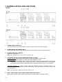
7. NOMENCLATURE AND FUNCTIONS
[Front]
1 POWER SIWITCH [ON /OFF]
Press this switch to turn on the amplifier, press the switch again to turn off the amplifier.
2. POWER INDICATOR [POWER] (Blue)
During the power on process the indicator flashes, after amplifier is ready, the indicator lights.
3. CH1 OUTPUT LEVEL CONTROL
Adjust CH1 output level
Note: The functionality of CH2, CH3, CH4 is the same as CH1.
4. CH1 SIGNAL, PEAK, PROTECT INDICATOR (Green, Red, Red)
SIGNAL Indicator: When output level exceeds -36 dBV, the SIGNAL indicator lights.
PEAK Indicator: Lights red when an output signal clips (distortion occurs).
Note:
When the Peak indicator lights, turn the output level control (3) counterclockwise until its light
extinguishes or decrease the input signal level of the connected external device. Operating the
unit while the Peak indicator remains lights may cause the protection circuitry to be activated.
PROTECT Indicator (*): Lights or blinks when the protection circuitry is activated. (See p. 27;
Protection Operation List.) When the power is switched on, this indicator lights for about 2 seconds and
then extinguishes.
Note: The functionality of CH2, CH3, CH4 is the same as CH1.
5. LINE 1, LINE 2, LINE 3, LINE 4 INPUT SIGNAL INDICATOR (Green)
When LINE 1, LINE 2, LINE 3, LINE 4 input signal is exceed -47dBV, the indicator lights.

11
6. PRIORITY INPUT SIGNAL INDICATOR [PRIORITY 1, PRIORITY 2] (Green, Green)
PRIORITY INPUT SIGNAL1 Indicator: When the priority input 1 signal (14) exceed -36dBV
(line)/-86dBV (mic) the indicator lights.
PRIORITY INPUT SIGNAL2 Indicator: When the priority input 2 signal (14) exceed -36dBV
(line)/-86dBV (mic), the indicator lights.
7. CH1 PRIORITY INDICATOR [PRIORITY1, PRIORITY2] (Green, Green)
PRIORITY 1 Indicator:When PRIORITY 1 is activated and assigned to CH1 output, the indicator lights.
PRIORITY 2 Indicator:When PRIORITY 2 is activated and assigned to CH1 output, the indicator rights.
Note: 1. When PRIORITY MIX 1+2 switch is turned on and activated, these two indicator light at the same time.
2. The functionality of CH2, CH3, CH4 is the same as CH1.
8. CH1 PRIORITY INDICATOR [REMOTE] (Yellow)
When remote control panel WP-700 is connected to CH1 of REMOTE TERMINALS, the indicator lights.
At this time, both output level and input source selection could be changed by connected WP-700.
Note: 1. When WP-700 is connected, CH1 OUTPUT LEVEL CONTROL (3) and CH1 INPUT SELECT SWITCH (5)
on the front panel are defeated and controlled by WP-700.
2. When WP-700 is disconnected, the output level goes back to the setting of CH1 OUTPUT LEVEL
CONTROL( 3)
3. The functionality of CH2, CH3, CH4 is the same as CH1.
9. CH1 INPUT SELECT SWITCH 1 - 4
Select from LINE 1-4 inputs as the input source for amplifier CH1 output. Select again on the previous
selected input turns off the selection of input source.
Note: The functionality of CH2, CH3, CH4 is the same as CH1.
10. CH1 INPUT SELECT INDICATOR [1, 2, 3, 4] (Green)
The led will light with respect to the input select by the INPUT SELECT SWITCH (5) other channel which
is not selected will turn off.
Note: The functionality of CH2, CH3, CH4 is the same as CH1.
(*) MA-725F only
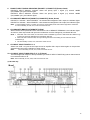
[Rear]

12
11. AC inlet
Connect the supplied power cord to this inlet. The socket-outlet should be installed near the equipment
and the plug (disconnected device) shall be easily accessible.
12. Functional ground terminal [SIGNAL GND]
Hum noise may be generated when external equipment is connected to the unit. Connecting this
terminal to the functional ground terminal of the external equipment may reduce the hum noise.
13. LINE 1, LINE 2, LINE 3, LINE 4 INPUT TERMINAL
10 kΩ,–10 dB*,unbalanced RCA Jack (Upper and lower of RCA input signal is mixed)
Connect music source equipment: e.g: CD players.
14. LINE 1, LINE 2, LINE 3, LINE 4 INPUT LEVEL CONTROL
Adjust the input level (sensitivity) of LINE 1, LINE 2, LINE 3, LINE 4.
15. ASSIGNMENT RESTRICTION DIP SWITCHES (LINE 1, LINE 2, LINE 3, LINE 4)
Assign restriction LINE 1, LINE 2, LINE 3, LINE 4 to CH1, CH2, CH3, CH4 outputs.
LINE 1 ASSIGNMENT RESTRICTIONS:
Switch No. ON OFF
1 LINE 1 can’t be assigned to CH1 LINE 1 can be assigned to CH1
2 LINE 1 can’t be assigned to CH2 LINE 1 can be assigned to CH2
3 LINE 1 can’t be assigned to CH3 LINE 1 can be assigned to CH3
4 LINE 1 can’t be assigned to CH4 LINE 1 can be assigned to CH4
Note: 1)
The functionality for LINE 2, LINE 3, LINE4 is the same as LINE 1.
2) When the assignment restriction is set, both INPUT SELECT SWITCH (10) or connected
WP-700, are not allowed to select the restricted channel.
16. MIC/LINE input terminal (PRIORITY 1, PRIORITY 2)
MIC: 2.2K, –60 dB*/ LINE: 2.2K, –10 dB*, electronically-balanced inputs of 3-pin removable terminal
block type.
Connect microphone or line level music source equipment. MIC/LINE gain could be from the PRIORITY
FUNCTIONAL DIP SWITCH (20) #6.
17. MIC/LINE input level control (PRIORITY 1, PRIORITY 2)
Adjust the input level (sensitivity) of the MIC/LINE
18. Manual mute terminal
Open voltage: DC 3.3V, Short current: <5mA
1) When (+), (-) shorted: The selected LINE 1, LINE 2, LINE3, LINE4 input signal to CH1, CH2, CH3,
CH4 output will be muted, and switch to the page channel (1st ~4th switch of (20)) that have been
assigned by PRIORITY 1, PRIORITY 2 inputs.
2) When (+), (-) opened:CH 1, CH 2, CH 3, CH 4 output will gradually recovered from the previous
assigned LINE 1, LINE 2, LINE3, LINE4 signal. The recovery time is controlled by the HOLD TIME
control (19).

13
19. MUTE SENSE control (PRIORITY 1, PRIORITY 2)
Adjust the threshold (sensitivity) of the mute function of the PRIORITY 1, PRIORITY 2 inputs. In other
words, if PRIORITY 1, PRIORITY 2 input signal exceed the threshold that set by MUTE SENSE, it will
mute the LINE 1, LINE 2, LINE 3, LINE 4 signal to CH1, CH2, CH3, CH4 outputs. Rotate clockwise will
raise the sensitivity, counter-clockwise will lower the sensitivity.
20. HOLD TIME control (PRIORITY 1, PRIORITY 2)
Adjust the recovery time of the LINE 1, LINE 2, LINE 3, LINE 4 to CH1, CH2, CH3, CH4 outputs. Rotate
clockwise will increase the recovery time (maximum 10sec), counter-clockwise will decrease the
recovery time (minimum 50ms)
21. PRIORITY FUNCTIONAL DIP SWITCH (PRIORITY 1, PRIORITY 2)
Control the functionality of the PRIORITY 1 and PRIORITY 2
Switch No. ON OFF
1 PRIORITY 1/2 can be switched to CH1 output PRIORITY 1/2 cannot be switched to CH1 output
2 PRIORITY 1/2 can be switched to CH2 output PRIORITY 1/2 cannot be switched to CH2 output
3 PRIORITY 1/2 can be switched to CH3 output PRIORITY 1/2 cannot be switched to CH3 output
4 PRIORITY 1/2 can be switched to CH4 output PRIORITY 1/2 cannot be switched to CH4 output
5 The mute function is controlled by the PRIORITY
1/2 input signal or manual mute (16)
The mute function is only controlled by the
manual mute (16)
6 PRIORITY 1/2 input gain switch to MIC level PRIORITY 1/2 input gain switch to LINE level
22. PRIORITY MIX1+2 switch
Control the input mode of the PRIORITY 1/2
ON OFF
PRIORITY 1 and PRIORITY 2 will be mixed and output
to CH1, CH2, CH3, CH4 when mute activated. The
PRIORITY FUNCTIONAL DIP SWITCH (20), MUTE
SENSE control (18), HOLD TIME control (19) will be
followed by PRIORITY 1’s setting
The PRIORITY 1 has the higher priority level than
PRIORITY 2. When There is mute function activated.
Unit will output PRIORITY 1’s input first.
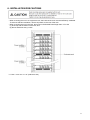
23. EQ BANKS and PRESETS SELECTION
The 2-bit DIP switch select the bank of respect to the 16 EQ presets. Total 4 banks.
The 4-bit rotary switch selects 16 EQ presets from each banks.
Note: The functionality of CH2, CH3, CH4 is the same as CH1.
Please see page 23, "11.2 EQ preset selections" for more details.
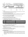
24. HPF SWITCH (*)
Control the activation of HPF (High Pass filter) on outputs.
ON OFF
The CH1, CH2, CH3, CH4 will has 50Hz, -12dB/oct. high
pass filter on output. This is useful to protect the speaker
when the transformer of the distribute speaker couldn’t
handle low frequency.
The output frequency response is flat from 20Hz to
20kHz.
25. REMOTE TERMINALS (CH1, CH2, CH3, CH4 remote controls)
RJ45 connector, use for connecting the remote module WP-700.
After connecting WP-700 could provide the following functionality:
1) Switch the input source LINE 1, LINE 2, LINE 3, LINE 4 to CH1, CH2, CH3, CH4 outputs.
2) Adjust the volume of connected channel.
Note: When the WP-700 is connected, the OUTPUT LEVEL CONTROL (3) on front panel and INPUT
SELECT SWITCH (10) won’t be functional. It means this two function will follow WP-700 setting. Also,
the REMOTE INDICATOR (8) will light.

14
26. REMOTE LINK SWITCH (CH1-2, CH3-4)
CH1-2:
ON OFF
CH1, CH2 could control the CH1 and CH2’s volume and
input selection by one WP-700 at the same time. The
REMOTE INDICATOR on CH1 and CH2 will light at the
same time.
Note: Only connect to CH1’s REMOTE TERMINAL to
present remote link function
CH1, CH2’s volume is controlled separated by two
WP-700.
CH3-4:
ON OFF
CH3, CH4 could control the CH1 and CH2’s volume and
input selection by one WP-700 at the same time. The
REMOTE INDICATOR on CH3 and CH4will light at the
same time.
Note: Only connect to CH3’s REMOTE TERMINAL to
present remote link function
CH3, CH4’s volume is controlled separated by two
WP-700.
27. 70V/100V OUTPUT MODE SWITCH (*)
Adjust the amplifier output mode
70V 100V
Maximum output will be set to 70Vrms
(maximum load impedance = 20ohm)
Maximum output will be set to 100Vrms
(maximum load impedance = 40ohm)
28. POWER REMOTE TERMINAL
Open voltage: 3.3V, Shorted current: <1mA
When AC mains is connected to (11) and POWER SWITCH (1) is in ON position, shorted will turn off the
power amplifier and all of the indication for power saving. Open will in normal operation.
29. LAN PORT
RJ-45 10/100M Ethernet connection.
Maintenance purpose only for factory.
30. LINE OUTPUT TERMINAL (CH1, CH2, CH3, CH4) (*)
600Ω, 0dB*, RCA connector.
Auxiliary line level output (just before the amplifier input).
31. MOH OUTPUT TERMINAL
600Ω, 0dB*, transformer- isolated balanced output, removable terminal block type.
LINE4 input is assigned to this output.
Note:
1. The MOH output level is not affected by the input level control of the LINE4.
2. MOH output doesn’t have MUTE functionality.
3. MOH output doesn’t have EQ functionality.
32. MOH OUTPUT INPUT LEVEL CONTROL
Adjust the input level of the MOH OUTPUT.
33. SPEAKER OUTPUT TERMINAL (CH1, CH2, CH3, CH4)
MA-725F:
70V/100V output (select by the 70V/100V OUTPUT MODE SWITCH (26)), removable terminal block
type. Connect to speaker.
MM-700F:
600Ω, 0dB*, removable terminal block type. Line level output.
* 0 dB = 1Vrms
(*) MA-725F only

15
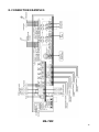
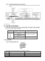
8. CONNECTION EXAMPLES
MA-725F

16
MM-700F

17
9. CONNECTION
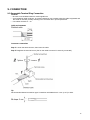
9.1. Removable Terminal Plug Connection
Cautions
• Be sure to use shielded cables for audio signal lines.
• Avoid soldering cable conductor, as contact resistance may increase when the cable is tightened and
the solder is crushed, possibly resulting in an excessive rise in joint temperatures.
• Use cables of AWG 12 – 24.
Cable end treatment
Connector connections
Step 1. Loosen the terminal screw, then insert the cable.
Step 2. Retighten the terminal screw. (Pull on the cable to ensure it is securely connected.)
Tip
Recommended slotted screwdriver type: Screwdriver with blade that is 3 mm (0.12") in width.

18
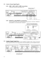
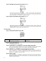
9.2. How to Connect Input Signals
9.2.1. LINE 1, LINE 2, LINE 3, LINE 4 connections
L and R line signals are mixed inside the unit.
9.2.2. PRIORITY 1 and PRIORITY 2 connections
Use the supplied Small type removable terminal plug (5 pins) for connection. PRIORITY 1
and PRIORITY 2 can be set to MIC or LINE input.
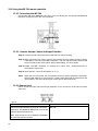
9.3. Speaker Output Connections
The unit can operated at 70V or 100V line high-impdedance speakers Class 2 wiring may be used.
Using supplied removable terminal plug (2 pins), connect the speaker line to each speaker terminals.

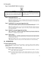
19
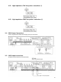
9.3.1. High-impdedance 70V line speaker connections (*)
9.3.2. High-impdedance 100V line speaker connections (*)
9.4. MOH Output Connections
Use the supplied removable terminal plug (3 pins) for connection.
9.5. LINE output connections
Auxiliary line level output for zone expansion.

20
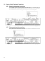
9.6. Remote Control Equipment Connections
9.6.1. Manual muting terminal connections
If a no-voltage contact is connected, closing the contact allows the pre-determined input
channel volume to be reduced by a preset level of attenuation.
If a microphone with a contact is connected as shown in Connection (p. 12), the audio of
other channels will be muted for as long as the microphone’s talk switch is pressed.
9.6.2. Power remote terminal connections
If a no-voltage contact is connected, closing the contact allows the amplifier goes into power
saving mode. All of the indication will be turn off.
La page est en cours de chargement...
La page est en cours de chargement...
La page est en cours de chargement...
La page est en cours de chargement...
La page est en cours de chargement...
La page est en cours de chargement...
La page est en cours de chargement...
La page est en cours de chargement...
La page est en cours de chargement...
La page est en cours de chargement...
La page est en cours de chargement...
La page est en cours de chargement...
La page est en cours de chargement...
La page est en cours de chargement...
La page est en cours de chargement...
La page est en cours de chargement...
-
 1
1
-
 2
2
-
 3
3
-
 4
4
-
 5
5
-
 6
6
-
 7
7
-
 8
8
-
 9
9
-
 10
10
-
 11
11
-
 12
12
-
 13
13
-
 14
14
-
 15
15
-
 16
16
-
 17
17
-
 18
18
-
 19
19
-
 20
20
-
 21
21
-
 22
22
-
 23
23
-
 24
24
-
 25
25
-
 26
26
-
 27
27
-
 28
28
-
 29
29
-
 30
30
-
 31
31
-
 32
32
-
 33
33
-
 34
34
-
 35
35
-
 36
36


Optimus MA-725F-EB Le manuel du propriétaire
- Taper
- Le manuel du propriétaire
dans d''autres langues
- English: Optimus MA-725F-EB Owner's manual
Documents connexes
Autres documents
-
TOA BG-2480D Manuel utilisateur
-
TOA A-230 HV Specification Data
-
-
-
Sony XM-6ES Manuel utilisateur
-
Adastra 952.996 Mode d'emploi
-
-
LD Systems AM 8 Manuel utilisateur
-
Yamaha n12 Le manuel du propriétaire
-
Episode ESA-70V2CH-500W Guide d'installation