Best AEIC35SB Manuel utilisateur
- Catégorie
- Hottes
- Taper
- Manuel utilisateur

ENGLISH.................................... 2
FRANÇAIS.................................25
ESPAÑOL.................................. 49
In USA - BEST Hartford, Wisconsin
In CANADA - BEST Drummondville, QC, Canada
REGISTER YOUR PRODUCT ONLINE AT : www.BestRangeHoods.com/register
For additional Information visit www.BestRangeHoods.com
Models IC35I90B & IC35I90W

- 2 -
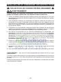
READ AND SAVE THESE INSTRUCTIONS
WARNING
TO REDUCE THE RISK OF FIRE, ELECTRIC SHOCK, OR INJURY TO PERSONS,
OBSERVE THE FOLLOWING:
1. Use this unit only in the manner intended by the manufacturer. If you have questions,
contact the manufacturer at the address or telephone number listed in the warranty.
2. Before servicing or cleaning unit, switch power off at service panel and lock service
panel to prevent power from being switched on accidentally. When the service discon-
necting means cannot be locked, securely fasten a prominent warning device, such
as a tag, to the service panel.
3. Installation work and electrical wiring must be done by a qualified person(s) in ac-
cordance with all applicable codes and standards, including fire-rated construction
codes and standards.
4. Sufficient air is needed for proper combustion and exhausting of gases through the
flue (chimney) of fuel burning equipment to prevent backdrafting. Follow the heating
equipment manufacturer’s guidelines and safety standards such as those published
by the National Fire Protection Association (NFPA), and the American Society for
Heating, Refrigeration and Air Conditioning Engineers (ASHRAE), and the local code
authorities.
5. When cutting or drilling into wall or ceiling, do not damage electrical wiring and other
hidden utilities.
6. Ducted fans must always be vented to the outdoors.
7. Do not use this unit with any separate solid-state speed control device.
8. To reduce the risk of fire, use only metal ductwork.
WARNING - Improper grounding can result in a risk of electric shock.
Consult a qualified electrician if the grounding instructions are not completely understood,
or if doubt exists as to whether the appliance is properly grounded.
Do not use an extension cord. If the power supply cord is too short, have a qualified
electrician install an outlet near the appliance.
!
INTENDED FOR DOMESTIC COOKING ONLY
!

- 3 -
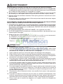
!
CAUTION
1. For indoor use only.
2. To reduce risk of fire and to properly exhaust air, be sure to duct air outside. Do not
vent exhaust air into spaces within walls or ceilings or into attics, crawl spaces, or
garages.
3. Take care when using cleaning agents or detergents.
4. Avoid using food products that produce flames under the Range Hood.
5. For general ventilating use only. Do not use to exhaust hazardous or explosive
materials and vapors.
6. To avoid motor bearing damage and noisy and/or unbalanced impellers, keep drywall
spray, construction dust, etc. off power unit.
7. Your hood motor has a thermal overload which will automatically shut off the motor
if it becomes overheated. The motor will restart when it cools down. If the motor
continues to shut off and restart, have the hood serviced.
8. For best capture of cooking impurities, the bottom of the hood should be a minimum
of 24" and a maximum of 30" above the cooking surface. See “Determine the Hood
Mounting Height” section for mounting restrictions.
9. Two installers are recommended because of the large size and weight of this hood.
10. This product is equipped with a thermostat which may start blower automatically. To
reduce the risk of injury and to prevent power from being switched on accidentally,
switch power off at service panel and lock or tag service panel.
11. Please read specification label on product for further information and requirements.
WARNING
TO REDUCE THE RISK OF A RANGE TOP GREASE FIRE:
A. Never leave surface units unattended at high settings. Boilovers cause smoking and
greasy spillovers that may ignite. Heat oils slowly on low or medium settings.
B. Always turn hood ON when cooking at high heat or when flambeing food (i.e. Crepes
Suzette, Cherries Jubilee, Peppercorn Beef Flambe’).
C. Clean ventilating fans frequently. Grease should not be allowed to accumulate on fan
or filter.
D. Use proper pan size. Always use cookware appropriate for the size of the surface
element.
TO REDUCE THE RISK OF INJURY TO PERSONS IN THE EVENT OF A RANGE TOP
GREASE FIRE, OBSERVE THE FOLLOWING:*
1. SMOTHER FLAMES with a close-fitting lid, cookie sheet, or metal tray, then turn off
the burner. BE CAREFUL TO PREVENT BURNS. If the flames do not go out imme-
diately, EVACUATE AND CALL THE FIRE DEPARTMENT.
2. NEVER PICK UP A FLAMING PAN - You may be burned.
3. DO NOT USE WATER, including wet dishcloths or towels - violent steam explosion
will result.
4. Use an extinguisher ONLY if:
A. You know you have a Class ABC extinguisher and you already know how to oper-
ate it.
B. The fire is small and contained in the area where it started.
C. The fire department is being called.
D. You can fight the fire with your back to an exit.
* Based on “Kitchen Fire Safety Tips” published by NFPA.

- 4 -
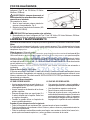
OPERATION
Controls
The hood is operated using the (5) push buttons located on the underside of the
hood. Fig. 1.
Ten Minute Delay
Press Speed 1, Speed 2, or Speed 3 for two seconds when the blower is running at
the selected speed. The LED below the button will start blinking to display the delay
function. After ten minutes the blower will automatically turn off. If you change the
speed while the timer is running, the function will not deactivate. To deactivate the
function, press the button with the blinking LED for two seconds. Note: The delay
is not available for Speed 4.
Filter Alarm
After 30 hours of blower operation, the filter alarm is activated and all of the LED
indicators will turn on. The alarm is activated when the motor is off and the LEDs will
remain on for 30 minutes. To deactivate the alarm, press any of the control buttons
for two seconds while the LEDs are on.
After 120 hours of blower operation the charcoal filter alarm is activated and all of
the LED indicators will blink. The alarm is activated when the motor is off and the
LEDs will remain on for 30 minutes. To deactivate the alarm, press any of the control
buttons for two seconds while the LEDs are on.
HEAT SENTRY™
Your hood is equipped with a HEAT SENTRY™ thermostat. This thermostat is a
device that will turn on or speed up the blower if it senses excessive heat above
the cooking surface.
1) If blower is OFF - it turns blower ON to HIGH speed.
2) If blower is ON at a lower speed setting - it turns blower up to HIGH speed.
When the temperature level drops to normal, the blower will return to its original
setting.
WARNING
The HEAT SENTRY™ thermostat can start the blower even if the hood is turned
OFF. When this occurs, it is impossible to turn the blower OFF with its switch.
If you must stop the blower, do it from the main electrical panel.
FIG. 1

- 5 -
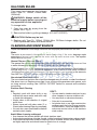
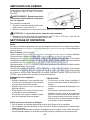
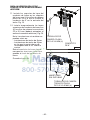
HALOGEN BULBS
This range hood requires two halogen
bulbs (Type T4, 120Volt, 25Watt Max,
G9 Base).
WARNING: Always switch off the
electrical supply before carrying out
any operation on the appliance.
To change bulbs:
1. Open the cover by prying from the
proper slots. Fig. 2.
2. Remove the bulbs by pulling sideways. (DO NOT ROTATE).
!
CAUTION: Bulbs may be hot.
3. Replace with Type T4, 120Volt, 25Watt Max, G9 Base halogen bulbs. Do not
touch replacement bulbs with bare hands!
CLEANING AND MAINTENANCE
Proper maintenance of the Range Hood will assure proper performance of the unit.
Motor
The motor is permanently lubricated and never needs oiling. If the motor bearings make
excessive or unusual noise, replace the motor with the exact service motor. The impeller
should also be replaced.
Grease Filter and Charcoal Filters
The grease filter should be cleaned frequently, typically when the filter alarm turns on. Use
a warm dishwashing detergent solution. Grease filter is dishwasher safe.
Clean all-metal filters in the dishwasher using a non-phosphate detergent. Discoloration of
the filter may occur if using phosphate detergents, or as a result of local water conditions
- but this will not affect filter performance. This discoloration is not covered by the warranty.
See “INSTALL FILTERS” section for removal and installation instructions.
Non-ducted Recirculation Filter
The non-ducted recirculation filter should be changed every 6 months or when the charcoal
filter alarm turns on. Replace more often if your cooking style generates extra grease, such
as frying and wok cooking. See “INSTALL FILTERS” section for removal and installation
instructions.
Stainless Steel Cleaning
DO:
• Regularly wash with clean cloth or rag
soaked with warm water and mild soap
or liquid dish detergent.
• Always clean in the direction of original
polish lines.
• Always rinse well with clear water (2 or
3times) after cleaning. Wipe dry completely.
• You may also use a specialized household
stainless steel cleaner.
DON’T:
•
Use any steel or stainless steel wool or any
other scrapers to remove stubborn dirt.
• Use any harsh or abrasive cleansers.
• Allow dirt to accumulate.
• Let plaster dust or any other construction
residues reach the hood. During construc-
tion/renovation, cover the range hood to
make sure no dust sticks to the stainless
steel surface.
Avoid: When choosing a detergent
• Any cleaners that contain bleach will attack stainless steel
• Any products containing: chloride, fluoride, iodide, bromide will deteriorate surfaces rapidly.
• Any combustible products used for cleaning such as acetone, alcohol, ether, benzol, etc.,
are highly explosive and should never be used close to a range.
FIG. 2

- 6 -
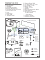
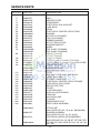
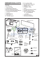
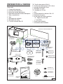
PREPARE THE HOOD
Unpack hood and check contents.
You should receive:
1 - Hood Body
2 - Decorative Glass Panel
2- Telescopic Mounting Arms
2 - Decorative Telescopic Arm Covers
1 - Electrical Box & Cover
2 - Cover
1 - Wiring Clamp
2 - Cable Clamp
12 - Lag Bolts, M6x60
HOOD BODY
MACHINE
SCREWS,
M4 x 8 (16)
FIG. 3
16 - Machine Screws, M4x8
8 - Flat Head Screws, 3.9 x 6 mm
4 - Lock Washers, 3.9 mm
2 - Washers, 16 mm
12 - Washer, 12.5 mm
1 - Grommet
4 - Brass Decorative Screws, M4x16
4 - Rubber Protectors
2 - Set Screw Kits containing:
13 - M6 Set Screws
1 - Allen Wrench
1 - Installation Template
1 - Installation Instructions
DECORATIVE GLASS PANEL
INSTALLATION TEMPLATE
TELESCOPIC
MOUNTING
ARMS (2)
DECORATIVE
TELESCOPIC ARM
COVERS (2)
COVER (2)
RUBBER
PROTECTORS (4)
ELECTRICAL
BOX & COVER
M6x60
LAG
BOLT S (12)
WIRING
CLAMP
GROMMET
BAG OF
PARTS
CABLE
CLAMPS (2)
BRASS
DECORATIVE
SCREW,
M4 x 16 (4)
FLAT HEAD
SCREWS,
3.9 x 6 mm (8)
WASHERS,
12.5 MM (12)
LOCK WASHERS, 3.9 MM (4)
WASHERS,
16 MM (2)

- 7 -
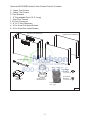
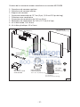
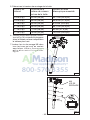
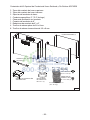
Optional AEIC35SB Ducted & Non-Ducted Flue Kit Contents
2 - Upper Flue Covers
2 - Lower Flue Covers
2- Flue Brackets
1 - 5" Expandable Duct (12.5" Long)
1 - Non-Duct Plenum
1- 6" Duct Connector
2 - 6" to 5" Duct Reducers
4 - 3.9 x 6 mm Flat Head Screws
8 - 3.9 x 9 mm Pan Head Screws
UPPER FLUE COVERS (2)
LOWER FLUE COVERS (2)
FLUE BRACKETS (2)
NON-DUCT
PLENUM
6" DUCT CONNECTOR
6" TO 5" DUCT
REDUCERS (2)
5" Expandable Duct
(12.5" long)
FLAT HEAD
SCREWS,
3.9 x 6 mm (4)
PANHEAD
SCREWS,
3.9 x 9 mm (8)
FIG. 4

- 8 -
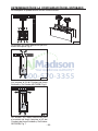
This hood can be ducted in three different configurations:
Non-Ducted with Decorative Support
Arm Covers. Fig. 5.
Ducted with Decorative Flue (requires
AEIC35SB Ducted & Non-Ducted Flue
Kit). Fig. 6.
Non-Ducted with Decorative Flue Cov-
ers (requires AEIC35SB Ducted & Non-
Ducted Flue Kit). Fig. 7.
DETERMINE DUCTING CONFIGURATION
FIG. 5
FIG. 6
FIG. 7

- 9 -
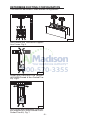
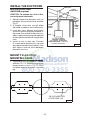
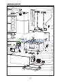
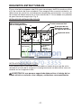
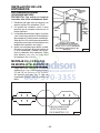
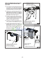
The total weight of the hood is 63 lbs as supplied and 82 lbs when the ducted flue
kit is used. Special structural considerations must be made to ensure proper instal-
lation. The mounting brackets need to be mounted to 2" nominal lumber. Hollow wall
anchors of any kind should not be used. Fig. 8.
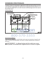
ROUGH-IN DETAILS
ROUGH-IN ELECTRICAL
This hood is hard wired via a junction box located in the hood canopy. Incoming
power should be located as shown on the drawings above.
WARNING: Electrical wiring must be done by a qualified person in ac-
cordance with all applicable codes and standards.
Ceiling
Joist
2x4 Cross Brace
2x8 Blocking
must be flush
with ceiling joist
6" Duct
outline
8
1
4
"
6
1
8
"
8
1
4
"
22
1
2
"
6
1
4
"
8"
2
3
4
"
Possible incoming
power locations
Control Panel Side
(Ducted only)
FIG. 8
STRUCTURAL REQUIREMENTS

- 10 -
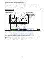
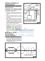
ROOF CAP
6-INCH
ROUND DUCT
HOOD
UNDER
EAVE
VENT
6-INCH
ROUND
ELBOW
24" TO 30" ABOVE
COOKING SURFACE
(see “MOUNT TELESCOPIC
MOUNTING ARMS” section for
mounting restrictions)
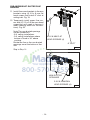
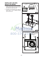
INSTALL THE DUCTWORK
DUCTED HOODS ONLY
(AEIC35SB required)
CAUTION: To reduce the risk of fire,
use only metal ductwork.
1. Decide where the ductwork will run
between the hood and the outside.
Fig. 9.
2. A straight, short duct run will allow
the hood to perform most efficiently.
3. Long duct runs, elbows, and transi-
tions will reduce the performance of
the hood. Use as few of them as pos-
sible. Larger ducting may be required
for best performance with longer duct
runs.
4. Install a roof or wall cap. Connect
6" round metal ductwork to cap and
work back towards hood location. Use
duct tape to seal the joints between
ductwork sections.
FIG. 9
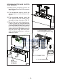
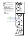
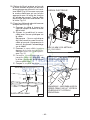
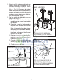
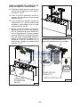
MOUNT TELESCOPIC
MOUNTING ARMS
1. Tape the mounting template in place
and drill (12) 1/8" diameter holes at the
center locations shown. Fig. 10. When
complete remove template from ceil-
ing.
1/8 IN. DIAMETER
LOCATIONS (12)
FIG. 10

- 11 -
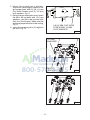
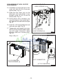
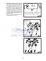
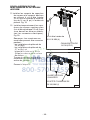
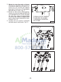
2. Mount the junction box to the tele-
scopic arm (see rough in sketch to se-
lect proper arm) with (2) 3.9x 6mm
Flat Head Screws and (2) 3.9 mm
lock washers. Fig. 11.
3. Mount the two telescopic arms. Insert
the M6x60 lag bolts with 12.5mm
washers - mount in the two key hole
slots first (2 bolts/arm). Make sure the
arms are perpendicular to the ceiling.
Fig 12.
4. Insert the remaining four (4) lag bolts
per arm. Fig. 13.
FIG. 11
FIG. 12
FIG. 13
3.9 X 6 MM FLAT HEAD
SCREW AND 3.9 MM
LOCK WASHER
M6X60
LAG BOLTS
12.5 MM
WASHERS

- 12 -
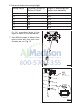
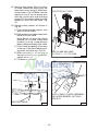
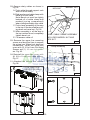
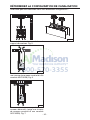
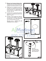
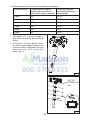
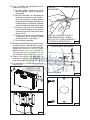
5. Determine the hood mounting height.
Ceiling Height Distance Cooktop to
Bottom of Hood
Height of assembled tele-
scopic arm assembly
8 ft 24" 23.5"
8 ft 26" 21.5"
9 ft 25" 34.5"
9 ft 26" 33.5"
9 ft 28" 31.5"
9 ft 30" 29.5"
6. Insert lower telescopic arm (see
Fig. 14.) and adjust length to the
height as shown in the table above.
7. Insert M6 set screws in all holes that
make contact with the lower arm.
Make sure there are a minimum of
6screws per arm. Fig. 15.
FIG. 15
FIG. 14
M6
SET
SCREWS

- 13 -
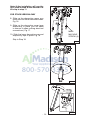
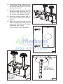
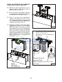
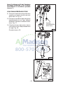
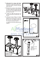
Note: If the installation will use the
AEIC35SB Ducted & Non-Ducted Flue
Kit skip to step 11.
FOR STOCK VERSION ONLY
8. Slide on the decorative upper arm
cover with four M4x8 machine screws.
Fig. 16.
9. Slide on the decorative cover tape
temporarily in place (you will need
to remove it when making electrical
connections). Fig. 17.
10. Slide the lower decorative arm and
temporarily tape in place. Fig. 18.
Skip to Step 18.
FIG. 16
FIG. 17
FIG. 18
M4X8
MACHINE
SCREW (4)

- 14 -
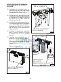
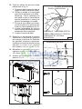
FOR AEIC35SB KIT DUCTED FLUE
VERSION
11. Install flue cover brackets to the arm
brackets using (4) 3.9x6mm flat
head screws and install 6" duct at
ceiling inlet. Fig. 19.
12. Temporarily install upper flue cov-
ers with (4) 2.9x9.5mm pan head
screws(you will need to remove it
when making electrical connec-
tions). Fig. 20.
Note: The non-ducted openings
can be covered on:
- 8-ft. ceiling installations.
- 9-ft. ceiling installations where
bottom of hood is 30" above
cooktop.
Rotate the flue so the non-ducted
openings are at the bottom of the
flue.
Skip to Step 24.
FIG. 19
FIG. 20
3.9 X 6 MM FLAT
HEAD SCREWS (4)
2.9 X 9.5 MM PAN
HEAD SCREWS (4)
6" DUCT
NON-DUCTED
OPENINGS

- 15 -
FOR AEIC35SB KIT NON- DUCTED
FLUE VERSION
13. Assemble non-duct plenum to duct
cover rails with (4) 3.9 x 6 mm pan
head screws. Fig. 21.
14. Slide the flue cover rails on the
telescopic arms and attach to arm
brackets using (4) 3.9 x 9 mm flat
head screws. Fig. 21.
15. Install plastic duct connector into
non-duct plenum, then install the 6"
to 5" reducer and seal with duct tape.
Fig. 22.
16. Install 5"x 12.5" expandable duct and
seal with duct tape. Fig. 22.
1 7. Temporarily install upper flue covers
with (4) 3.9x9mm pan head screws
(you will need to remove it when
making electrical connections).
Fig.23.
Skip to Step 24.
FIG. 21
3.9 X 6 MM PAN
HEAD SCREWS (4)
FIG. 22
DUCT CONNECTOR
6" TO 5" REDUCER
3.9 X 9 MM FLAT
HEAD SCREWS (4)
5" EXPANDABLE DUCT
FIG. 23
2.9 X 9.5 MM PAN
HEAD SCREWS (4)

- 16 -
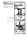
18. Remove the grease filter at bottom
of hood. Mount the hood onto the
telescopic arms using (4) M4x8 ma-
chine screws. Fig. 24. Make sure the
electrical cord is on the proper arm
with the junction box and incoming
power. Pull the safety cable from the
extension arms into the hood. Fig.
24.
19. Secure safety cables as shown in
Fig. 25.
A. Push cable through support rods
and into hood cavity.
B. Slide washer and cable clamp with
barrel nut onto cable.
Note: Barrel nut must be slightly
backed off of cable clamp and
pushed (spring compressed)
when sliding assembly onto cable.
C. Push clamp assembly all the way
to the top of the hood while push-
ing down on barrel nut. Fig. 26.
D. When assembly is all the way to
the top inside of hood, completely
tighten barrel nut.
E. Cut excess cable off.
FIG. 24
ELECTRICAL CORD
FIG. 25
M4 X 8 MM MACHINE
SCREWS - (2) PER ARM
HEX NUT
NOTE: CABLE CLAMP ASSEMBLY
INCLUDES BARREL NUT AND
HEX NUT.
BARREL NUT
EXCESS CABLE
CLAMP ASSEMBLY
FIG. 26

- 17 -
20. Drop the decorative arm covers and
canopy covers. Insert the power wire
up through the arm and into the
junction box. Fig. 27.
2 1. Make the wire connections and
install the outlet box cover with (2)
3.9x 6mm Flat Head Screws and
(2) 3.9mm lock washers. Fig. 28.
22. Install the canopy covers with (4)
M4x16 Brass Decorative Screws.
Fig. 29.
23. Slide the lower decorative arm
down onto the top of the hood and
secure with (2) 3.9 x 6mm Flat Head
Screws per arm. Fig. 30.
Go to “INSTALL GLASS PANELS”.
FIG. 27
FIG. 28
FIG. 29
M4X16
DECORATIVE
BRASS SCREW
FIG. 30
3.9 x 6 MM
FLAT HEAD
SCREWS

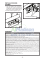
- 18 -
FOR NON-DUCTED AND DUCTED
FLUE VERSION
24. Remove the protective grille at the
top of the hood and the bottom grease
filter. Fig. 31.
25. For the ducted version install the
duct connector onto the blower inlet.
Fig. 32.
26. For non-ducted version insert the
6"-5" reduce over the blower open-
ing and duct tape into place. Fig. 32.
27. Mount the hood onto the telescop-
ic arms using (4) M4x8 machine
screws. Make sure the electrical cord
is on the proper arm with the junction
box and incoming power. Pull the
safety cable from the extension arms
into the hood. Align the duct work
with the blower opening or reducer
opening. Fig. 33.
FIG. 31
FIG. 32
DUCT CONNECTOR
6" TO 5" REDUCER
5" EXPANDABLE DUCT
non-duct applications only
FIG. 33
M4X8
MACHINE
SCREWS

- 19 -
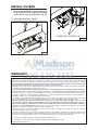
28. Secure safety cables as shown in
Fig. 34.
A. Push cable through support rods
and into hood cavity.
B. Slide washer and cable clamp with
barrel nut onto cable.
Note: Barrel nut must be slightly
backed off of cable clamp and
pushed (spring compressed)
when sliding assembly onto cable.
C. Push clamp assembly all the way
to the top of the hood while push-
ing down on barrel nut. Fig. 35.
D. When assembly is all the way to
the top inside of hood, completely
tighten barrel nut.
E. Cut excess cable off.
29. Remove the upper flue mounting
screws and drop the flues to expose
the wiring box. Make final electrical
connections. Install the outlet box
cover with (2) 3.9 x 6 mm Flat Head
Screws and (2) 3.9 mm lock wash-
ers. Fig. 36.
30. Reinstall the upper flue covers with
(4) 3.9 x 9 mm pan head screws.
Fig. 37.
31. Attached the bottom flue covers.
Fig. 38.
FIG. 34
HEX NUT
NOTE: CABLE CLAMP ASSEMBLY
INCLUDES BARREL NUT AND
HEX NUT.
BARREL NUT
Excess Cable
Clamp Assembly
FIG. 35
FIG. 37
3.9 X 9 MM PAN
HEAD SCREWS (4)
FIG. 36
FIG. 38

- 20 -
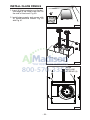
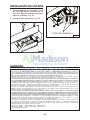
INSTALL GLASS PANELS
1. Insert (4) black protectors on the bot-
tom edge in the lower side slots on
the side of the hood. Fig. 39.
2. Install glass panels and secure with
(4) M4x8 machine screws. Fig. 40
and Fig. 41.
FIG. 39
FIG. 40
FIG. 41
M4X8
MACHINE
SCREWS (4)
La page est en cours de chargement...
La page est en cours de chargement...
La page est en cours de chargement...
La page est en cours de chargement...
La page est en cours de chargement...
La page est en cours de chargement...
La page est en cours de chargement...
La page est en cours de chargement...
La page est en cours de chargement...
La page est en cours de chargement...
La page est en cours de chargement...
La page est en cours de chargement...
La page est en cours de chargement...
La page est en cours de chargement...
La page est en cours de chargement...
La page est en cours de chargement...
La page est en cours de chargement...
La page est en cours de chargement...
La page est en cours de chargement...
La page est en cours de chargement...
La page est en cours de chargement...
La page est en cours de chargement...
La page est en cours de chargement...
La page est en cours de chargement...
La page est en cours de chargement...
La page est en cours de chargement...
La page est en cours de chargement...
La page est en cours de chargement...
La page est en cours de chargement...
La page est en cours de chargement...
La page est en cours de chargement...
La page est en cours de chargement...
La page est en cours de chargement...
La page est en cours de chargement...
La page est en cours de chargement...
La page est en cours de chargement...
La page est en cours de chargement...
La page est en cours de chargement...
La page est en cours de chargement...
La page est en cours de chargement...
La page est en cours de chargement...
La page est en cours de chargement...
La page est en cours de chargement...
La page est en cours de chargement...
La page est en cours de chargement...
La page est en cours de chargement...
La page est en cours de chargement...
La page est en cours de chargement...
La page est en cours de chargement...
La page est en cours de chargement...
La page est en cours de chargement...
La page est en cours de chargement...
-
 1
1
-
 2
2
-
 3
3
-
 4
4
-
 5
5
-
 6
6
-
 7
7
-
 8
8
-
 9
9
-
 10
10
-
 11
11
-
 12
12
-
 13
13
-
 14
14
-
 15
15
-
 16
16
-
 17
17
-
 18
18
-
 19
19
-
 20
20
-
 21
21
-
 22
22
-
 23
23
-
 24
24
-
 25
25
-
 26
26
-
 27
27
-
 28
28
-
 29
29
-
 30
30
-
 31
31
-
 32
32
-
 33
33
-
 34
34
-
 35
35
-
 36
36
-
 37
37
-
 38
38
-
 39
39
-
 40
40
-
 41
41
-
 42
42
-
 43
43
-
 44
44
-
 45
45
-
 46
46
-
 47
47
-
 48
48
-
 49
49
-
 50
50
-
 51
51
-
 52
52
-
 53
53
-
 54
54
-
 55
55
-
 56
56
-
 57
57
-
 58
58
-
 59
59
-
 60
60
-
 61
61
-
 62
62
-
 63
63
-
 64
64
-
 65
65
-
 66
66
-
 67
67
-
 68
68
-
 69
69
-
 70
70
-
 71
71
-
 72
72


Best AEIC35SB Manuel utilisateur
- Catégorie
- Hottes
- Taper
- Manuel utilisateur
dans d''autres langues
- English: Best AEIC35SB User manual
- español: Best AEIC35SB Manual de usuario
Documents connexes
-
Best IC35I90B Manuel utilisateur
-
-
-
-
-
-
Best WC35IQ90SB Manuel utilisateur
-
-
-
Best WC34IQ90SB Manuel utilisateur