Grundfos 98124695 Guide d'installation
- Catégorie
- Pompes à eau
- Taper
- Guide d'installation

GRUNDFOS INSTRUCTIONS
MAGNA1
Installation and operating instructions

2

3
Table of contents
MAGNA1
English (US)
Installation and operating instructions. . . . . . . . . . . . . . . . . . . . . . . . . . . . . . . . . . . . . . . . . . . . . . . . . . . . . . . . . . . . 4
Español (MX)
Instrucciones de instalación y operación . . . . . . . . . . . . . . . . . . . . . . . . . . . . . . . . . . . . . . . . . . . . . . . . . . . . . . . . 22
Français (CA)
Notice d'installation et de fonctionnement. . . . . . . . . . . . . . . . . . . . . . . . . . . . . . . . . . . . . . . . . . . . . . . . . . . . . . . . 40

English (US)
4
English (US) Installation and operating instructions
Original installation and operating instructions.
CONTENTS
Page
1. Limited warranty
Products manufactured by GRUNDFOS PUMPS CORPORATION
(Grundfos) are warranted to the original user only to be free of
defects in material and workmanship for a period of 24 months
from date of installation, but not more than 30 months from date
of manufacture. Grundfos' liability under this warranty shall be
limited to repairing or replacing at Grundfos' option, without
charge, F.O.B. Grundfos' factory or authorized service station,
any product of Grundfos' manufacture. Grundfos will not be liable
for any costs of removal, installation, transportation, or any other
charges which may arise in connection with a warranty claim.
Products which are sold but not manufactured by Grundfos are
subject to the warranty provided by the manufacturer of said
products and not by Grundfos' warranty. Grundfos will not be
liable for damage or wear to products caused by abnormal
operating conditions, accident, abuse, misuse, unauthorized
alteration or repair, or if the product was not installed in
accordance with Grundfos' printed installation and operating
instructions.
To obtain service under this warranty, the defective product must
be returned to the distributor or dealer of Grundfos' products from
which it was purchased together with proof of purchase and
installation date, failure date, and supporting installation data.
Unless otherwise provided, the distributor or dealer will contact
Grundfos or an authorized service station for instructions.
Any defective product to be returned to Grundfos or a service
station must be sent freight prepaid; documentation supporting
the warranty claim and/or a Return Material Authorization must
be included if so instructed.
GRUNDFOS WILL NOT BE LIABLE FOR ANY INCIDENTAL OR
CONSEQUENTIAL DAMAGES, LOSSES, OR EXPENSES
ARISING FROM INSTALLATION, USE, OR ANY OTHER
CAUSES. THERE ARE NO EXPRESS OR IMPLIED
WARRANTIES, INCLUDING MERCHANTABILITY OR FITNESS
FOR A PARTICULAR PURPOSE, WHICH EXTEND BEYOND
THOSE WARRANTIES DESCRIBED OR REFERRED TO
ABOVE.
Some jurisdictions do not allow the exclusion or limitation of
incidental or consequential damages and some jurisdictions do
not allow limit actions on how long implied warranties may last.
Therefore, the above limitations or exclusions may not apply to
you. This warranty gives you specific legal rights and you may
also have other rights which vary from jurisdiction to jurisdiction.
1. Limited warranty
4
2. Symbols used in this document
5
3. General information
5
3.1 Applications
5
3.2 Pumped liquids
5
3.3 Operating conditions
6
3.4 Frost protection
6
3.5 Insulating shells
6
3.6 Non-return valve
6
3.7 Wiring diagram
7
3.8 Nameplate
8
3.9 Tools
8
4. Mechanical installation
9
4.1 Lifting the pump
9
4.2 Installing the pump
9
4.3 Positioning
9
4.4 Control box positions
10
4.5 Changing the control box position
11
5. Electrical installation
12
5.1 Supply voltage
12
5.2 Connection to the power supply
13
6. First start-up
15
7. Settings
16
8. Control panel
16
8.1 Elements on the control panel
16
8.2 Grundfos Eye
16
8.3 Light fields indicating the pump setting
16
9. Overview of settings
17
10. Pump setting
18
11. Selection of control mode
19
12. Fault finding
20
12.1 Grundfos Eye operating status
20
12.2 Resetting of fault indications
20
13. Technical data
21
14. Disposal
21
Warning
Prior to installation, read these installation and
operating instructions. Installation and operation
must comply with local regulations and accepted
codes of good practice.
Warning
The use of this product requires experience with
and knowledge of the product.
Persons with reduced physical, sensory or
mental capabilities must not use this product,
unless they are under supervision or have been
instructed in the use of the product by a person
responsible for their safety.
Children must not use or play with this product.

5
English (US)
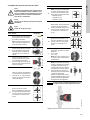
2. Symbols used in this document
3. General information
The Grundfos MAGNA1 is a complete range of circulator pumps
with integrated controller enabling adjustment of pump
performance to the actual system requirements. In many
systems, this will reduce the power consumption considerably,
reduce noise from thermostatic radiator valves and similar fittings
and improve the control of the system.
The desired head can be set on the pump control panel.
3.1 Applications
The Grundfos MAGNA1 is designed for circulating liquids in the
following systems:
• heating systems
• air-conditioning and cooling systems.
The pump can also be used in the following systems:
• ground source heat pump systems
• solar-heating systems.
3.2 Pumped liquids
The pump is suitable for thin, clean, non-aggressive and non-
explosive liquids, not containing solid particles or fibers that may
attack the pump mechanically or chemically.
In heating systems, the water should meet the requirements of
accepted standards on water quality in heating systems.
3.2.1 Glycol
The pump can be used for pumping water/glycol mixtures up to
50 %.
Example of a water/ethylene glycol mixture:
Maximum viscosity: 50 cSt ~ 50 % water / 50 % ethylene glycol
mixture at +14 °F (-10 °C).
The pump has a power-limiting function that protects against
overload.
The pumping of glycol mixtures will affect the max. curve and
reduce the performance, depending on the water/ethylene glycol
mixture and the liquid temperature.
To prevent the ethylene glycol mixture from degrading, avoid
temperatures exceeding the rated liquid temperature and
minimize the operating time at high temperatures.
It is important to clean and flush the system before the ethylene
glycol mixture is added.
To prevent corrosion or lime precipitation, check and maintain the
ethylene glycol mixture regularly. If further dilution of the supplied
ethylene glycol is required, follow the glycol supplier's
instructions.
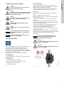
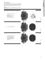
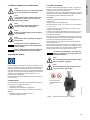
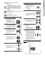
Fig. 1 Pumped liquids (flanged version)
Warning
If these safety instructions are not observed,
it may result in personal injury.
Warning
If these instructions are not observed, it may lead
to electric shock with consequent risk of serious
personal injury or death.
Warning
The surface of the product may be so hot that
it may cause burns or personal injury.
Warning
Risk of dropping objects which may cause
personal injury.
Warning
Escaping vapor involves the risk of personal
injury.
Caution
If these safety instructions are not observed,
it may result in malfunction or damage to the
equipment.
Note
Note
Notes or instructions that make the job easier
and ensure safe operation.
Note
Note
Additives with a density and/or kinematic
viscosity higher than those/that of water will
reduce the hydraulic performance.
Warning
Do not use the pump for flammable liquids, such
as diesel oil and gasoline.
Warning
Do not use the pump for aggressive liquids, such
as acids and seawater.
TM05 6385 4612
Max. 95 % RH
Enclosure Type 2

English (US)
6
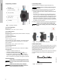
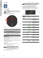
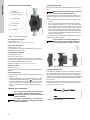
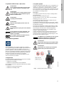
3.3 Operating conditions
Fig. 2 Operating conditions
3.3.1 Liquid temperature
See fig. 2, pos. 1.
Continuously: +14 to +230 °F (-10 to +110 °C).
3.3.2 System pressure
See fig. 2, pos. 2.
The maximum permissible system pressure is stated on the pump
nameplate. See fig. 7.
3.3.3 Ambient temperature
See fig. 2, pos. 3.
+32 to +104 °F (0 to +40 °C).
The control box is air-cooled. Therefore, it is important that the
maximum permissible ambient temperature is not exceeded
during operation.
During transport: -40 to + 158 °F (-40 to +70 °C).
3.3.4 Sound pressure level
See fig. 2, pos. 4.
The sound pressure level of the pump is lower than 43 dB(A).
3.3.5 Approvals
• Conforms to ANSI/UL Standard 778.
• Certified to CAN/CSA Standard C22.2 No. 108.
• The protective earth (ground) symbol identifies any
terminal which is intended for connection to an external
conductor for protection against electric shock in case of a
fault, or the terminal of a protective earth (ground) electrode.
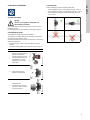
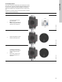
3.4 Frost protection
3.5 Insulating shells
Insulating shells are available for single-head pumps only.
The heat loss from the pump and pipework can be reduced by
insulating the pump housing and the pipework. See fig. 3.
• Insulating shbells for pumps in heating systems are supplied
with the pump.
• For pumps in air-conditioning and cooling systems (down to
14 °F (-10 °C)) it is required to apply a silicon sealant to the
internal contours of the shell in order to eliminate any air gaps
and prevent condensation between the insulation shell and
pump housing. Alternatively, the pump can also be insulated
manually in accordance with standard insulating requirements
for heating and cooling systems.
The fitting of insulation shells will increase the pump dimensions.
Fig. 3 Fitting insulating shells to the pump
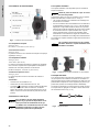
3.6 Non-return valve
If a non-return valve is fitted in the pipe system (fig. 4), it must be
ensured that the set minimum discharge pressure of the pump is
always higher than the closing pressure of the valve. This is
especially important in proportional-pressure control mode
(reduced head at low flow).
The closing pressure of a single non-return valve is accounted for
in the pump settings as the minimum head delivered is 5 ft
(1.5 m).
Fig. 4 Non-return valve
TM05 7662 1413
Caution
If the pump is not used during periods of frost,
necessary steps must be taken to prevent frost
bursts.
Note
Note
Additives with a density and/or kinematic
viscosity higher than those/that of water will
reduce the hydraulic performance.
Min./Max.
+14 °F to 230 °F
(-10 °C to +110 °C)
175 psi (12 bar)
1
2
3
4
+32 to +104 °F
(0 to +40 °C)
< 43 dB(A)
Note
Note
Limit the heat loss from the pump housing and
pipework.
Note
Note
Pumps are factory-fitted with insulating shells.
Remove the insulating shells before installing the
pump.
TM05 5512 3812
TM05 3055 0912

7
English (US)
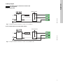
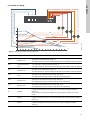
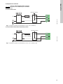
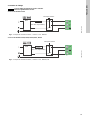
3.7 Wiring diagram
3.7.1 For models 32-XX
Fig. 5 Example of terminal connection, 1 x 230 V ± 10 %, 50/60 Hz
3.7.2 For models 40-XX, 50-XX, 65-XX, 80-XX, 100-XX
Fig. 6 Example of terminal connection, 1 x 230 V ± 10 %, 50/60 Hz, PE
Caution
All cables must be connected in accordance with
local regulations.
TM06 1256 2214
External switch
Fuse
(min. 10 A, time lag)
GFCI
TM03 2397 0312
External switch
Fuse
(min. 10 A, time lag)
GFCI

English (US)
8
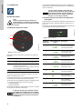
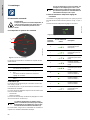
3.8 Nameplate
The pump nameplate provides the following information:
Fig. 7 Example of nameplate
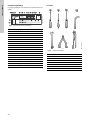
3.9 Tools
Fig. 8 Recommended tools
TM05 6381 1713
Pos. Description
1 Product name
2 Model
3 Production code (year and week)
4 Serial number
5 Product number
6 Enclosure type
7 Energy Efficiency Index (EEI)
8 Part (according to EEI)
9 TF-class
10 Minimum current [A]
11 Maximum current [A]
12 Minimum power [W]
13 Maximum power [W]
14 Maximum pressure
15 Voltage [V] and frequency [Hz]
16 QR (Quick Response) code
17 Approvals (nameplate)
18 Assembled in USA
RISQUE DE CHOC ELECTRIQUE. HORS DES EQUIPEMENT AVANT ENLEVEMENT DE LA COUVERTURE ET D’ENTRENTIEN. POUR
LE RECCORDEMENT D’ALIMENTATION, EMPLOYEZ DES FILS QUI RESISTENT AU MOINS A 90 °C UTILISEZ UNIQUEMENT DES
CONDUCTEURS DE CUIVRE. POUR RE’DUIRE LES RISQUES DE CHOC E’LECTRIQUE, CONSULTES LE MANUEL D’INSTRUCTIONS
POUR UNE INSTALLATION CORRECTE. EMPLOYER UNIQUEMENT A L’INTERIEUR.
TYPE 2
BOITIER DE TYPE 2
THERMALLY PROTECTED
Nonsubmersible Pump
RISK OF ELECTRIC SHOCK. DE-ENERGIZE EQUIPMENT BEFORE REMOVAL OF COVER & SERVICING. FOR SUPPLY
CONNECTION USE COPPER WIRE SUITABLE FOR 90 °C OR EQUIVALENT. THIS PUMP HAS NOT BEEN INVESTIGATED FOR USE
IN SWIMMING POOL OR MARINE AREAS. TO REDUCE THE RISK OF ELECTRIC SHOCK, SEE INSTRUCTION MANUAL FOR
PROPER INSTALLATION; ACCEPTABLE FOR INDOOR USE ONLY.
PSI
For use with maximum 230° F water
Contains FCC ID: OG3-RADIOM01-2G4
TM05 6472 4712
Pos. Tool Size
1 Screwdriver, straight slot 1.2 x 8.0 mm
2 Screwdriver, straight slot 0.6 x 3.5 mm
3 Screwdriver, torx bit TX20
4 Hexagon key 5.0 mm
5 Open-end wrench Depending on size
6 Wire cutter
7 Pipe wrench
1.2 x 8.0 TX200.6 x 3.5 5.0
123 4
56 7

9
English (US)
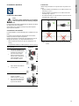
4. Mechanical installation
4.1 Lifting the pump
Always lift directly on the pump head or the cooling fins when
handling the pump.
For large pumps, it may be necessary to use lifting equipment.
4.2 Installing the pump
The MAGNA1 is designed for indoor installation.
The pump may be suspended direct in the pipes, provided that
the pipework can support the pump.
To ensure adequate cooling of motor and electronics, observe the
following requirements:
• Position the pump in such a way that sufficient cooling is
ensured.
• The ambient temperature must not exceed +104 °F (+40 °C).
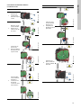
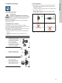
4.3 Positioning
Always install the pump with horizontal motor shaft.
• Pump installed correctly in a vertical pipe. See fig. 9, pos. A.
• Pump installed correctly in a horizontal pipe. See fig. 9, pos. B.
• Do not install the pump with vertical motor shaft. See fig. 9,
pos. C and D.
Fig. 9 Pump installed with horizontal motor shaft
Warning
Observe local regulations setting limits for
manual lifting or handling.
Step Action Illustration
1
Arrows on the pump housing
indicate the liquid flow
direction through the pump.
The liquid flow direction can
be horizontal or vertical,
depending on the control
box position.
TM05 5513 3812
2
Mount the pump with
gaskets in the pipework.
TM05 5515 3812
3
Flanged version:
Fit bolts and nuts. Use the
right size of bolts according
to system pressure.
TM05 5516 3816
TM05 5518 3812
AB
CD

English (US)
10
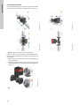
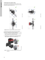
4.4 Control box positions
To ensure adequate cooling, the control box must be in horizontal
position with the Grundfos logo in vertical position. See fig. 10.
Fig. 10 Pump with control box in horizontal position
If the pump head is removed before the pump is installed in the
pipework, pay special attention when fitting the pump head to the
pump housing:
1. Gently lower the pump head with rotor shaft and impeller into
the pump housing.
2. Make sure that the contact face of the pump housing and that
of the pump head are in contact before the clamp is tightened.
See fig. 11.
Fig. 11 Fitting the pump head to the pump housing
TM05 5519 3812
TM05 5520 3812
TM05 5521 3812
TM05 5522 3812
TM05 5837 4112

11
English (US)
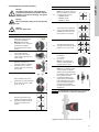
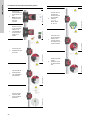
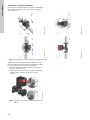
4.5 Changing the control box position
Fig. 12 Insulation of pump housing and pipework
Warning
The warning symbol on the clamp holding the
pump head and pump housing together indicates
that there is a risk of personal injury. See specific
warnings below.
Warning
When loosening the clamp, do not drop the pump
head.
Warning
Risk of escaping vapor.
Step Action Illustration
1
Loosen the screw in the clamp
holding the pump head and
pump housing together.
Warning: If the screw is
loosened too much, the pump
head will be completely
disconnected from the pump
housing.
TM05 2867 0612
2
Carefully rotate the pump head
to the desired position.
If the pump head is stuck,
loosen it with a light blow of a
rubber mallet.
TM05 5526 3812
3
Place the control box in
horizontal position so that the
Grundfos logo is in vertical
position. The motor shaft must
be horizontal.
TM05 5527 3812
4
Due to the drain hole in the
stator housing, position the gap
of the clamp as shown in step
4a, 4b, 4c, or 4d.
TM05 2870 0612
4a
Flanged single-head pump.
Position the clamp so that the
gap points towards the arrow.
It can be in position 3 or 9
o'clock.
TM05 2918 0612 - TM05 2871 0612
4b
Flanged single-head pump.
Note: The gap of the clamp can
also be in position 6 o'clock for
the following pump sizes:
•MAGNA1 65-XX
•MAGNA1 80-XX
• MAGNA1 100-XX.
TM05 2899 1912
4c
Twin-head pump. Position the
clamps so that the gaps point
towards the arrows. They can
be in position 3 or 9 o'clock.
TM05 2917 0612 - TM05 2873 0612
4d
Threaded single-head pump.
The gap of the clamp can be in
position 3, 6, 9 or 12 o'clock.
TM05 5528 3812
5
Fit and tighten the screw holding
the clamp to:
6 ± 0.7 ft-lbs
(8 ± 1 Nm).
Note: Do not retighten the
screw if condensed water is
dripping from the clamp.
TM05 2872 0612
6
Fit the insulating shells.
Note: For air conditioning and
cooling systems, a silicone
sealant must be applied inside
the insulation shell to eliminate
all air gaps and prevent
condensation between the
pump housing and insulation
shell. Alternatively, the pump
may be insulated manually in
accordance with standard
insulation practices for cooling
applications.
TM05 5529 3812
Caution
If insulating the pump manually, do not insulate
the control box or cover the control panel.
TM05 5549 3812
Step Action Illustration

English (US)
12
5. Electrical installation
Carry out the electrical connection and protection according to
local regulations.
Check that the supply voltage and frequency correspond to the
values stated on the nameplate.
• If rigid conduit is to be used, the hub must be connected to the
conduit system before it is connected to the terminal box of the
pump.
• The pump must be connected to an external mains switch.
• The pump requires no external motor protection.
• The motor incorporates thermal protection against slow
overloading and blocking (IEC 34-11: TP 211).
• When switched on via the power supply, the pump will start
pumping after approximately 5 seconds.
5.1 Supply voltage
Check nameplate voltage.
1 x 115 V ± 10 %, 50/60 Hz, PE.
1 x 208-230 V ± 10 %, 50/60 Hz, PE.
See pump nameplate for rated supply voltage
The voltage tolerances are intended for mains voltage variations.
They should not be used for running pumps at other voltages than
those stated on the nameplate.
Warning
Switch off the power supply before making
connections.
Warning
Never make any connections in the pump control
box unless the power supply has been switched
off for at least 5 minutes.
Warning
The pump must be connected to an external
mains switch with a contact separation of at least
1/8 inch (3 mm) in each pole.
The ground terminal of the pump must be earth
ground.
Grounding or neutralization can be used for
protection against indirect contact.
If the pump is connected to an electric
installation where a Ground Fault Circuit
Interrupter (GFCI) is used as additional
protection, this circuit interrupter must trip out
when ground fault currents with DC content
(pulsating DC) occur.
Note
Note
The number of starts and stops via the power
supply must not exceed four times per hour.

13
English (US)
5.2 Connection to the power supply
5.2.1 Models 32-XX
Step Action Illustration
1
Remove the front
cover from the
control box.
TM06 1259 2014
2
Locate the power
supply plug inside
the control box.
TM06 1260 2014
3
Connect the
conduit and feed
the power cable
through the
control box.
TM06 1261 2014TM06 1262 2014
4
Strip the wires as
illustrated and
connect the
conductors to the
power supply
plug.
TM06 1263 2014TM06 1264 2014
L (L1)
N (L2)
0.28 in. (7 mm)
0.79 in. (20 mm)
0.28 in. (7 mm)
1.0 in. (25 mm)
Min.
ĭ0.28 in. (7 mm)
MaxĭPP
5
Insert the supply
plug into the
power receptacle
on the PCB.
TM06 1265 2014TM06 1266 2014
6
Tighten the
conduit and refit
the front cover.
TM06 1267 2014TM06 1268 2014
Step Action Illustration

English (US)
14
5.2.2 Models 40-XX, 50-XX, 65-XX, 80-XX, 100-XX
Step Action Illustration
1
Remove the front
cover from the
control box.
Note: Do not
remove the
screws from the
cover.
TM05 5530 3812
2
Locate the power
supply plug and
conduit adapter in
the box supplied
with the pump.
TM05 5531 3812
3
Connect the
conduit adapter to
the control box.
TM05 5532 3812
4
Pull the power
supply cable
through the
conduit adapter.
TM05 5533 3812
5
Strip the cable
conductors as
illustrated.
TM05 5534 3812
6
Connect the cable
conductors to the
power supply
plug.
L - L or L1
Ground - Ground
N - N or L2
TM05 5535 3812
7
Insert the power
supply plug into
the male plug in
the pump control
box.
TM05 5536 3812
8
Tighten the
conduit adapter.
Refit the front
cover.
TM05 5537 3812
Step Action Illustration

15
English (US)
6. First start-up
Do not start the pump until the system has been filled with liquid
and vented. Furthermore, the required minimum inlet pressure
must be available at the pump inlet. See section 13. Technical
data.
The system cannot be vented through the pump. The pump is
self-venting.
Step Action Illustration
1
Switch on the power supply
to the pump.
Note: When switched on, the
pump will start after
approximately 5 seconds.
TM05 5550 3812
2 Control panel at first start-up.
TM05 5551 3812
3
The pump has been factory-
set to the intermediate
proportional-pressure curve.
Select the control mode
according to the system
application.
TM05 5551 3812

English (US)
16
7. Settings
8. Control panel
8.1 Elements on the control panel
Fig. 13 Control panel
The control panel on the pump comprises the following elements:
8.2 Grundfos Eye
The Grundfos Eye is on when the power supply has been
switched on. See fig. 13, pos. 1.
The Grundfos Eye is an indicator light providing information about
the actual pump status.
The indicator light will flash in different sequences and provide
information about the following:
• power on/off
• pump alarms.
The function of the Grundfos Eye is described in section
12.1 Grundfos Eye operating status.
If a fault is indicated, correct the fault and reset the pump by
switching the power supply off and on.
8.3 Light fields indicating the pump setting
The pump has nine optional performance settings which can be
selected with the push-button. See fig. 13, pos. 2 and 3.
The pump setting is indicated by nine light fields in the display.
Fig. 14 Factory setting
Warning
At high liquid temperatures, the pump housing
may be very hot. In that case, only touch the
control panel.
TM05 5552 3812
Pos. Description
1
Grundfos Eye operating status.
See section 8.2 Grundfos Eye.
2
Eight light fields indicating the pump setting.
See section 8.3 Light fields indicating the pump
setting.
3 Push-button for selection of pump setting.
Note
Note
Faults preventing the pump from operating
properly (for example blocked rotor) are
indicated by the Grundfos Eye. See section
12.1 Grundfos Eye operating status.
1
2
3
Note
Note
If the pump impeller is rotated, for example when
filling the pump with water, sufficient energy can
be generated to light up the control panel even if
the power supply has been switched off.
TM05 5553 3812
Number of
button
presses
Active light fields Description
0
Intermediate
proportional-pressure
curve, referred to as PP2
1
Highest proportional-
pressure curve, referred
to as PP3
2
Lowest constant-
pressure curve, referred
to as CP1
3
Intermediate constant-
pressure curve, referred
to as CP2
4
Highest constant-
pressure curve, referred
to as CP3
5
Constant curve/constant
speed III
6
Constant curve/constant
speed II
7
Constant curve/constant
speed I
8
Lowest proportional-
pressure curve, referred
to as PP1

17
English (US)
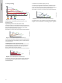
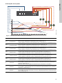
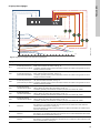
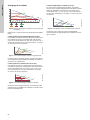
9. Overview of settings
Fig. 15 Pump setting in relation to pump performance
TM05 2777 0512
III
II
I
H
PP3
CP3
CP2
PP1
CP1
PP2
Q
Setting Pump curve Function
PP1
Lowest proportional-
pressure curve
The duty point of the pump will move up or down on the lowest proportional-pressure curve,
depending on the heat demand. See fig. 15.
The head (pressure) is reduced at falling heat demand and increased at rising heat demand.
PP2
Intermediate
proportional-pressure
curve
The duty point of the pump will move up or down on the intermediate proportional-pressure
curve, depending on the heat demand. See fig. 15.
The head (pressure) is reduced at falling heat demand and increased at rising heat demand.
PP3
Highest proportional-
pressure curve
The duty point of the pump will move up or down on the highest proportional-pressure curve,
depending on the heat demand. See fig. 15.
The head (pressure) is reduced at falling heat demand and increased at rising heat demand.
CP1
Lowest constant-pressure
curve
The duty point of the pump will move out or in on the lowest constant-pressure curve,
depending on the heat demand in the system. See fig. 15.
The head (pressure) is kept constant, irrespective of the heat demand.
CP2
Intermediate constant-
pressure curve
The duty point of the pump will move out or in on the intermediate constant-pressure curve,
depending on the heat demand in the system. See fig. 15.
The head (pressure) is kept constant, irrespective of the heat demand.
CP3
Highest constant-
pressure curve
The duty point of the pump will move out or in on the highest constant-pressure curve,
depending on the heat demand in the system. See fig. 15.
The head (pressure) is kept constant, irrespective of the heat demand.
III Speed III
The pump runs on a constant curve which means that it runs at a constant speed.
In speed III, the pump is set to run on the max. curve under all operating conditions.
See fig. 15.
Quick venting of the pump can be obtained by setting the pump to speed III for a short
period.
II Speed II
The pump runs on a constant curve which means that it runs at a constant speed.
In speed II, the pump is set to run on the intermediate curve under all operating conditions.
See fig. 15.
I Speed I
The pump runs on a constant curve which means that it runs at a constant speed.
In speed I, the pump is set to run on the min. curve under all operating conditions.
See fig. 15.

English (US)
18
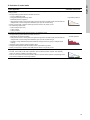
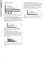
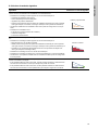
10. Pump setting
Fig. 16 Selection of pump setting for system type
Factory setting: Intermediate proportional-pressure curve,
referred to as PP2.
Proportional-pressure curve (PP1, PP2 or PP3)
Proportional-pressure control adjusts the pump performance to
the actual heat demand in the system, but the pump performance
follows the selected performance curve, PP1, PP2 or PP3.
See fig. 17 where PP2 has been selected.
See section 11. Selection of control mode for further information.
Fig. 17 Three proportional-pressure curves/settings
The selection of the right proportional-pressure setting depends
on the characteristics of the heating system in question and the
actual heat demand.
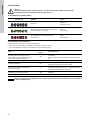
Constant-pressure curve (CP1, CP2 or CP3)
Constant-pressure control adjusts the pump performance to the
actual heat demand in the system, but the pump performance
follows the selected performance curve, CP1, CP2 or CP3.
See fig. 18 where CP1 has been selected.
See section 11. Selection of control mode for further information.
Fig. 18 Three constant-pressure curves/settings
The selection of the right constant-pressure setting depends on
the characteristics of the heating system in question and the
actual heat demand.
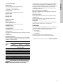
Constant curve/constant speed (I, II or III)
At constant-curve/constant-speed operation, the pump runs at a
constant speed, independent of the actual flow demand in the
system. The pump performance follows the selected performance
curve, I, II or III. See fig. 19 where II has been selected.
See section 11. Selection of control mode for further information.
Fig. 19 Three constant-curve/constant-speed settings
The selection of the right constant-curve/constant-speed setting
depends on the characteristics of the heating system in question.
TM05 5554 3812
TM05 5555 3812
TM05 5556 3812
Q
H
PP3
PP2
PP1
Q
H
Q
H
CP3
CP2
CP1
TM05 5557 3812
Q
H

19
English (US)
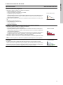
11. Selection of control mode
System application Select this control mode
In systems with relatively large pressure losses in the distribution pipes and in air-conditioning and
cooling systems.
• Two-pipe heating systems with thermostatic valves and
– very long distribution pipes
– strongly throttled pipe balancing valves
– differential-pressure regulators
– large pressure losses in those parts of the system through which the total quantity of water flows (for
example boiler, heat exchanger and distribution pipe up to the first branching).
• Primary circuit pumps in systems with large pressure losses in the primary circuit.
• Air-conditioning systems with
– heat exchangers (fan coils)
– cooling ceilings
– cooling surfaces.
Proportional pressure
In systems with relatively small pressure losses in the distribution pipes.
• Two-pipe heating systems with thermostatic valves and
– dimensioned for natural circulation
– small pressure losses in those parts of the system through which the total quantity of water flows (for
example boiler, heat exchanger and distribution pipe up to the first branching) or
– modified to a high differential temperature between flow pipe and return pipe (for example district
heating).
• Underfloor heating systems with thermostatic valves.
• One-pipe heating systems with thermostatic valves or pipe balancing valves.
• Primary circuit pumps in systems with small pressure losses in the primary circuit.
Constant pressure
The pump can also be set to operate according to the max. or min. curve, like an uncontrolled pump:
• The max. curve mode can be used in periods in which a maximum flow is required. This operating
mode is for instance suitable for hot-water priority.
• The min. curve mode can be used in periods in which a minimum flow is required. This operating mode
is for instance suitable for manual night setback.
Constant curve
Q
H
Q
H
Q
H

English (US)
20
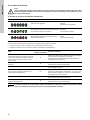
12. Fault finding
12.1 Grundfos Eye operating status
12.2 Resetting of fault indications
A fault indication can be reset in one of the following ways:
• When the fault cause has been eliminated, the pump will revert to normal duty.
• If the fault disappears by itself, the fault indication will automatically be reset.
Warning
Before dismantling the pump, drain the system or close the isolating valve on either side of the pump.
The pumped liquid may be scalding hot and under high pressure.
Grundfos Eye Indication Cause
No lights on.
Power off.
Pump not running.
Two opposite green indicator lights running in the
direction of rotation of the pump.
Power on.
Pump running.
Two opposite red indicator lights flashing
simultaneously.
Alarm.
Pump stopped.
Fault
Automatic reset and
restart?
Corrective actions
Other pumps or sources force flow through
the pump even if the pump is stopped.
There will be light in the display even if the
power supply has been switched off.
Yes
Check the system for defective non-return valves and replace,
if necessary.
Check the system for correct position of non-return valves,
etc.
Supply voltage to the pump too low. Yes Check that the power supply is within the specified range.
The pump is blocked. No
Dismantle the pump, and remove any foreign matter or
impurities preventing the pump from rotating.
No water at the pump inlet or the water
contains too much air.
No
Prime and vent the pump before a new start-up. Check that
the pump is operating correctly. If not, replace the pump, or
call GRUNDFOS SERVICE for assistance.
Internal fault in the pump electronics. Yes
Replace the pump, or call GRUNDFOS SERVICE for
assistance.
Supply voltage to the pump too high. Yes Check that the power supply is within the specified range.
Caution
If the power supply cable is damaged, it must be replaced by the manufacturer, the manufacturer's service partner or
a similarly qualified person.
La page est en cours de chargement...
La page est en cours de chargement...
La page est en cours de chargement...
La page est en cours de chargement...
La page est en cours de chargement...
La page est en cours de chargement...
La page est en cours de chargement...
La page est en cours de chargement...
La page est en cours de chargement...
La page est en cours de chargement...
La page est en cours de chargement...
La page est en cours de chargement...
La page est en cours de chargement...
La page est en cours de chargement...
La page est en cours de chargement...
La page est en cours de chargement...
La page est en cours de chargement...
La page est en cours de chargement...
La page est en cours de chargement...
La page est en cours de chargement...
La page est en cours de chargement...
La page est en cours de chargement...
La page est en cours de chargement...
La page est en cours de chargement...
La page est en cours de chargement...
La page est en cours de chargement...
La page est en cours de chargement...
La page est en cours de chargement...
La page est en cours de chargement...
La page est en cours de chargement...
La page est en cours de chargement...
La page est en cours de chargement...
La page est en cours de chargement...
La page est en cours de chargement...
La page est en cours de chargement...
La page est en cours de chargement...
La page est en cours de chargement...
La page est en cours de chargement...
La page est en cours de chargement...
La page est en cours de chargement...
-
 1
1
-
 2
2
-
 3
3
-
 4
4
-
 5
5
-
 6
6
-
 7
7
-
 8
8
-
 9
9
-
 10
10
-
 11
11
-
 12
12
-
 13
13
-
 14
14
-
 15
15
-
 16
16
-
 17
17
-
 18
18
-
 19
19
-
 20
20
-
 21
21
-
 22
22
-
 23
23
-
 24
24
-
 25
25
-
 26
26
-
 27
27
-
 28
28
-
 29
29
-
 30
30
-
 31
31
-
 32
32
-
 33
33
-
 34
34
-
 35
35
-
 36
36
-
 37
37
-
 38
38
-
 39
39
-
 40
40
-
 41
41
-
 42
42
-
 43
43
-
 44
44
-
 45
45
-
 46
46
-
 47
47
-
 48
48
-
 49
49
-
 50
50
-
 51
51
-
 52
52
-
 53
53
-
 54
54
-
 55
55
-
 56
56
-
 57
57
-
 58
58
-
 59
59
-
 60
60


Grundfos 98124695 Guide d'installation
- Catégorie
- Pompes à eau
- Taper
- Guide d'installation
dans d''autres langues
- English: Grundfos 98124695 Installation guide
- español: Grundfos 98124695 Guía de instalación
Documents connexes
-
Grundfos MAGNA3 25-100 (N) Installation And Operating Instructions Manual
-
Aerco Lead-Free Constant Speed Pump Kit Instructions Manual
-
-
-
-
Grundfos 59896343 Mode d'emploi
-
-
-
Grundfos Comfort System Manuel utilisateur
-