Sharp PN-465E Mode d'emploi
- Catégorie
- Téléviseurs
- Taper
- Mode d'emploi
Ce manuel convient également à

PN-465E
ENGLISH DEUTSCH FRANÇAIS
汉语
РУССКИЙ
LCD MONITOR
LCD FARBMONITOR
MONITEUR LCD
ЖК МОНИТОР
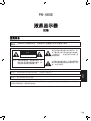
液晶显示器
OPERATION MANUAL
BEDIENUNGSANLEITUNG
MODE D’EMPLOI
РУКОВОДСТВО ПО ЭКСПЛУАТАЦИИ
使用说明书
ENGLISH ...... E1
DEUTSCH ..... D1
FRANÇAIS .... F1
РУССКИЙ ..... Р1
汉语 ............... C1

Authorised representative responsible for the European Union Community Market
Autorisierter Repräsentant in der Europäischen Union
Représentant autorisé pour le marché de la communauté européenne
SHARP ELECTRONICS (Europe) GmbH
Sonninstraße 3, D-20097 Hamburg

ENGLISH
1
E
IMPORTANT INFORMATION
PN-465E
LCD MONITOR
ENGLISH
WARNING:
TO REDUCE THE RISK OF FIRE OR ELECTRIC SHOCK, DO NOT
EXPOSE THIS PRODUCT TO RAIN OR MOISTURE.
RISK OF ELECTRIC
SHOCK
DO NOT OPEN
CAUTION
CAUTION: TO REDUCE THE RISK OF ELECTRIC
SHOCK, DO NOT REMOVE COVER.
NO USER-SERVICEABLE PARTS
INSIDE.
REFER SERVICING TO QUALIFIED
SERVICE PERSONNEL.
The lightning flash with arrowhead symbol, within
an equilateral triangle, is intended to alert the
user to the presence of uninsulated “dangerous
voltage” within the product’s enclosure that may
be of sufficient magnitude to constitute a risk of
electric shock to persons.
The exclamation point within a triangle is
intended to alert the user to the presence of
important operating and maintenance (servicing)
instructions in the literature accompanying the
product.
CAUTION:
The AC outlet shall be installed near the equipment and shall be easily accessible.
FOR CUSTOMERS IN U.K.
IMPORTANT
The wires in this mains lead are coloured in accordance with the following code:
GREEN-AND-YELLOW : Earth
BLUE : Neutral
BROWN : Live
As the colours of the wires in the mains lead of this apparatus may not correspond with the coloured markings identifying the
terminals in your plug proceed as follows:
• The wire which is coloured GREEN-AND-YELLOW must be connected to the terminal in the plug which is marked by the
letter E or by the safety earth or coloured green or green-and-yellow.
• The wire which is coloured BLUE must be connected to the terminal which is marked with the letter
N or coloured black.
• The wire which is coloured BROWN must be connected to the terminal which is marked with the letter
L or coloured red.
Ensure that your equipment is connected correctly. If you are in any doubt consult a qualified electrician.
“WARNING: THIS APPARATUS MUST BE EARTHED.”

2
E
CAUTION:
Use the supplied power cord as it is.
IMPORTANT INFORMATION (Continued)
This product utilises fluorescent tubes containing a small amount of mercury.
Disposal of these materials may be regulated due to environmental considerations. For disposal or recycling information,
please contact your local authorities.
A. Information on Disposal for Users (private households)
1. In the European Union
Attention: If you want to dispose of this equipment, please do not use the ordinary dustbin!
Used electrical and electronic equipment must be treated separately and in accordance with legislation that requires proper
treatment, recovery and recycling of used electrical and electronic equipment.
Following the implementation by member states, private households within the EU states may return their used electrical and
electronic equipment to designated collection facilities free of charge*. In some countries* your local retailer may also take
back your old product free of charge if you purchase a similar new one.
*) Please contact your local authority for further details.
If your used electrical or electronic equipment has batteries or accumulators, please dispose of these separately beforehand
according to local requirements.
By disposing of this product correctly you will help ensure that the waste undergoes the necessary treatment, recovery and
recycling and thus prevent potential negative effects on the environment and human health which could otherwise arise due
to inappropriate waste handling.
2. In other Countries outside the EU
If you wish to discard this product, please contact your local authorities and ask for the correct method of disposal.
For Switzerland: Used electrical or electronic equipment can be returned free of charge to the dealer, even if you don’t
purchase a new product. Further collection facilities are listed on the homepage of www.swico.ch or www.sens.ch.
B. Information on Disposal for Business Users
1. In the European Union
If the product is used for business purposes and you want to discard it:
Please contact your SHARP dealer who will inform you about the take-back of the product. You might be charged for the
costs arising from take-back and recycling. Small products (and small amounts) might be taken back by your local collection
facilities.
For Spain: Please contact the established collection system or your local authority for take-back of your used products.
2. In other Countries outside the EU
If you wish to discard of this product, please contact your local authorities and ask for the correct method of disposal.
Attention: Your product is marked with this symbol. It means that used electrical and electronic products
should not be mixed with general household waste. There is a separate collection system for these products.

ENGLISH
3
E
Thank you for your purchase of a SHARP LCD product. To ensure safety and many years of trouble-free operation of your
product, please read the Safety Precautions carefully before using this product.
SAFETY PRECAUTIONS
Electricity is used to perform many useful functions, but it can also cause personal injuries and property damage if improperly
handled. This product has been engineered and manufactured with the highest priority on safety. However, improper use can
result in electric shock and/or fire. In order to prevent potential danger, please observe the following instructions when installing,
operating and cleaning the product. To ensure your safety and prolong the service life of your LCD product, please read the
following precautions carefully before using the product.
1. Read instructions — All operating instructions must be read and understood before the product is operated.
2. Keep this manual in a safe place — These safety and operating instructions must be kept in a safe place for future
reference.
3. Observe warnings — All warnings on the product and in the instructions must be observed closely.
4. Follow instructions — All operating instructions must be followed.
5. Cleaning — Unplug the power cord from the AC outlet before cleaning the product. Use a dry cloth to clean the product. Do
not use liquid cleaners or aerosol cleaners.
6. Attachments — Do not use attachments not recommended by the manufacturer. Use of inadequate attachments can result
in accidents.
7. Water and moisture — Do not use the product near water.
8. Ventilation — The vents and other openings in the cabinet are designed for ventilation.
Do not cover or block these vents and openings since insufficient ventilation can cause overheating and/or shorten the life
of the product. Do not place the product on a sofa, rug or other similar surface, since they can block ventilation openings.
Do not place the product in an enclosed place such as a bookcase or rack, unless proper ventilation is provided or the
manufacturer’s instructions are followed.
9. Power cord protection — The power cords must be routed properly to prevent people from stepping on them or objects from
resting on them.
10. The LCD panel used in this product is made of glass. Therefore, it can break when the product is dropped or applied with
impact. Be careful not to be injured by broken glass pieces in case the LCD panel breaks.
11. Overloading — Do not overload AC outlets or extension cords. Overloading can cause fire or electric shock.
12. Entering of objects and liquids — Never insert an object into the product through vents or openings. High voltage flows in
the product, and inserting an object can cause electric shock and/or short internal parts.
For the same reason, do not spill water or liquid on the product.
13. Servicing — Do not attempt to service the product yourself. Removing covers can expose you to high voltage and other
dangerous conditions. Request a qualified service person to perform servicing.
14. Repair — If any of the following conditions occurs, unplug the power cord from the AC outlet, and request a qualified service
person to perform repairs.
a. When the power cord or plug is damaged.
b. When a liquid was spilled on the product or when objects have fallen into the product.
c. When the product has been exposed to rain or water.
d. When the product does not operate properly as described in the operating instructions.
Do not touch the controls other than those described in the operating instructions. Improper adjustment of controls
not described in the instructions can cause damage, which often requires extensive adjustment work by a qualified
technician.
e. When the product has been dropped or damaged.
f. When the product displays an abnormal condition. Any noticeable abnormality in the product indicates that the product
needs servicing.
DEAR SHARP CUSTOMER

4
E
15. Replacement parts — In case the product needs replacement parts, make sure that the service person uses replacement
parts specified by the manufacturer, or those with the same characteristics and performance as the original parts. Use of
unauthorised parts can result in fire, electric shock and/or other danger.
16. Safety checks — Upon completion of service or repair work, request the service technician to
perform safety checks to ensure that the product is in proper operating condition.
17. Wall mounting — When mounting the product on a wall, be sure to install the product according to the method
recommended by the manufacturer.
18. Heat sources — Keep the product away from heat sources such as radiators, heaters, stoves and other heat-generating
products (including amplifiers).
19. Usage of the monitor must not be accompanied by fatal risks or dangers that, could lead directly to death, personal injury,
severe physical damage or other loss, including nuclear reaction control in nuclear facility, medical life support system, and
missile launch control in a weapon system.
SAFETY PRECAUTIONS (Continued)
WARNING:
This is a class A product. In a domestic environment this product may cause radio interference in which case the user may
be required to take adequate counter measures.

ENGLISH
5
E
- The TFT colour LCD panel used in this monitor is made with
the application of high precision technology. However, there
may be minute points on the screen where pixels never light
or are permanently lit. Also, if the screen is viewed from an
acute angle there may be uneven colours or brightness.
Please note that these are not malfunctions but common
phenomena of LCDs and will not affect the performance of
the monitor.
- Do not display a still picture for a long period, as this could
cause a residual image.
- Never rub or tap the monitor with hard objects.
- Please understand that Sharp Corporation bears no
responsibility for errors made during use by the customer or
a third party, nor for any other malfunctions or damage to this
product arising during use, except where indemnity liability is
recognised under law.
- This monitor and its accessories may be upgraded without
advance notice.
- Do not use the monitor where there is a lot of dust, where
humidity is high, or where the monitor may come into contact
with oil or steam, as this could lead to fire.
- Ensure that the monitor does not come into contact with
water or other fluids. Ensure that no objects such as paper
clips or pins enter the monitor as this could lead to fire or
electric shock.
- Do not place the monitor on top of unstable objects or in
unsafe places. Do not allow the monitor to receive strong
shocks or to strongly vibrate. Causing the monitor to fall or
topple over may damage it.
- Do not use the monitor near heating equipment or in places
where there is likelihood of high temperature, as this may
lead to generation of excessive heat and outbreak of fire.
The Power Cord
- Do not damage the power cord nor place heavy objects on
it, stretch it or over bend it. Also, do not add extension cords.
Damage to the cord may result in fire or electric shock.
- Use only the power cord supplied with the monitor.
- Insert the power plug directly into the AC outlet.
Adding an extension cord may lead to fire as a result of
overheating.
- Do not remove or insert the power plug with wet hands.
Doing so could result in electric shock.
- Unplug the power cord if it is not used for a long time.
- Do not attempt to repair the power cord if it is broken
or malfunctioning. Refer the servicing to the service
representative.
Manual Scope
- Microsoft and Windows are registered trademarks of
Microsoft Corporation.
- This product comes with RICOH Bitmap Fonts produced and
sold by RICOH COMPANY, LTD.
- All other brand and product names are trademarks or
registered trademarks of their respective holders.
- Language of OSD menu used in this manual is English by
way of example.
- Illustrations in this manual may not exactly represent the
actual product or display.
- This manual assumes use in horizontal orientation, except
where specifically noted.
Fluorescent Tubes
● The fluorescent tubes in this product have a limited lifetime.
* If the screen gets dark, flashes, or does not turn on,
change the fluorescent tubes with new exclusive ones.
* For more information, please contact your product
dealer.
● Because of the property of fluorescent tubes, the screen
may flash during the initial period of use. If this happens,
please turn off the main power switch of the monitor and
turn on again to confirm operation.
TIPS AND SAFETY INSTRUCTIONS

6
E
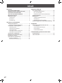
Contents
Introduction
IMPORTANT INFORMATION ............................................1
DEAR SHARP CUSTOMER ..............................................
3
SAFETY PRECAUTIONS ..................................................
3
TIPS AND SAFETY INSTRUCTIONS ...............................
5
Supplied Accessories ......................................................
7
Part Names .......................................................................7
Front view .....................................................................7
Rear view .....................................................................8
Remote control unit ......................................................8
Connection and Installation
How to Install the Monitor ...............................................9
Mounting precautions ...................................................9
Connecting Peripheral Equipment ...............................10
Connection with a PC .................................................10
Connection with AV equipment ..................................
10
Other terminals ...........................................................11
Connecting external speakers ....................................11
Connecting multiple monitors .....................................11
Connecting the Power Cord .........................................12
Mounting the Temporary Stands ..................................
12
Binding Cables ...............................................................13
Preparing the Remote Control Unit ..............................13
Installing the batteries ................................................13
Remote control operation range .................................13
Basic Operation
Turning Power On/Off ....................................................14
Turning on the main power ........................................
14
Turning power on/off ..................................................
14
Disabling power on/off operations ..............................14
Basic Operation .............................................................15
Menu Items .....................................................................17
Displaying the menu screen .......................................17
Menu item details .......................................................18
Adjustments for PC screen display ............................23
Initialisation (Reset)/
Functional Restriction Setting ..................................24
PC Operation
Controlling the Monitor with a PC ................................25
PC connection ............................................................25
Communication conditions .........................................25
Communication procedure .........................................25
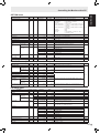
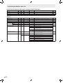
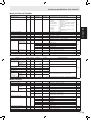
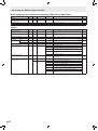
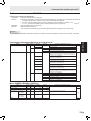
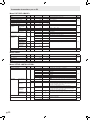
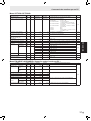
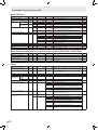
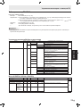
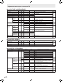
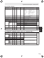
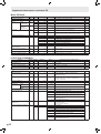
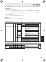
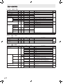
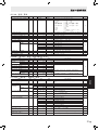
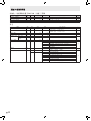
RS-232C command table ...........................................29
Troubleshooting and Specifications
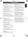
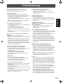
Troubleshooting .............................................................33
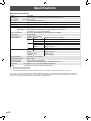
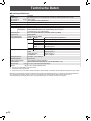
Specifications ................................................................
34

ENGLISH
7
E
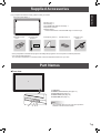
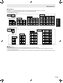
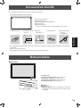
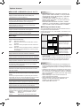
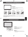
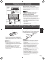
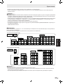
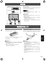
Supplied Accessories
If any component should be missing, please contact your dealer.
INPUT
� Liquid Crystal Display: 1
� Remote control
unit: 1
� Cable clamp: 2� Temporary stand: 2 � Power cord
clamp:
1
� Power cord: 1
� R-6 battery: 2
� CD-ROM (Utility Disk for Windows): 1
� Operation manual: 1
� Blank sticker: 1
Place a blank sticker onto the SHARP logo to cover the logo
.
� Vertical logo
sticker: 2
* Sharp Corporation holds authorship rights to the Utility Disk programme. Do not reproduce it without permission.
* For environmental protection!
Do not dispose of batteries in household waste. Follow the disposal instructions for your area.
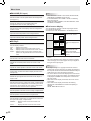
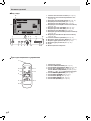
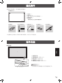
Part Names
Front view
IN
P
U
T
1
2 3
4
5
1. LCD panel
2. Remote control sensor (See page 13.)
3. Input switch (See page 15.)
4. Power switch (See page 14.)
5. Power LED (See page 14.)
TIPS
• Use a pointed object such as a pen tip to press the
switches at the front of the monitor.

8
E
8
E
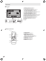
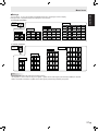
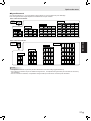
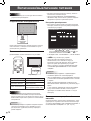
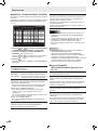
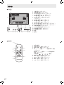
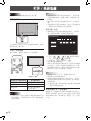
Part Names
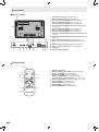
Rear view
1 6 8 9 11 14
2 3 4 5 7 10 12 1
3
15
16
1. Main power switch (See page 14.)
2. AC input terminal (See page 12.)
3. PC/AV output terminal (DVI-D) (See page 11.)
4. PC1 input terminal (DVI-D) (See page 10.)
AV1 input terminal
(DVI-D) (See page 10.)
5. PC2 input terminal (Mini D-sub 15 pin) (See page 10.)
6. PC3 input terminals (BNC) (See page 10.)
7. AV2 input terminals (BNC) (See page 10.)
8. AV3 input terminal (BNC) (See page 10.)
9. RS-232C output terminal (D-sub 9 pin) (See page 25.)
10. RS-232C input terminal (D-sub 9 pin) (See page 25.)
11. External speaker terminals (See page 11.)
12. PC/AV audio output terminals (See page 11.)
13. AV audio input terminals (See page 10.)
14. PC audio input terminal (See page 10.)
15. Handles
16. Vents
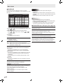
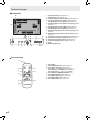
Remote control unit
1
2
3
4
5
6
9
8
7
1. Signal transmitter
2. POWER button (See page 14.)
3. MUTE button (See page 15.)
4. VOL +/- buttons (See page 15.)
BRIGHT +/- buttons (See page 15.)
Cursor control ( / / / ) buttons
5. DISPLAY button (See page 15.)
6. MODE button (See page 15.)
7. INPUT button (See page 15.)
8. MENU button (See page 17.)
9. SIZE button (See page 15.)

ENGLISH
9
E
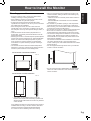
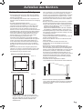
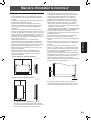
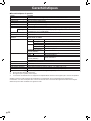
How to Install the Monitor
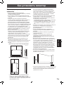
Mounting precautions
• Since the monitor is heavy, consult your dealer before
installing, removing or moving the monitor.
• When installing, removing or moving the monitor, ensure
that this is carried out by at least 2 people.
• A stand and mounting bracket compliant with VESA
specifications is required. Do not use any screw holes other
than VESA holes for installation.
• When moving the monitor, be sure to hold it with the
handles both on the rear and the unit bottom. Do not hold
the LCD panel. This may cause product damage, failure, or
injury.
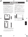
• Install the monitor with the surface perpendicular to a
level surface. If necessary, limit the tilt between 0 and 20
degrees downward.
• Mounting the monitor on the wall requires special expertise
and the work must be performed by an authorised SHARP
dealer. You should never attempt to perform any of this
work yourself. Our company will bear no responsibility
for accidents or injuries caused by improper mounting or
mishandling.
• This monitor should be used at an ambient temperature
between 0°C and 40°C. Provide enough space around the
monitor to prevent heat from accumulating inside.
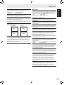
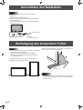
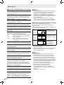
For the monitor in horizontal orientation
20
Unit: cm
5
5 5
For the monitor in vertical orientation
Unit: cm
*
*
5
5 5
20
* The monitor can be installed close to a wall, etc.
However, the monitor emits heat during operation. Be
aware that heat emitted from the monitor may discolour
or alter the wall.
If it is difficult to provide such space because the monitor is
installed inside a housing or for other reasons, take other
measures to keep the ambient temperature between
0°C and 40°C such as installing a fan in the housing.
• Adhere to the following when installing the monitor in the
vertical orientation. Failing to adhere to the following may
cause malfunctions.
- Install the monitor such that the power LED is located on
the downside.
- Set the MONITOR on the SETUP menu to PORTRAIT.
(See page 19.)
• Do not block any ventilation openings. If the temperature
inside the monitor rises, this could lead to a malfunction.
• After mounting, it is recommended to take some measures
to prevent the monitor from falling down.
• Do not place the monitor on a device which generates heat.
• Be sure to use a stand or a wall-mount/ceiling-mount
bracket designed or designated for mounting the monitor.
• This monitor is designed to be installed on a concrete wall/
ceiling or pillar. Reinforced work might be necessary for
some materials such as plaster / thin plastic board / wood
before starting installation.
This monitor and bracket must be installed on a wall which
can endure at least 4 times or more the weight of the
monitor. Install by the most suitable method for the material
and the structure.
• Use the supplied vertical logo sticker when you install the
monitor in vertical orientation.
*
INPUT
* Do not remove the factory-affixed sticker but affix the logo
sticker over it. Be careful not to cover the remote control
sensor or buttons.

10
E
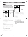
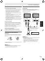
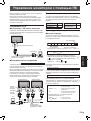
Connecting Peripheral Equipment
Caution
• Be sure to turn off the main power switch and disconnect
the plug from the power outlet before connecting/
disconnecting cables. Also, read the manual of the
equipment to be connected.
• Be careful not to mix up the input terminal with the output
terminal when connecting cables. Mixing up the input and
output terminals may cause malfunctions and the other
problems.
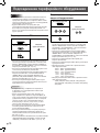
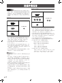
Connection with a PC
PC1 input terminal
PC audio input terminal
PC2 input terminal
PC3 input terminals
HV
R G
B
• Use a commercially available signal cable (DVI-D 24
pin) for the PC1 input terminal. Set DVI SELECT on the
OPTION menu to PC (DIGITAL) when using the PC1 input
terminal. (See page 19.)
• Use a commercially available signal cable (Mini D-sub
15 pin) for the PC2 input terminal.
• Use a commercially available signal cable (BNC) for the
PC3 input terminals. Set BNC SELECT on the OPTION
menu to PC (ANALOG) when using the PC3 input
terminals. (See page 19.)
• Use a commercially available audio cable (mini stereo jack)
for the PC audio input terminal. Use an audio cable without
resistance.
TIPS
• Images may not be displayed properly depending on the
computer (graphics board) to be connected.
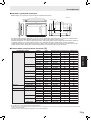
• A screen with 1920 x 1080 resolution may not be displayed
correctly on PC3 (BNC). In this case, check the settings of
your computer (graphics board) to verify that input signals
conform to specifications of this monitor (Hsync: 66.3 kHz,
Vsync: 60 Hz, and Dot frequency: 148.5 MHz). (See page
35.)
• If there is a check box to disable EDID in display control
panel, check it when using PC3 (BNC).
• Use the automatic screen adjustment when a PC screen is
displayed for the first time using PC2 or PC3, or when the
setting of the PC is changed. (See page 23.)
• The screen is adjusted automatically when SELF ADJUST
in the OPTION menu is set to “ON”. (See page 19.)
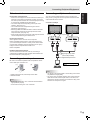
Connection with AV equipment
AV1 input terminal
AV audio input terminals
AV2 input terminals
AV3 input terminal
Cr/Pr Y Cb/Pb
• Use a commercially available signal cable (DVI-D 24 pin)
for the AV1 input terminal. Set DVI SELECT on the OPTION
menu to AV (DIGITAL) when using the AV1 input terminal.
(See page 19.)
• Use a commercially available component cable (BNC) for
the AV2 input terminals. Set BNC SELECT on the OPTION
menu to AV (COMPONENT) when using the AV2 input
terminals. (See page 19.)
• Use a commercially available video cable (BNC) for the
AV3 input terminal.
• Use a commercially available audio cable (RCA) for the AV
audio input terminals.
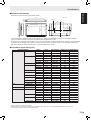
• The AV1 input terminal is compatible with the video signals
below:
1920 x 1080 p @ 50/59.94/60 Hz
1920 x 1080 i @ 50/59.94/60 Hz
1280 x 720 p @ 50/59.94/60 Hz
720 x 576 p @ 50 Hz
720 x 480 p @ 59.94/60 Hz
640 x 480 p @ 59.94/60 Hz
• The AV2 input terminals are compatible with the video
signals below:
1080i (1125i)/50, 1080i (1125i)/60, 720p (750p)/50,
720p (750p)/60, 576p (625p), 576i (625i), 480p (525p),
480i (525i)

ENGLISH
E
11
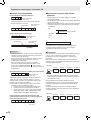
Connecting Peripheral Equipment
Other terminals
PC/AV audio output terminals
• Audio from the equipment connected to the AV audio input
terminals or PC audio input terminal is output. Connect to
the audio input terminals of the connected equipment using
a commercially available audio cable (RCA).
• The audio output varies depending on the input mode
selection. (See page 15.)
• The volume level can be adjusted using the volume
adjustment. (See page 15.)
• Selecting FIXED of “AUDIO OUTPUT” from the OPTION
menu fixes the volume of sound output from the audio
output terminals. (See page 19.)
• Audio signals output from the PC/AV audio output terminals
cannot be adjusted using the AUDIO menu.
PC/AV output terminals
Video signals from PC1 and AV1 can be output to
HDCP-compatible external device. Use this terminal when
you connect multiple monitors in a daisy chain via DVI cable
(commercially available). (See the description on the right.)
Images cannot be output to device that is not
HDCP-compatible.
RS-232C input/output terminals
You can control the monitor from a PC by connecting a
commercially available RS-232C straight cable between this
terminal and the PC. (See page 25.)
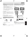
Connecting external speakers
Be sure to use external speakers with an impedance of 6 Ω
and a rated input of at least 7 W.
(1) (2)
1. While pushing the tab, insert the tip of the cable.
2. Release the tab.
TIPS
• Be sure to connect the + and - terminals and the left and
right speakers properly.
• Avoid short circuiting the + and - terminals.
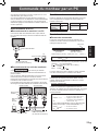
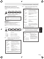
Connecting multiple monitors
You can connect multiple monitors (up to 5 monitors) in a
daisy chain by using the PC1/AV1 input terminals and PC/AV
output terminals of this monitor.
Connection example
shows the signal flow
PC/AV output
terminal
PC1/AV1 input terminals
Digital signal (DVI) cables
(commercially available)
To PC digital RGB output terminal
First monitor Second monitor
TIPS
• The length of the signal cables or surrounding environment
may affect the image quality.
• The screen may not display properly when using terminals
other than PC1/AV1 for the input mode. In this case, turn
off the power to all the monitors connected in a daisy chain
and then turn the power on again.

12
E
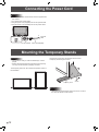
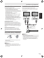
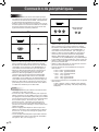
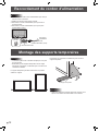
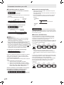
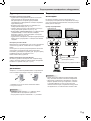
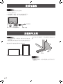
Connecting the Power Cord
Caution
• Do not use a power cord other than the one supplied with
the monitor.
1. Turn off the main power switch.
2. Plug the power cord (supplied) into the AC input terminal.
3. Plug the power cord (supplied) into the AC power outlet.
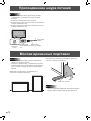
Caution
• The monitor is heavy. It must be handled by 2 or more
people.
• Please note that the temporary stands are for temporary
use only until the monitor is properly mounted.
The temporary stand can be mounted at a position shown in
the illustration.
Remove the screws from the monitor and mount the
temporary stand using the screws.
Temporary stand
Screws
Caution
• After detaching the temporary stand, be sure to re-mount
the removed screws on the monitor.
Mounting the Temporary Stands
For power
outlet
Power cord (Supplied)
AC input terminal
2
3
1
Main power switch

ENGLISH
13
E
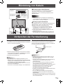
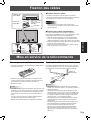
Installing the batteries
1. Press the cover gently and slide it in the direction of the
arrow.
2. See the instructions in the compartment and put in the
supplied batteries (2 R-6 batteries) with their plus (+) and
minus (-) sides oriented correctly.
3. Close the cover.
TIPS
• The supplied batteries (2 R-6 batteries) may become
exhausted faster depending on the storage condition. It is
recommended that you replace them with new batteries
(commercially available) earlier than specified.
• If you will not use the remote control for a long time,
remove the batteries.
• Use manganese or alkaline batteries only.
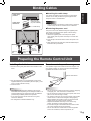
Remote control operation range
The operation range of the remote control unit is approx. 5 m
at an angle of approx 10° from the centre to the top/bottom/
right/left of the remote control sensor.
10°
5
m
5 m
5 m
Remote control sensor
10°
TIPS
• Do not expose the remote control unit to shock by dropping
or stepping on it. This could lead to a malfunction.
• Do not expose the remote control unit to liquids, and do not
place it in an area with high humidity.
• The remote control unit may not work properly if the remote
control sensor is under direct sunlight or strong lighting.
• Objects between the remote control unit and the remote
control sensor may prevent proper operation.
• Replace the batteries when they run low as this may
shorten the remote control’s operation range.
• If a fluorescent light is illuminated near the remote control
unit, it may interfere with proper operation.
• Do not use it with the remote control of other equipment
such as air conditioner, stereo components, etc.
Preparing the Remote Control Unit
Binding Cables
1 2 3
Hole for
the power
cord clamp
Fastened
part
Band
Power cord
clamp
Cable clamp
Insert the cable
clamp into a hole.
(any hole available)
Cable clamp
attachment
Cable clamp
positions
Attaching the cable clamp
The cables connected to the terminals on the back of the
monitor can be neatly bundled using the supplied cable
clamps as shown in the illustration.
Caution
• Verify the position for attaching a cable clamp in advance.
A cable clamp cannot be removed once it is attached.
Fastening the power cord
The power cord can be fastened using the supplied power
cord clamp. This will prevent the power cord from being
disconnected accidentally.
1. Attach the supplied power cord clamp to the power
cord, making sure the power cord clamp is circular hole-
sidedown.
2. Insert the tip of the band into the hole for the power cord
clamp.
3. While holding the tail of the band, slide the fastened part
toward the AC input terminal.

14
E
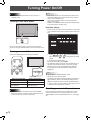
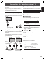
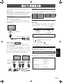
Turning Power On/Off
Caution
• Turn on the monitor first before turning on the PC or
playback device.
Turning on the main power
Main power switch
When the main power switch is off, the monitor cannot be
turned on using the POWER button on the remote control unit.
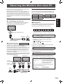
Turning power on/off
Press the POWER button to turn the power ON/OFF.
INPUT
Power LED
Status of a power LED Status of the monitor
Green lighting Power “On”
Orange lighting Power “Off” (Standby mode)
Green flashing
Input signal standby mode
(input using a PC)
Caution
• When switching the main power switch or the POWER
button off and back on, always wait for at least 5 seconds.
A short interval may result in a malfunction.
TIPS
• If the monitor is in the input signal standby mode and you
press the POWER button on the remote control unit, the
monitor enters standby mode.
• You can turn on/off the monitor by pressing the power
switch of the monitor.
• Setting the SCHEDULE flashes the power LED alternately
in red and orange in standby mode.
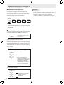
Date/time setting
• If the time has yet to be set when the monitor is first turned
on, the date/time setting screen appears. Set the date and
time.
DATE/TIME SETTING
SET
CANCEL
07
/ /
OK
…
[MENU]
20
01
/
01
/
00 00
:
: :
1. Press , ,
or to select the date and
time, and press or to change the numerical
values.
2. Select SET and then press
MENU
.
• Be sure to set the date and time.
• The date/time setting screen will close automatically if no
operation is performed for about 15 seconds. The date
and time can be set using DATE/TIME SETTING from
the OPTION menu when the date/time setting screen
disappears.
TIPS
•
Set the date in “Year/Month/Day” order.
•
Set the time on a 24-hour basis.
•
The clock stops after the power-off status continues for
approximately 1 week.* The date/time setting screen
appears at power-on. Be sure to set the date and time.
(
* This is a guide. The power-off status that stops the clock
depends on the status of the monitor.)
Disabling power on/off operations
Power on/power off operations can be disabled in order to
protect the monitor from an accidental power off. Set the
ADJUSTMENT LOCK in FUNCTION menu to “2”. (See page
24.)

ENGLISH
15
E
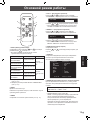
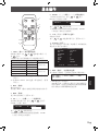
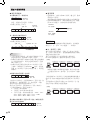
Basic Operation
1
2
3
4
5
6
7
8
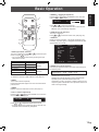
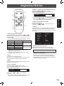
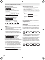
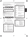
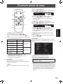
1. INPUT (Input mode selection)
The menu is displayed. Press or to select the input
mode, and press to enter.
* You can select the input terminal by pressing the input
switch of the monitor.
Input mode Video Audio
PC1 DIGITAL
*1
PC1 input terminal
PC audio input
terminal
PC2 ANALOG
PC2 input terminal
PC3 ANALOG
*2
PC3 input terminals
AV1 DIGITAL
*1
AV1 input terminal
AV audio input
terminals
AV2 COMPONENT
*2
AV2 input terminals
AV3 VIDEO AV3 input terminal
*1 Select the terminal for DVI SELECT. (See page 19.)
*2 Select the terminal for BNC SELECT. (See page 19.)
2. MUTE
Turns off the volume temporarily.
Press the MUTE button again to turn the sound back to the
previous level.
3. MENU
Displays and turns off the menu screen (see page 17).
4. VOL +/- (Volume adjustment)
Pressing or displays the VOLUME menu when the
menu screen is not displayed.
V O L U M E 15
Press or to adjust the volume of the sound.
* If you do not press any buttons for about 4 seconds, the
VOLUME menu automatically disappears.
5. BRIGHT +/- (Backlight adjustment)
Pressing or displays the BRIGHT menu when the
menu screen is not displayed.
B R I G H T 15
Press or to adjust the brightness.
* If you do not press any buttons for about 4 seconds, the
BRIGHT menu automatically disappears.
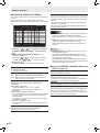
6. SIZE (Screen size selection)
The menu is displayed.
Press or to select the screen size. (See page 16.)
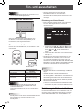
7. DISPLAY
Displays monitor information. The display disappears when
this button is pressed again or disappears automatically after
approximately 15 seconds.
INPUT MODE
SIZE
COLOR MOD
E
BRIGHT
VOLUM
E
ID No.
MODE
L
S/N
PC2 ANALOG
WIDE
ST
D
15
15
0
PN-465
E
XXXXXXXX
:
:
:
:
:
:
:
:
1 0 2 4 x 7 6 8
INFORMATION XXXX/XX/XX XXX XX:XX:X
X
V: 60 Hz H: 48.4 kH
z
8. MODE (Colour mode selection)
Each time you press this button, the colour mode changes in
the following order:
STD (Standard) → VIVID → sRGB → STD...
• sRGB applies to PC input only.
sRGB is international standard of colour representation
specified by IEC (International Electrotechnical
Commission). Colour conversion is made in taking account
of liquid crystal’s characteristics and represents colour tone
close to its original image.

E
16
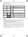
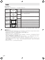
Basic Operation
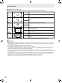
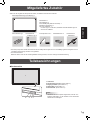
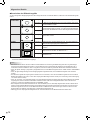
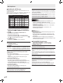
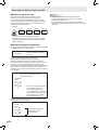
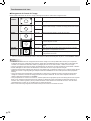
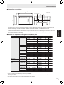
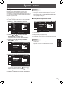
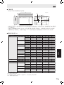
Switching the screen size
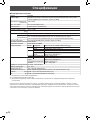
Even when the screen size is changed, the display may remain the same depending on the input signal.
WIDE PC input Displays image so it fills the entire screen.
AV input An image with a 4:3 aspect ratio is stretched to fill the entire screen.
ZOOM 1 PC input An image with a 4:3 aspect ratio is enlarged to fill the entire screen
without changing the aspect ratio. The edges of the image may be
cut off.
AV input
ZOOM 2 PC input Use this size if ZOOM 1 cuts off the subtitles.
AV input
NORMAL PC input Displays image so it fills the screen without changing the aspect
ratio of the input signals.
AV input
Displays the entire image of the aspect ratio of 4:3 without changing
the aspect ratio.
DotbyDot PC input Displays the dots of the signals input from the connected PC as the
corresponding dots on the screen. *
AV input
Displays the dots of the input signals as the corresponding dots on
the screen.
*: With a monitor with a screen resolution of 1600 x 1200, selecting DotbyDot displays the NORMAL screen.
TIPS
• Using this monitor’s screen-size switching or dual-screen display functions to compress or expand the screen for commercial
or public viewing in establishments like cafes or hotels may infringe on the rights of the creators, as protected by Copyright
Law, so please be careful.
• When “Enlarge” is set, the screen size is fixed to “WIDE” mode.
• When dual-screen display is selected, the screen size cannot be changed.
• The appearance of the original video may change if you select a screen size with a different aspect ratio than the original
image (e.g. TV broadcast or video input from external equipment).
• When an ordinary non-wide image (4:3) is viewed with the whole screen using the screen-size switching function of this
monitor, the edge of the image may be lost or appear distorted. If you wish to respect the creator’s intentions, set the screen
size to “NORMAL”.
• When playing commercial software, parts of the image (like subtitles) may be cropped. In this case select the optimal screen
size using the screen-size switching function of this monitor. With some software, there may be noise or distortion at the
edges of the screen. This is due to the characteristics of the software, and is not a malfunction.
• Depending on the original image size, black bands may remain at the edges of the screen.

ENGLISH
17
E
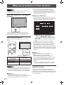
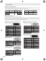
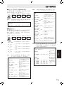
Menu Items
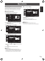
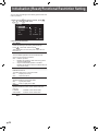
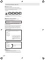
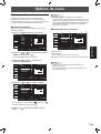
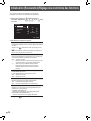
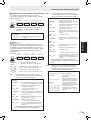
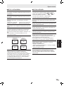
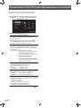
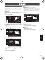
Displaying the menu screen
Video and audio adjustment and settings of various functions
are enabled. This section describes how to use the menu
items. See pages 18 to 20 for details of each menu items.
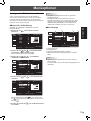
Example of operation
(Adjusting CONTRAST in the PICTURE menu)
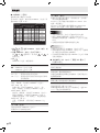
1. Press
MENU
to display the menu screen.
1 0 2 4 x 7 6 8
V: 60 Hz H: 48.4 kHz
AUTO
CLOC
K
PHASE
H-POS
V-POS
RESE
T
SCREEN
PICTURE
AUDIO
SETUP
OPTION
ENLARGE
PIP/PbyP
127
31
150
31
SCREEN PC2 ANALOG1/1
END
…
[MENU]
2. Press
or
to select PICTURE, and press .
PICTURE menu is displayed.
3. Press
or
to select CONTRAST.
AUTO
CONTRAST
BLACK LEVEL
SHARPNESS
30
96
12
PC2 ANALOG1/2
PICTURE
SCREEN
PICTURE
AUDIO
SETUP
OPTION
ENLARGE
PIP/PbyP
OK
…
[MENU]
1 0 2 4 x 7 6 8
V: 60 Hz H: 48.4 kHz
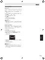
4. Press or
to adjust the setting.
AUTO
CONTRAST
BLACK LEVEL
SHARPNESS
40
96
12
PC2 ANALOG1/2
PICTURE
SCREEN
PICTURE
AUDIO
SETUP
OPTION
ENLARGE
PIP/PbyP
OK
…
[MENU]
1 0 2 4 x 7 6 8
V: 60 Hz H: 48.4 kHz
For items that have , press , make settings and then
press
MENU
.
5. Press
MENU
twice to close the menu screen.
TIPS
• The menu will differ depending on the input mode.
• The menu screen will close automatically if no operation is
performed for about 15 seconds. (DATE/TIME SETTING
and SCHEDULE screens will close in about 4 minutes.)
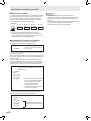
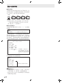
Menu screen display
AUTO
CONTRAST
BLACK LEVEL
SHARPNESS
30
96
12
PC2 ANALOG1/2
PICTURE
SCREEN
PICTURE
AUDIO
SETUP
OPTION
ENLARGE
PIP/PbyP
OK
…
[MENU]
1 0 2 4 x 7 6 8
V: 60 Hz H: 48.4 kHz
4
1 3 2
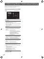
1 Name of the menu
2 Input mode
3 An item being selected (highlighted)
4 Screen resolution of input signal, and other data.
TIPS
• Items that cannot be selected appear in grey.
(e.g. Function not supported by the current input signal)

E
18
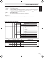
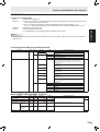
Menu item details
The menu will differ depending on the input mode.
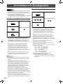
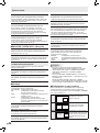
SCREEN (PC2/PC3)
AUTO
The CLOCK, PHASE, H-POS, and V-POS are automatically
adjusted.
Pressing
performs adjustment.
Use this automatic adjustment when you use the PC2 input
terminal or PC3 input terminals to display a PC screen for
the first time or when you change the setting of the PC. (See
page 23.)
CLOCK
Adjusts frequency for sampling clock for applicable video.
Adjust when there is flickering in the form of vertical stripes.
When using the adjustment pattern (see page 23), make
adjustments so that no vertical stripe noise appears in it.
PHASE
Adjusts sampling clock phase for applicable video.
Useful when small characters appear with low contrast and/
or there are flickers at corners.
When using the adjustment pattern (see page 23), make
adjustments so that no horizontal stripe noise appears in it.
* Adjustments to PHASE should be made only after CLOCK
has been correctly set.
H-POS
Adjust the horizontal position of the image.
V-POS
Adjust the vertical position of the image.
RESET
Resets the values of the SCREEN menu items to the factory
preset values.
Select “ON” and then press
MENU
.
PICTURE
AUTO (PC2/PC3)
The CONTRAST and BLACK LEVEL are automatically
adjusted.
Pressing
performs adjustment.
CONTRAST
Adjusts the brightness of the image.
BLACK LEVEL
Adjusts the entire brightness of the video signals.
TINT (AV input)
Adjusts the hue. Selecting + changes the colour towards
green, and selecting - changes it towards magenta.
COLORS (AV input)
Adjusts the colour intensity.
SHARPNESS
Adjusts the sharpness of the image.
ADVANCED (AV input)
You can adjust more specifically. (See page 22.)
COLOR MODE
Changes the colour mode on the screen. The colour mode
on the screen can also be changed using a remote control
unit. (See page 15.)
* sRGB is PC input only. See page 15 for details.
WHITE BALANCE
THRU .............. Displays the input signal level as is.
(for PC1 only)
PRESET ......... Selects the colour temperature using
PRESET.
USER .............. Used for adjusting R-CONTRAST,
G-CONTRAST, and B-CONTRAST
respectively.
PRESET
Selects the colour temperature when the WHITE BALANCE
is set to PRESET.
R-CONTRAST
Adjusts red component when the WHITE BALANCE is set to
USER.
G-CONTRAST
Adjusts green component when the WHITE BALANCE is set
to USER.
B-CONTRAST
Adjusts blue component when the WHITE BALANCE is set
to USER.
COPY TO USER
Copies the value set for PRESET to the USER setting.
Select “ON” and then press
MENU
.
GAMMA
Select a gamma value.
RESET
Resets the values of the PICTURE menu items to the factory
preset values.
Select “ON” and then press
MENU
.
AUDIO
TREBLE
Adjusts the volume of treble-level sound.
BASS
Adjusts the volume of bass-level sound.
BALANCE
Adjusts the balance of the audio sound between right and left.
RESET
Resets the values of the AUDIO menu items to the factory preset values.
Select “ON” and then press
MENU
.
SETUP
OSD H-POSITION
Adjusts the horizontal display position of menu screen.
OSD V-POSITION
Adjusts the vertical display position of menu screen.
Menu Items
La page est en cours de chargement...
La page est en cours de chargement...
La page est en cours de chargement...
La page est en cours de chargement...
La page est en cours de chargement...
La page est en cours de chargement...
La page est en cours de chargement...
La page est en cours de chargement...
La page est en cours de chargement...
La page est en cours de chargement...
La page est en cours de chargement...
La page est en cours de chargement...
La page est en cours de chargement...
La page est en cours de chargement...
La page est en cours de chargement...
La page est en cours de chargement...
La page est en cours de chargement...
La page est en cours de chargement...
La page est en cours de chargement...
La page est en cours de chargement...
La page est en cours de chargement...
La page est en cours de chargement...
La page est en cours de chargement...
La page est en cours de chargement...
La page est en cours de chargement...
La page est en cours de chargement...
La page est en cours de chargement...
La page est en cours de chargement...
La page est en cours de chargement...
La page est en cours de chargement...
La page est en cours de chargement...
La page est en cours de chargement...
La page est en cours de chargement...
La page est en cours de chargement...
La page est en cours de chargement...
La page est en cours de chargement...
La page est en cours de chargement...
La page est en cours de chargement...
La page est en cours de chargement...
La page est en cours de chargement...
La page est en cours de chargement...
La page est en cours de chargement...
La page est en cours de chargement...
La page est en cours de chargement...
La page est en cours de chargement...
La page est en cours de chargement...
La page est en cours de chargement...
La page est en cours de chargement...
La page est en cours de chargement...
La page est en cours de chargement...
La page est en cours de chargement...
La page est en cours de chargement...
La page est en cours de chargement...
La page est en cours de chargement...
La page est en cours de chargement...
La page est en cours de chargement...
La page est en cours de chargement...
La page est en cours de chargement...
La page est en cours de chargement...
La page est en cours de chargement...
La page est en cours de chargement...
La page est en cours de chargement...
La page est en cours de chargement...
La page est en cours de chargement...
La page est en cours de chargement...
La page est en cours de chargement...
La page est en cours de chargement...
La page est en cours de chargement...
La page est en cours de chargement...
La page est en cours de chargement...
La page est en cours de chargement...
La page est en cours de chargement...
La page est en cours de chargement...
La page est en cours de chargement...
La page est en cours de chargement...
La page est en cours de chargement...
La page est en cours de chargement...
La page est en cours de chargement...
La page est en cours de chargement...
La page est en cours de chargement...
La page est en cours de chargement...
La page est en cours de chargement...
La page est en cours de chargement...
La page est en cours de chargement...
La page est en cours de chargement...
La page est en cours de chargement...
La page est en cours de chargement...
La page est en cours de chargement...
La page est en cours de chargement...
La page est en cours de chargement...
La page est en cours de chargement...
La page est en cours de chargement...
La page est en cours de chargement...
La page est en cours de chargement...
La page est en cours de chargement...
La page est en cours de chargement...
La page est en cours de chargement...
La page est en cours de chargement...
La page est en cours de chargement...
La page est en cours de chargement...
La page est en cours de chargement...
La page est en cours de chargement...
La page est en cours de chargement...
La page est en cours de chargement...
La page est en cours de chargement...
La page est en cours de chargement...
La page est en cours de chargement...
La page est en cours de chargement...
La page est en cours de chargement...
La page est en cours de chargement...
La page est en cours de chargement...
La page est en cours de chargement...
La page est en cours de chargement...
La page est en cours de chargement...
La page est en cours de chargement...
La page est en cours de chargement...
La page est en cours de chargement...
La page est en cours de chargement...
La page est en cours de chargement...
La page est en cours de chargement...
La page est en cours de chargement...
La page est en cours de chargement...
La page est en cours de chargement...
La page est en cours de chargement...
La page est en cours de chargement...
La page est en cours de chargement...
La page est en cours de chargement...
La page est en cours de chargement...
La page est en cours de chargement...
La page est en cours de chargement...
La page est en cours de chargement...
La page est en cours de chargement...
La page est en cours de chargement...
La page est en cours de chargement...
La page est en cours de chargement...
La page est en cours de chargement...
La page est en cours de chargement...
La page est en cours de chargement...
La page est en cours de chargement...
La page est en cours de chargement...
La page est en cours de chargement...
La page est en cours de chargement...
La page est en cours de chargement...
La page est en cours de chargement...
La page est en cours de chargement...
La page est en cours de chargement...
La page est en cours de chargement...
La page est en cours de chargement...
La page est en cours de chargement...
La page est en cours de chargement...
La page est en cours de chargement...
La page est en cours de chargement...
La page est en cours de chargement...
La page est en cours de chargement...
La page est en cours de chargement...
La page est en cours de chargement...
La page est en cours de chargement...
La page est en cours de chargement...
La page est en cours de chargement...
La page est en cours de chargement...
La page est en cours de chargement...
La page est en cours de chargement...
La page est en cours de chargement...
La page est en cours de chargement...
-
 1
1
-
 2
2
-
 3
3
-
 4
4
-
 5
5
-
 6
6
-
 7
7
-
 8
8
-
 9
9
-
 10
10
-
 11
11
-
 12
12
-
 13
13
-
 14
14
-
 15
15
-
 16
16
-
 17
17
-
 18
18
-
 19
19
-
 20
20
-
 21
21
-
 22
22
-
 23
23
-
 24
24
-
 25
25
-
 26
26
-
 27
27
-
 28
28
-
 29
29
-
 30
30
-
 31
31
-
 32
32
-
 33
33
-
 34
34
-
 35
35
-
 36
36
-
 37
37
-
 38
38
-
 39
39
-
 40
40
-
 41
41
-
 42
42
-
 43
43
-
 44
44
-
 45
45
-
 46
46
-
 47
47
-
 48
48
-
 49
49
-
 50
50
-
 51
51
-
 52
52
-
 53
53
-
 54
54
-
 55
55
-
 56
56
-
 57
57
-
 58
58
-
 59
59
-
 60
60
-
 61
61
-
 62
62
-
 63
63
-
 64
64
-
 65
65
-
 66
66
-
 67
67
-
 68
68
-
 69
69
-
 70
70
-
 71
71
-
 72
72
-
 73
73
-
 74
74
-
 75
75
-
 76
76
-
 77
77
-
 78
78
-
 79
79
-
 80
80
-
 81
81
-
 82
82
-
 83
83
-
 84
84
-
 85
85
-
 86
86
-
 87
87
-
 88
88
-
 89
89
-
 90
90
-
 91
91
-
 92
92
-
 93
93
-
 94
94
-
 95
95
-
 96
96
-
 97
97
-
 98
98
-
 99
99
-
 100
100
-
 101
101
-
 102
102
-
 103
103
-
 104
104
-
 105
105
-
 106
106
-
 107
107
-
 108
108
-
 109
109
-
 110
110
-
 111
111
-
 112
112
-
 113
113
-
 114
114
-
 115
115
-
 116
116
-
 117
117
-
 118
118
-
 119
119
-
 120
120
-
 121
121
-
 122
122
-
 123
123
-
 124
124
-
 125
125
-
 126
126
-
 127
127
-
 128
128
-
 129
129
-
 130
130
-
 131
131
-
 132
132
-
 133
133
-
 134
134
-
 135
135
-
 136
136
-
 137
137
-
 138
138
-
 139
139
-
 140
140
-
 141
141
-
 142
142
-
 143
143
-
 144
144
-
 145
145
-
 146
146
-
 147
147
-
 148
148
-
 149
149
-
 150
150
-
 151
151
-
 152
152
-
 153
153
-
 154
154
-
 155
155
-
 156
156
-
 157
157
-
 158
158
-
 159
159
-
 160
160
-
 161
161
-
 162
162
-
 163
163
-
 164
164
-
 165
165
-
 166
166
-
 167
167
-
 168
168
-
 169
169
-
 170
170
-
 171
171
-
 172
172
-
 173
173
-
 174
174
-
 175
175
-
 176
176
-
 177
177
-
 178
178
-
 179
179
-
 180
180
-
 181
181
-
 182
182
-
 183
183
-
 184
184


Sharp PN-465E Mode d'emploi
- Catégorie
- Téléviseurs
- Taper
- Mode d'emploi
- Ce manuel convient également à
dans d''autres langues
- English: Sharp PN-465E Operating instructions
- Deutsch: Sharp PN-465E Bedienungsanleitung
- русский: Sharp PN-465E Инструкция по эксплуатации
Documents connexes
-
Sharp PNG655RE Mode d'emploi
-
-
-
-
-
-
-
-
Sharp PN-E471 Manuel utilisateur