
NOTE: THIS INSTRUCTION
BOOKLET CONTAINS IMPORTANT
SAFETY INFORMATION.
PLEASE READ AND KEEP FOR
FUTURE REFERENCE.
Enlish p 1-14
Français p 15-17
Español p 18-20
Lot # 371387 03/31/15
Purchased: __________________
Be sure to ive us a rin before
makin any returns. 1-800-523-3987
4-Drawer Chest
Soft Modern Collection | 419198
Need help? Visit Sauder.com to view video assembly tips or chat with a live rep.
Prefer the phone? Call 1-800-523-3987.
Share your journey!
sauder.com
The dresser's
not-so-distant cousin.

Table of Contents Assembly Tools Required
Hammer
Not actual size
No. 2 Phillips Screwdriver
Tip Shown Actual Size
Part Identifi cation
Hardware Identifi cation
Assembly Steps
Français
Español
Safety
Warranty
3
4
5-14
15-17
18-20
21-22
23
419198 www.sauder.com/servicesPae 2

å While not all parts are labeled, some of the parts will have a label or an inked letter on the ede
to help distinuish similar parts from each other. Use this part identifi cation to help identify similar parts.
Part Identifi cation
A
B
C
D
E
F
D
H
D985
D30
D80
D31
G
419198www.sauder.com/services
Pae 3
M67
A RIGHT END (1)
B LEFT END (1)
C TOP (1)
D BOTTOM (2)
E BACK (1)
F SKIRT (1)
G DRAWER FRONT (4)
H HANDLE (4)
D30 RIGHT DRAWER SIDE (4)
D31 LEFT DRAWER SIDE (4)
D80 DRAWER BACK (4)
D985 DRAWER BOTTOM (4)
M67 DRAWER BRACE (4)

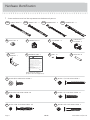
å Screws are shown actual size. You may receive extra hardware with your unit.
Hardware Identifi cation
30S
BLACK 1-9/16" FLAT HEAD SCREW - 20
10A
SLIDE CAM - 8
BLACK 9/16" LARGE HEAD SCREW - 1
1S
3S
GOLD 5/16" FLAT HEAD SCREW - 36
1F
HIDDEN CAM - 8
2F
CAM DOWEL - 8
10F
TWIST-LOCK
®
FASTENER - 4
SILVER 1-1/8" FLAT HEAD SCREW - 12
10S
METAL PIN - 6
1R
1N
NAIL - 41
SAFETY
BRACKET - 1
1G
BLACK 1-7/8" FLAT HEAD SCREW - 1
2S
BROWN 1-5/8" FLAT HEAD SCREW - 3
55S
35GA
CABINET RIGHT -4
35GB
CABINET LEFT - 4
35GC
DRAWER RIGHT - 4
35GD
DRAWER LEFT - 4
(Refer to the last step for
proper location and application)
WARNING
Serious or fatal crushing injuries can occur
from furniture tip-over. To help prevent tip-
over:
• Place heaviest items in the lowest drawers.
• Unless specifi cally desined to accommodate, do
not
set TVs or other heavy objects on top of this product.
• Never allow children to climb or han on drawers,
doors, or shelves.
• Never open more than one drawer at a time.
• If equipped with a drawer interlock system, do not
defeat or remove it.
Use of tip-over restraints may only reduce, but not
eliminate, the risk of tip-over.
This is a permanent label. Do not attempt to remove!
04/10 332296
5L
WARNING LABEL - 1
419198 www.sauder.com/servicesPae 4

Step 1
å
Assemble your unit on a carpeted floor or on the empty
carton to avoid scratching your unit or the floor.
å
To begin assembly, push a SAUDER TWIST-LOCK®
FASTENER (10F) into the large holes in the ENDS (A and B).
10F
B
A
Do not tihten the TWIST-LOCK® FASTENERS in this step
Look for this icon. It means a
video assembly tip is available at
www.sauder.com/services/tips
419198www.sauder.com/services
Pae 5

Step 2
å
Push eiht HIDDEN CAMS (1F) into the BOTTOMS (D) and
DRAWER BRACES (I). Then, insert the metal end of a CAM
DOWEL (2F) into each HIDDEN CAM.
Insert the metal end of the CAM
DOWEL into the HIDDEN CAM.
Arrow
Do not tihten the HIDDEN CAMS in this step.
(8 used)
Arrow
1F
2F
Arrow
1F
2F
D
D
I
I
I
I
419198 www.sauder.com/servicesPae 6

å
Fasten four CABINET RIGHTS (35GA) to the RIGHT END (A)
and four CABINET LEFTS (35GB) to the LEFT END (B). Use
sixteen GOLD 5/16" FLAT HEAD SCREWS (3S) throuh holes
#1 and #3.
Step 3
GOLD 5/16" FLAT HEAD SCREW
(16 used in this step)
3S
Roller end
Finished ede
Roller end
Finished ede
1
2
3
1
2
3
1
2
3
1
2
3
1
2
3
1
2
3
1
2
3
A
B
419198www.sauder.com/services
Pae 7
Remember:
Rihty tihty.
Lefty loosey.

å
Fasten one of the BOTTOMS (D) to the SKIRT (F). Use
three BROWN 1-5/8" FLAT HEAD SCREWS (55S).
å
Insert six METAL PINS (1R) into the BOTTOMS (D) and
SKIRT (F).
å
Fasten the BOTTOMS (D) to the ENDS (A and B). Tihten
four HIDDEN CAMS.
å
NOTE: Be sure the METAL PINS (1R) in the BOTTOMS (D)
and SKIRT (F) insert into the ENDS (A and B).
Step 4
1R
1R
Unfi nished ede
Surface without TWIST-LOCK
®
FASTENERS
Surface with
TWIST-LOCK®
FASTENERS
Surface with HIDDEN CAMS
Surface with HIDDEN CAMS
Unfi nished
ede
F
A
B
Finished surface
These edes
should be even.
D
D
D
F
Finished ede
Surface without HIDDEN CAMS
BLACK 1-5/8" FLAT HEAD SCREW
(3 used in this step)
55S
Do not stand the unit upriht without the
BACK fastened. The unit may collapse.
Caution
Start Tihten
Arrow
Minimum
190 derees
Caution
Risk of damae or
injury. HIDDEN CAMS
must be completely
tihtened. HIDDEN
CAMS that are not
completely tihtened
may loosen, and parts
may separate. To
completely tihten:
Arrow
Maximum
210 derees
Unfi nished ede
419198 www.sauder.com/servicesPae 8

å
Fasten the TOP (C) to the ENDS (A and B). Tihten four
TWIST-LOCK® FASTENERS.
Step 5
Surface with holes
C
A
B
How to use the SAUDER TWIST-LOCK
®
FASTENER
1. Insert the dowel end of the FASTENER into the hole of the
adjoinin part.
NOTE: The dowel end of the FASTENER must remain fully
inserted in the hole of the adjoinin part while lockin the
FASTENER.
2. Tihten the FASTENER with a Phillips screwdriver as tiht
as possible.
Unfi nished ede
419198www.sauder.com/services
Pae 9
Don't worry. It isn't
Rome. This can be built
in a day.

å
Unfold the BACK (E) and lay it over your unit.
å
Make equal marins alon all four edes of the BACK (E). Push
on opposite corners of your unit if needed to make it “square”.
å
Fasten the BACK (E) to your unit usin the NAILS (1N).
Step 6
E
NAIL
(40 used in this step)
1N
Do not stand the unit upriht without the
BACK fastened. The unit may collapse.
Caution
419198 www.sauder.com/servicesPae 10
Printed information
must be facin up.

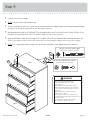
Step 7
å
Insert the DRAWER SIDES (D30 and D31 ) at an angle
into the slot at each end of the DRAWER FRONT (G).
å
Slide the DRAWER BOTTOM (D985 ) into the grooves in
the DRAWER SIDES (D30 and D31) and DRAWER FRONT (G).
å
Fasten the DRAWER BRACE (M67) to the DRAWER
FRONT (G). Tighten one HIDDEN CAM.
å
Fasten the DRAWER BACK (D80) to the DRAWER
SIDES (D30 and D31) and DRAWER BRACE (M67). Use five
BLACK 1-9/16" FLAT HEAD SCREWS. (30S). Repeat this step
for the other DRAWERS.
The tabs should insert freely into the
slots. Gently tilt the DRAWER SIDES side
to side until the tabs slip into the slots.
UNFINISHED
Surface with
HIDDEN CAM
12
34
Be sure the DRAWER
BOTTOM inserts into the
DRAWER FRONT roove.
With the palm of your hand, tap the
DRAWER BOTTOM down into the roove.
G
D30
D985
D31
D80
G
G
D30
D31
D30
D31
Groove
Start each screw a few turns before
completely tihtenin any of them.
BLACK 1-9/16" FLAT HEAD SCREW
(20 used in this step)
30S
Arrow
Maximum
210 derees
Minimum
190 derees
VIEW THE T-LOCK BOX VIDEO
419198www.sauder.com/services
Pae 11
M67
M67

å
Insert a SLIDE CAM (10A) into the DRAWER SIDES (D30 and D31).
å
Fasten a DRAWER RIGHT (35GC) to the RIGHT DRAWER SIDE (D30)
and a DRAWER LEFT (35GD) to the LEFT DRAWER SIDE (D31). Use
four GOLD 5/16" FLAT HEAD SCREWS (3S) throuh holes #1 and #3.
å
NOTE: The screw head in the CAM must be visible throuh the slotted
hole in the SLIDES.
å
Fasten a HANDLE (H) to the DRAWER FRONT (G). Use three SILVER
1-1/8" FLAT HEAD SCREWS (10S).
å
Repeat this step for the other DRAWERS.
Step 8
10A
10A
Screw head - turn CAM to line up holes
in SLIDES with holes in DRAWER SIDES.
Roller end
Roller end
GOLD 5/16" FLAT HEAD SCREW
(12 used in this step)
3S
1
2
3
1
2
3
H
D30
D31
G
SILVER 1-1/8" FLAT HEAD SCREW
(12 used in this step)
10S
419198 www.sauder.com/servicesPae 12
Almost time to
celebrate! With a nap.

å
Carefully stand your unit upriht.
å
NOTE: Insert the drawers from bottom to top.
å
To insert the drawers into your unit, tip the front of the drawers down and drop the rollers on the drawers behind the rollers
on the unit. Lift the front of the drawers up and slide them into the unit.
å
We recommend usin the SAFETY BRACKET (1G) for added stability. Use a BLACK 9/16" LARGE HEAD SCREW (1S) into
the top of the unit and a BLACK 1-7/8" FLAT HEAD SCREW (2S) into a stud in your wall.
å
Apply the WARNING LABEL (5L) to the upper LEFT DRAWER SIDE (D31). You should be able to read the label when the
drawer is open. When the drawer is closed, it will hide the label. Peel o the backin and apply the label as shown in the diaram.
å
NOTE: This is a permanent label intended to last for the life of the product. Once applied, do not try to remove it.
Step 9
30 lbs.
30 lbs.
30 lbs.
30 lbs.
Serious or fatal crushin injuries can
occur from furniture tip-over. To help
prevent tip-over:
-Place heaviest items in the lowest drawers.
-Unless specifi cally desined to accommodate,
do not set TVs or other heavy objects on top of
this product.
-Never allow children to climb or han on
drawers, doors, or shelves.
-Never open more than one drawer at a time.
-If equipped with a drawer interlock system, do not
defeat or remove it.
Use of tip-over restraints may only reduce,
but not eliminate, the risk of tip-over.
WARNING
419198www.sauder.com/services
Pae 13
1G
BLACK 9/16" LARGE HEAD SCREW
(1 used into the top of your unit)
1S
BLACK 1-7/8" FLAT HEAD SCREW
(1 used into a stud in your wall)
2S
5L
D31
40 lbs.

å
To make adjustments to the drawers, loosen SCREW #3 in the SLIDES a 1/4 turn, then turn the CAM clockwise or
counter-clockwise. Notice how the drawer raises or lowers as you turn the CAM. The hiher the screw in the oblon hole,
the hiher your drawer front will be. The lower the screw, the lower the drawer front. By adjustin the drawers this way, it
will help the DRAWER FRONTS line up better when closed. Tihten the SCREW when fi nished with adjustments.
å
NOTE: Please read the back paes of the instruction booklet for important safety information.
å
This completes assembly. To clean your unit, dampen a cloth with tap water and wipe.
Step 10
The hiher the screw in the oblon hole, the
hiher your drawer front will be. The lower
the screw, the lower the drawer front.
Loosen screw #3 a 1/4 turn, turn the cam a 1/4 turn maximum
in both the clockwise and counter-clockwise directions to
make adjustments, and then tihten screw #3.
Cam
And to celebrate, why not share your success story?
3
2
419198 www.sauder.com/servicesPae 14

A l’usae exclusif du
Canada Noter la date
d’achat de cet élément
et conserver le livret
pour future référence.
Pour contacter Sauder
en ce qui concerne cet
élément, faire référence
au numéro de lot et
numéro de modèle en
appelant notre numéro
sans frais.
Lot nº : ____________
Date de
l’achat: ____________
LISTE DE PIÈCES
REFERENCE DESCRIPTION QUANTITÉ
LISTE DE PIÈCES
REFERENCE DESCRIPTION QUANTITÉ
NOUS SOMMES LA POUR VOUS AIDER!
Nous faisons de notre mieux pour nous assurer que votre meuble
arrive dans d’excellentes conditions. Nos représentants du service
Clientèle sont aimables et prêts à vous aider au cas où une pièce
aurait été endommaée ou manquerait (ou si vous aviez besoin
d’aide pour l’assemblae). NE RAMENEZ PAS LE MEUBLE AU
MAGASIN. Au Canada, composez ce numéro d’appel ratuit:
1-800-523-3987
Du lundi au vendredi, de 9 heures du matin à
5:30 heures du soir (horaire Côte Est)
(sauf jours fériés)
Si une pièce a besoin d’être remplacée, la pièce de remplacement
sera envoyée dans les 48 heures. (Sauf week-ends et jours fériés)
Utilisez les instructions d’assemblae en français avec les sché-
mas étape par étape du manuel d’instruction en anlais. Chaque
étape en français correspond à la même étape en
anlais. La pièce devant être attachée à l’élément est
représentée en ris sur les schémas de chaque étape pour
plus de précision. Comparer la “Liste de pièces” ci-dessous
avec la “PART IDENTIFICATION” du manuel en anlais pour
vous familiariser avec les pièces avant l’assemblae.
REMARQUE : CE MANUEL D’INSTRUCTIONS CONTIENT
D’IMPORTANTES INFORMATIONS RELATIVES À LA SÉCURITÉ.
À LIRE ET CONSERVER POUR TOUTE RÉFÉRENCE FUTURE.
Commode 4 Tiroirs
419198
(Consulter l’étape 9 pour l’emplacement et
application appropriées)
1N CLOU ................................................................................40
1R GOUPILLE EN MÉTAL .............................................6
1S VIS TÊTE LARGE 14 mm NOIRE ......................1
2S VIS TÊTE PLATE 48 mm NOIRE ......................1
3S VIS TÊTE PLATE 8 mm DORÉE .................. 32
10S VIS TÊTE PLATE 28 mm ARGENT .............12
30S VIS TÊTE PLATE 40 mm NOIRE ................20
55S VIS TÊTE PLATE 41 mm MARRON ...............3
A EXTRÉMITÉ DROITE ..............................................1
B EXTRÉMITÉ GAUCHE...........................................1
C DESSUS ...........................................................................1
D DESSOUS .....................................................................2
E ARRIÈRE ..........................................................................1
F PLINTHE ..........................................................................1
G DEVANT DE TIROIR ..............................................4
H POIGNÉE .......................................................................4
D30 CÔTÉ DROIT DE TIROIR ...................................4
D31 CÔTÉ GAUCHE DE TIROIR ............................4
D80 ARRIÈRE DE TIROIR ..............................................4
D985 FOND DE TIROIR ....................................................4
M67 ENTRETOISE DE TIROIR ...................................4
35GA ÉLÉMENT DROITE .................................................4
35GB ÉLÉMENT GAUCHE ..............................................4
35GC TIROIR DROIT ............................................................4
35GD TIROIR GAUCHE .....................................................4
10A EXCENTRIQUE DE COULISSE .....................8
1F EXCENTRIQUE ESCAMOTABLE .................8
2F CHEVILLE D’EXCENTRIQUE ..........................8
10F FIXATION TWIST-LOCK® ...................................4
1G CONSOLE DE SÉCURITÉ ..................................1
5L ÉTIQUETTE DE MISE EN GARDE ...............1
419198www.sauder.com/services
Pae 15

ÉTAPE 1
Ne pas serrer les FIXATIONS TWIST-LOCK® à cette étape.
Assembler l’élément sur un sol à moquette ou sur le carton vide pour
éviter d’endommaer l’élément ou le sol.
Pour commencer l’assemblae, enfoncer une FIXATION TWIST-LOCK®
SAUDER (10F) dans les ros trous des EXTRÉMITÉS (A et B).
ÉTAPE 2
Ne pas serrer les EXCENTRIQUES ESCAMOTABLES dans cette étape.
Enfoncer huit EXCENTRIQUES ESCAMOTABLES (1F) dans les
DESSOUS (D) et les ENTRETOISES DE TIROIR (I). Ensuite, insérer
l’extrémité en métal de la CHEVILLE D’EXCENTRIQUE (2F) dans
chaque EXCENTRIQUE ESCAMOTABLE.
ÉTAPE 3
Fixer quatre ÉLÉMENTS DROITES (35GA) à l’EXTRÉMITÉ DROITE (A)
et quatre ÉLÉMENTS GAUCHES (35GB) à l’EXTRÉMITÉ GAUCHE (B).
Utiliser seize VIS TÊTE PLATE 8 mm DORÉES (3S) à travers les trous
nº 1 et nº 3.
ÉTAPE 4
Fixer l’un des DESSOUS (D) à la PLINTHE (F). Utiliser trois VIS TÊTE
PLATE 41 mm MARRON (55S).
Insérer six GOUPILLES EN MÉTAL (1R) dans les DESSOUS (D) et la
PLINTHE (F).
Fixer les DESSOUS (D) aux EXTRÉMITÉS (A et B). Serrer quatre
EXCENTRIQUES ESCAMOTABLES.
REMARQUE : S’assurer de bien insérer les GOUPILLES EN MÉTAL
(1R) situées sur les DESSOUS (D) et la PLINTHE (F) dans les
EXTRÉMITÉS (A et B).
Attention: Risque des déâts ou blessures. Les Excentriques
Escamotables doivent être serrés à bloc. Les Excentriques
Escamotables que ne sont pas serrées à bloc peuvent desserrer
et les pièces peuvent séparer.
Pour serrer à bloc :
Maximum de 210 derés
Minimum de 190 derés
ÉTAPE 5
Fixer le DESSUS (C) aux EXTRÉMITÉS (A et B). Serrer quatre
FIXATIONS TWIST-LOCK®
Utilisation de la FIXATION TWIST-LOCK® SAUDER
1. Insérer l’extrémité fi letée de la FIXATION dans le trou de la pièce
attenante.
REMARQUE : L’extrémité fi letée de la FIXATION doit rester
complètement insérée dans le trou de la pièce attenante lorsque
l’on bloque la FIXATION.
2. Bien serrer la FIXATION à l’aide d’un tournevis Phillips.
ÉTAPE 6
Attention: Ne pas relever l’élément dans sa position verticale avant
d’avoir fi xé l’ARRIÈRE. L’élément risque de s’e ondrer.
Déplier l’ARRIÈRE (E) et le placer sur l’élément.
Veiller à avoir des mares éales le lon des quatre chants de
l’ARRIÈRE (E). Si besoin est, enfoncer sur les coins opposés de
l’élément pour s’assurer d’être « d’équerre ».
Fixer l’ARRIÈRE (E) à l’élément à l’aide des CLOUS (1N).
ÉTAPE 7
1: Insérer les CÔTÉS DE TIROIR (D30 et D31) en biseau dans la fente
dans chaque extrémité du DEVANT DE TIROIR (G).
2: Enfi ler le FOND DE TIROIR (D985) dans les rainures des CÔTÉS
DE TIROIR (D30 et D31) et du DEVANT DE TIROIR (G).
3: Fixer l’ENTRETOISE DE TIROIR (M67) au DEVANT DE TIROIR (G).
Serrer un EXCENTRIQUE ESCAMOTABLE.
4: Fixer l’ARRIÈRE DE TIROIR (D80) aux CÔTÉS DE TIROIR (D30
et D31) et à l’ENTRETOISE DE TIROIR (M67). Utiliser cinq VIS TÊTE
PLATE 40 mm NOIRES (30S). Répéter cette étape pour les
autres tiroirs.
419198 www.sauder.com/servicesPae 16

ÉTAPE 9
Relever, avec précaution, l’élément dans sa position verticale.
REMARQUE : Insérer les tiroirs en commençant par celui du haut.
Pour insérer les tiroirs dans l’élément, abaisser le devant des tiroirs et
faire passer les roulettes situées sur les tiroirs derrière les roulettes
situées sur l’élément. Relever les devants du tiroir et les enfi ler dans
l’élément.
Il est recommandé d’utiliser la CONSOLE DE SÉCURITÉ (1G) pour
renforcer la stabilité. Utiliser une VIS TÊTE LARGE 14 mm NOIRE (1S)
dans le haut de l’élément et une VIS TÊTE PLATE 48 mm NOIRE (2S)
dans un montant du mur.
Apposer l’ÉTIQUETTE DE MISE EN GARDE (5L) sur le CÔTÉ
GAUCHE DE TIROIR supérieur (D31). Cette étiquette doit être
lisible lorsque le tiroir est ouvert. Lorsque le tiroir est fermé, il doit la
dissimuler. Décoller le fi lm protecteur et apposer l’étiquette comme
l’indique le schéma.
REMARQUE : Cette étiquette permanente est prévue pour durer
pendant toute la vie du produit. Une fois apposée, ne pas essayer de
la retirer.
ÉTAPE 10
Pour ajuster les tiroirs, desserrer la VIS nº 3 dans les COULISSES un
quart de tour et tourner ensuite la CAME dans le sens des aiuilles
d’une montre ou dans le sens contraire. Noter que le tiroir monte ou
descend lorsque l’on tourne la CAME. Plus la vis dans le trou oblon
est haute, plus le devant de tiroir sera haut. Plus la vis est basse,
plus le devant de tiroir sera bas. Ajuster les tiroirs de cette manière
permet aux DEVANTS DE TIROIR d’être mieux alinés une fois fermés.
Resserrer la VIS après d’avoir ajusté.
REMARQUE : Prière de lire les informations importantes sur la
sécurité fi urant sur les paes arrière du manuel d’instructions.
Ceci complète l’assemblae. Pour nettoyer l’unité, humidifi er un chi on
avec de l’eau du robinet et essuyer.
ÉTAPE 8
Insérer une EXCENTRIQUE DE COULISSE (10A) dans les CÔTÉS DE
TIROIR (D30 et D31).
Fixer un TIROIR DROIT (35GC) sur le CÔTÉ DROIT DE TIROIR (D30)
et un TIROIR GAUCHE (35GD) sur le CÔTÉ GAUCHE DE TIROIR
(D31). Utiliser quatre VIS TÊTE PLATE 8 mm DORÉES (3S) à travers
les trous nº 1 et nº 3.
REMARQUE : La tête de vis dans l’EXCENTRIQUE doit être visible à
travers le trou fendu dans les COULISSES.
Fixer une POIGNÉE (H) sur le DEVANT DE TIROIR (G). Utiliser trois
VIS TÊTE PLATE 28 mm ARGENTÉES (10S).
Répéter cette étape pour les autres TIROIRS.
419198www.sauder.com/services
Pae 17

A l’usae exclusif du
Canada Noter la date
d’achat de cet élément
et conserver le livret
pour future référence.
Pour contacter Sauder
en ce qui concerne cet
élément, faire référence
au numéro de lot et
numéro de modèle en
appelant notre numéro
sans frais.
Lot nº : ____________
Date de
l’achat: ____________
Use estas instrucciones de ensamblaje en español junto con las
fi uras paso-a-paso provistas en el folleto inlés. Cada paso en
español corresponde al mismo paso en inlés. Se destacan las
fi uras de cada paso con una
tonalidad oscura para mostrar precisamente cual parte se debe
montar a la unidad. Compare la “Lista de Part” abajo con la “Part
Identifi cation” en el folleto en inlés
para familiarizarse con Las partes de ensamblaje.
NOTA: ESTE FOLLETO DE INSTRUCCIONES CONTIENE
INFORMACIÓN IMPORTANTE SOBRE LA SEGURIDAD. POR
FAVOR LEA Y GUÁRDELO PARA REFERENCIA EN
EL FUTURO.
LISTA DE PARTES
ITEM DESCRIPCIÓN CANTIDAD
LISTA DE PARTES
ITEM DESCRIPCIÓN CANTIDAD
ESTAMOS AQUI PARA AYUDAR!
Tratamos de aseurar que su mueble llea en condición excelente.
Nuestros representantes de Servicio al Cliente son amables y
listos para ayudarle con servicio rápido y efi ciente si una parte
está defectuosa o ausente (o si necesita ayuda con el ensamblaje).
NO DEVUELVA LA UNIDAD A LA TIENDA. Llame este número sin
caro:
1-800-523-3987
Lunes a viernes, 9:00 a.m. - 5:30 p.m.
Hora ofi cial del Este
(excepto días festivos)
Si requiere un repuesto de una parte, será enviado dentro de 48
horas (excepto los fi nes de semana y días festivos)
(Consulte el paso 9 para la ubicación e
instalación apropiada)
1N CLAVO .............................................................................40
1R ESPIGA DE METAL ....................................................6
1S TORNILLO NEGRO DE CABEZA
GRANDE de 14 mm ....................................................1
2S TORNILLO NEGRO DE CABEZA
PERDIDA de 48 mm ..................................................1
3S TORNILLO DORADO DE CABEZA
PERDIDA de 8 mm .................................................32
10S TORNILLO PLATEADO DE CABEZA
PERDIDA de 28 mm ...............................................12
30S TORNILLO NEGRO DE CABEZA
PERDIDA de 40 mm .............................................20
55S TORNILLO MARRÓN DE CABEZA
PERDIDA de 41 mm ...................................................3
A EXTREMO DERECHO .......................................................1
B EXTREMO IZQUIERDO ....................................................1
C PANEL SUPERIOR ...............................................................1
D FONDO .......................................................................................2
E DORSO ........................................................................................1
F FALDÓN ......................................................................................1
G CARA DE CAJÓN ...............................................................4
H TIRADOR ...................................................................................4
D30 LADO DERECHO DE CAJÓN ....................................4
D31 LADO IZQUIERDO DE CAJÓN ................................4
D80 DORSO DE CAJÓN ...........................................................4
D985 FONDO DE CAJÓN...........................................................4
M67 RIOSTRA DE CAJÓN .......................................................4
35GA GABINETE DERECHO .....................................................4
35GB GABINETE IZQUIERDO ..................................................4
35GC CAJÓN DERECHO .............................................................4
35GD CAJÓN IZQUIERDO ..........................................................4
10A EXCÉNTRICO DE CORREDERA ..............................8
1F EXCÉNTRICO ESCONDIDO .......................................8
2F PASADOR DE EXCÉNTRICO .....................................8
10F SUJETADOR TWIST-LOCK® .......................................4
1G MÉNSULA DE SEGURIDAD .........................................1
5L ETIQUETA DE ADVERTENCIA ..................................1
419198
Cómoda con 4 cajones
419198 www.sauder.com/servicesPae 18

PASO 1
No apriete los SUJETADORES TWIST-LOCK® en este paso.
Ensamble la unidad sobre un piso alfombrado o sobre el cartón
vacío para evitar rayar la unidad o el piso.
Para comenzar el ensamblaje, empuje un SUJETADOR TWIST-LOCK®
SAUDER (10F) dentro de los aujeros randes de los EXTREMOS (A y B).
PASO 6
Precaución: No coloque la unidad en posición vertical hasta que
se fi je el DORSO. La unidad podría caerse.
Desdoble el DORSO (E) y colóquelo sobre la unidad.
Los márenes a lo laro de todos los bordes del DORSO (E)
deben estar uniformes. Empuje sobre las esquinas opuestas de la
unidad si es requerido para hacerla “cuadrada.”
Fije el DORSO (E) a la unidad utilizando los CLAVOS (1N).
PASO 2
No apriete los EXCÉNTRICOS ESCONDIDOS en este paso.
Empuje ocho EXCÉNTRICOS ESCONDIDOS (1F) en los FONDOS (D)
y en las RIOSTRAS DE CAJÓN (I). A continuación, inserte el extremo
de metal de un PASADOR DE EXCÉNTRICO (2F) dentro de cada
EXCÉNTRICO ESCONDIDO.
PASO 3
Fije cuatro GABINETES DERECHOS (35GA) al EXTREMO
DERECHO (A) y cuatro GABINETES IZQUIERDOS (35GB)
al EXTREMO IZQUIERDO (B). Utilice dieciséis TORNILLOS
DORADOS DE CABEZA PERDIDA de 8 mm (3S) a través de los
aujeros No. 1 y No. 3.
PASO 4
Fije uno de los FONDOS (D) al FALDÓN (F). Utilice tres
TORNILLOS MARRONES DE CABEZA PERDIDA de 41 mm (55S).
Inserte seis ESPIGAS DE METAL (1R) en los FONDOS (D) y en el
FALDÓN (F).
Fije los FONDOS (D) a los EXTREMOS (A y B). Apriete cuatro
EXCÉNTRICOS ESCONDIDOS.
NOTA: Aseúrese de insertar las ESPIGAS DE METAL (1R) sujetadas
a los FONDOS (D) y el FALDÓN en los EXTREMOS (A y B).
Precaución: Rieso de daños o heridas. Los Excéntricos Escondidos
deben apretarse completamente. Los Excéntricos Escondidos que
no se aprieten completamente se afl ojarán y las partes pueden
separarse.
Para apretar completamente:
Máximo de 210 rados
Mínimo de 190 rados
PASO 5
Fije el PANEL SUPERIOR (C) a los EXTREMOS (A y B). Apriete
cuatro SUJETADORES TWIST-LOCK®.
Cómo utilizar el SUJETADOR TWIST-LOCK® SAUDER
1. Inserte el extremo con cabilla del SUJETADOR dentro del
aujero de la parte adjunta.
NOTA: El extremo con cabilla del SUJETADOR debe quedarse
completamente insertado en el aujero de la parte adjunta
cuando se enclava el SUJETADOR.
2. Apriete el SUJETADOR lo más apretado posible con un
destornillador Phillips (cruz).
PASO 7
1: Inserte los LADOS DE CAJÓN (D30 y D31) en ánulo en el
encaje en cada extremo de la CARA DE CAJÓN (G).
2: Deslice el FONDO DE CAJÓN (D985) dentro de las ranuras de
los LADOS DE CAJÓN (D30 y D31) y de la CARA DE CAJÓN (G).
3: Fije la RIOSTRA DE CAJÓN (M67) a la CARA DE CAJÓN (G).
Apriete un EXCÉNTRICO ESCONDIDO.
4: Fije el DORSO DE CAJÓN (D80) a los LADOS DE CAJÓN (D30
y D31) y a la RIOSTRA DE CAJÓN (M67). Utilice cinco TORNILLOS
NEGROS DE CABEZA PERDIDA de 40 mm (30S). Repita este
paso para los otros cajones.
PASO 8
Inserte un EXCÉNTRICO DE CORREDERA (10A) en los LADOS
DE CAJÓN (D30 y D31).
Fije un CAJÓN DERECHO (35GC) al LADO DERECHO DE
CAJÓN (D30) y un CAJÓN IZQUIERDO (35GD) al LADO
IZQUIERDO DE CAJÓN (D31). Utilice cuatro TORNILLOS
DORADOS DE CABEZA PERDIDA de 8 mm (3S) a través de los
aujeros No. 1 y No. 3.
NOTA: La cabeza de tornillo del EXCÉNTRICO debe ser visible a
través del aujero alarado de las CORREDERAS.
Fije un TIRADOR (H) a la CARA DE CAJÓN (G). Utilice tres
TORNILLOS PLATEADOS DE CABEZA PERDIDA de 28 mm (10S)
.
Repita este paso para los otros CAJONES.
419198www.sauder.com/services
Pae 19

PASO 9
Cuidadosamente pona la unidad en posición vertical.
NOTA: Inserte los cajones desde arriba hacia abajo.
Para insertar los cajones dentro de la unidad, incline la parte
delantera de los cajones hacia abajo y deje que los rodillos de los
cajones caian detrás de los rodillos de la unidad. Levante la parte
delantera de los cajones y deslícelos dentro de la unidad.
Se recomienda que utilice el SOPORTE DE SEGURIDAD (1G) para
aumentar la estabilidad. Utilice un TORNILLO NEGRO DE CABEZA
GRANDE de 14 mm (1S) a través de la parte superior de la unidad
y un TORNILLO NEGRO DE CABEZA PERDIDA de 48 mm (2S)
dentro de un montante de la pared.
Aplique la ETIQUETA DE ADVERTENCIA (5L) al LADO
IZQUIERDO DE CAJÓN (D31) superior. Usted debe poder leer
la etiqueta cuando el cajón está abierto. Cuando el cajón está
cerrado, éste ocultará la etiqueta. Quite el material protector y
aplique la etiqueta tal como se muestra en el diarama.
NOTA: Esta etiqueta es permanente e intencionada a durar por la
vida del producto. Una vez aplicada, no intente quitarla.
PASO 10
Para ajustar los cajones, afl oje el TORNILLO No. 3 de las
CORREDERAS una cuarta vuelta y después ire la leva hacia la
derecha o hacia la izquierda. Observe que el cajón sube o baja al
irar la LEVA. Entre más alto esté el tornillo en el aujero oblono,
más alto estará el frente del cajón. Entre más bajo esté el tornillo,
el frente del cajón estará más bajo. Al ajustar los cajones de esta
manera, mejorará la alineación de las CARAS DE CAJÓN una vez
cerrada. Apriete los TORNILLOS después de hacer los ajustes.
NOTA: Por favor, lea las páinas de atrás del folleto de
instrucciones en cuanto a importante información de seuridad.
Esto completa el ensamblaje. Para limpiar la unidad, humedezca
un paño con aua de llave y limpie.
419198 www.sauder.com/servicesPae 20
La page est en cours de chargement...
La page est en cours de chargement...
La page est en cours de chargement...
La page est en cours de chargement...
-
 1
1
-
 2
2
-
 3
3
-
 4
4
-
 5
5
-
 6
6
-
 7
7
-
 8
8
-
 9
9
-
 10
10
-
 11
11
-
 12
12
-
 13
13
-
 14
14
-
 15
15
-
 16
16
-
 17
17
-
 18
18
-
 19
19
-
 20
20
-
 21
21
-
 22
22
-
 23
23
-
 24
24


dans d''autres langues
- English: Sauder 419198 User manual
- español: Sauder 419198 Manual de usuario
Documents connexes
-
Sauder 412314 Assembly Instructions Manual
-
-
-
-
-
-
-
-
-
