Maytag MGT3800TW - 27" Gas Laundry Center Guide d'installation
- Catégorie
- Laveuses sécheuses
- Taper
- Guide d'installation
Ce manuel convient également à

27"(69CM)GASWASHER/DRYER
INSTALLATIONINSTRUCTIONS
INSTRUCTIONSI)'INSTALIATION-
LA USE!SECHEUSE AGAZDE 27"(69CM)
Table of Contents /Table des mati_res
WASHER/DRYER SAFETY ............................. I
iNSTALLATiON iNSTRUCTiONS ................... 3
Tools and Parts ............................................. 3
Alternate Parts ............................................... 3
Location Requirements ................................ 3
Drain System ................................................. 4
Electrical Requirements ................................ 5
Gas Supply Requirements ............................ 5
Venting Requirements ................................... 6
Remove Shipping Strap ................................ 7
Install Leveling Legs ...................................... 8
Connect the Drain Hose ................................ 8
Connect the Inlet Hoses ............................... 8
Secure the Drain Hose .................................. 9
Plan Vent System ........................................ 10
Install Vent System ...................................... 11
Level Washer/Dryer ..................................... 11
Make Gas Connection ................................ 11
Connect Vent .............................................. 12
Complete Installation .................................. 12
S_:CURIT¢: DE LA LAVEUSE/S_:CHEUSE ... 13
INSTRUCTIONS D'INSTALLATION .............. 15
Outillage et pi_ces ....................................... 15
Autres pi_ces .............................................. 15
Exigences d'emplacement ........................ 15
Syst_me de vidange ................................... 17
Specifications _lectriques ........................... 17
Specifications de I'alimentation en gaz ...... 18
Exigences concernant I'_vacuation ............ 19
Enlever la sangle d'exp_dition .................... 20
Installation des pieds de nivellement .......... 20
Raccordement du tuyau de vidange .......... 20
Raccordement des tuyaux d'alimentation.. 21
Immobilisation du tuyau de vidange ........... 22
Planification du syst_me d'_vacuation ....... 22
Installation du syst_me d'_vacuation ......... 24
Nivellement de la laveuse/s_cheuse ........... 24
Raccordement h la canalisation de gaz ...... 24
Raccordement du conduit d'_vacuation ..... 25
Achever I'installation ................................... 25
WASHER RYER SAFETY
Your safety and the safety of others are very important.
We have provided many important safety messages in this manual and on your appliance. Always read and obey all safety
messages.
This is the safety alert symbol.
This symbol alerts you to potential hazards that can kilt or hurt you and others.
All safety messages will follow the safety alert symbol and either the word "DANGER" or "WARNING."
These words mean:
You can be killed or seriously injured if you don't immediately
follow instructions.
You can be killed or seriously injured if you don't follow
instructions.
All safety messages wilt tell you what the potential hazard is, tell you how to reduce the chance of injury, and tell you what can
happen if the instructions are not followed.
W10222381A

WARNING - "Risk of Fire"
- Clothes dryer installation must be performed by a qualified installer.
- Install the clothes dryer according to the manufacturer's instructions and local codes.
- Do not install a clothes dryer with flexible plastic venting materials, if flexible metal
(foil type) duct is installed, it must be of a specific type identified by the appliance
manufacturer as suitable for use with clothes dryers. Flexible venting materials are
known to collapse, be easily crushed, and trap lint. These conditions will obstruct
clothes dryer airflow and increase the risk of fire.
- To reduce the risk of severe injury or death, follow all installation instructions.
- Save these instructions.
iMPORTANT SAFETY iNSTRUCTiONS
When discarding or storing your old clothes dryer, remove the door.
SAVETHESE iNSTRUCTiONS
WARNING: For your safety, the information in this manual must be followed to minimize
the risk of fire or explosion, or to prevent property damage, personal injury, or death.
- Do not store or use gasoline or other flammable vapors and liquids in the vicinity of this
or any other appliance.
- WHAT TO DO IF YOU SMELL GAS:
= Do not try to light any appliance.
= Do not touch any electrical switch; do not use any phone in your building.
= Clear the room, building, or area of all occupants.
= Immediately call your gas supplier from a neighbor's phone. Follow the gas supplier's
instructions.
= If you cannot reach your gas supplier, call the fire department.
- Installation and service must be performed by a qualified installer, service agency, or
the gas supplier.
WARNING: Gas leaks cannot always be detected by smell.
Gas suppliers recommend that you use a gas detector approved by UL or CSA.
For more information, contact your gas supplier.
If a gas leak is detected, follow the "What to do if you smell gas" instructions.
In the State of Massachusetts, the following installation instructions apply:
I Installations and repairs must be performed by a qualified or licensed contractor, plumber, or gasfitter qualified or licensed by
the State of Massachusetts.
[] If using a ball valve, it shall be a T-handle type.
[] A flexible gas connector, when used, must not exceed 3 feet.
2

IMPORTANT: The gas installation must conform with local codes, or in the absence of local codes, with the National Fuel Gas
Code, ANSI Z223.1/NFPA 54 or the Canadian Natural Gas and Propane Installation Code, CSA B149.1.
The dryer must be electrically grounded in accordance with local codes, or in the absence of local codes, with the National
Electrical Code, ANSI/NFPA 70 or Canadian Electrical Code, CSA C22.1.
INSTALLAT(ONINSTRUCT(ONS
Gather the required tools and parts before starting installation. Read
and follow the instructions provided with any tools listed here.
Parts needed for washer {not provided}:
[] Inlet hoses [] Flat washers
To order:
[] Call the dealer from whom you purchased your washer/dryer.
[] Call the toll-free number listed on the cover of the Washer/
Dryer User Instructions.
[] Visit the website listed on the cover of the Washer/Dryer
User Instructions.
NOTE: Replace inlet hoses after 5 years of use to reduce the risk
of hose failure. Record hose installation or replacement dates for
future reference.
Tools needed:
8" or 10" adjustable []
wrench (for gas
connections) []
[] Flat-blade screwdriver []
Adjustable wrench that
opens to 1" (25 mm) or
9/16"(14 mm) open-end
wrench (for adjusting
washer/dryer feet)
Level
[] 1¼,nut driver or socket
wrench (recommended)
[] Wood block (for leveling)
[] Ruler or measuring tape
Parts supplied:
[]
Knife
Vent clamps
Pipe-joint compound
resistant to LP gas
Caulking gun and
compound (for installing
new exhaust vent)
[] Pliers that open to
19/16"(40 mm)
[] Scissors
[] Tin snips (new vent
installation)
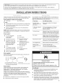
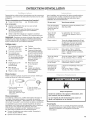
Remove parts package from the washer basket. Check that all
parts were included.
A B uC D
A. Front leveling feet with nuts (2) C. Drain hose
B. Shipping strap (not in parts bag. D. Silver double-wire hose clamp
See "Remove Shipping Strap")
Parts needed:
Check local codes and with gas supplier, check existing gas
supply, electrical supply and venting, and read "Electrical
Requirements," "Gas Supply Requirements," and "Venting
Requirements" before purchasing parts.
Mobile home installations require special parts (listed following)
available for purchase from the dealer from whom you purchased
your dryer. For further information, please reference the
"Assistance or Service" section of the Washer/Dryer User
Instructions.
[] Mobile Home Installation Kit. Ask for Part Number 346764.
[] Metal exhaust system hardware.
Your installation may require additional parts. For information on
ordering, please refer to the toll free phone numbers on the front
page of the Washer/Dryer User Instructions.
If You Have You Will Need to Buy
Laundry tub or Sump pump system (if not already
standpipe taller than available)
96" (2.4 m)
1" (25 mm) diameter 2" (51 mm) diameter to 1" (25 mm)
standpipe diameter standpipe adapter, Part
Number 3363920
Overhead sewer Standard 20 gal. (76 L) 34" (864 mm) tall
drain tub or utility sink and sump pump
(available from local plumbing suppliers)
Floor drain Siphon break, Part Number 285320,
additional drain hose, Part Number 285702
and connector kit, Part Number 285442
Drain hose too short Drain hose, Part Number 285664 and
connector kit, Part Number 285442
Lint clogged drain Drain protector, Part Number 367031
Water faucets 2 longer water fill hoses:
beyond reach of fill 6 ft (1.8 m) Part Number 76314,
hoses 10 ft (3.0 m) Part Number 350008
Explosion Hazard
Keep flammab(e materials and vapors, such as
gaso((ne, away from dryer.
Failure to do so can result in death, explosion, or fire.
You will need
[] A location that allows for proper exhaust installation. A gas
washer/dryer must be exhausted to the outdoors. See
"Venting Requirements."
[] A grounded electrical outlet located within 2 ft (610 mm) of
either side of the washer/dryer. See "Electrical Requirements."
[] A sturdy floor to support the washer/dryer weight (washer/
dryer, water, and load) of 500 Ibs (226.8 kg).
[] A level floor with a maximum slope of 1" (25 mm) under entire
washer/dryer. Clothes may not tumble properly and automatic
sensor cycles may not operate correctly if washer/dryer is not
level. Installing on carpet is not recommended.
3

[] Awaterheatersettodeliver120°F(49°C)watertothewasher.
[] Hotandcoldwaterfaucetslocatedwithin4ft(1.2m)ofthe
hotandcoldwaterfillvalves,andwater)ressureof5-100psi
(34.5-689.6kPa).
Thewasher/dryermustnotbeinstalledorstoredinanareawhere
itwillbeexposedtowaterand/orweather.
Donotoperateyourwasherintemperaturesatorbelow
32°F(0°C).Somewatercanremaininthewasherandcancause
damageinlowtemperatures.See"Washer/DryerCare"inthe
Washer/DryerUserInstructionsforwinterizinginformation.
Donotoperateyourdryerintemperaturesbelow45°F(7°C).At
lowertemperatures,thedryermightnotshutoffattheendofan
automaticcycle.Thiscanresultinlongerdryingtimes.
Checkcoderequirements.Somecodeslimit,ordonotpermit,
installationofthewasher/dryeringarages,closets,mobilehomes,
orsleepingquarters.Contactyourlocalbuildinginspector.
NOTE:Nootherfuel-burningappliancecanbeinstalledinthe
sameclosetasadryer.
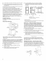
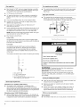
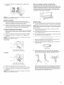
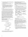
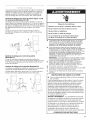
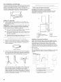
Installation Clearances
The location must be large enough to allow the dryer door
to open fully.
Washer/Dryer Dimensions
71%"
(1819 mm)
*Most installations require a minimum 5" (127 mm) clearance
behind the dryer for the exhaust vent with elbow. See "Venting
Requirements."
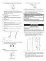
InstaBation spacing for recessed area or closet installation
The following spacing dimensions are recommended for this
washer/dryer. This washer/dryer has been tested for spacing of 0"
(0 mm) clearance on the sides. Recommended spacing should be
considered for the following reasons:
[] Additional spacing should be considered for ease of
installation and servicing.
[]
[]
Additional clearances might be required for wall, door,
and floor moldings.
Additional spacing on all sides of the washer/dryer
is recommended to reduce noise transfer.
For closet installation, with a door, minimum ventilation
openings in the top and bottom of the door are required.
Louvered doors with equivalent ventilation openings are
acceptable.
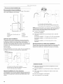
Oo°oO
ID I
m
1" 27' 1
(25rnm) (686ram) (25mm)
A
_- 6"
I # (152mrn)
48 in.2 -
(310cm2)
_]_ 24in.2-
__ (155cm2)
(25ram)(813ram) (127mm)
B C
m 31_
=_(76 rnm)
A. Recessed area
B. Side view - closet or confined area
C. Closet door with vents
*Required spacing
**Rear clearance may be 1" (25 mm) when house exhaust system
is lined up directly with dryer exhaust.
Mobile Home - Additional Installation Requirements
This washer/dryer is suitable for mobile home installations.
The installation must conform to the Manufactured Home
Construction and Safety Standard, Title 24 CFR, Part 3280
(formerly the Federal Standard for Mobile Home Construction and
Safety, Title 24, HUD Part 280) or Standard CAN/CSA-Z240 MH.
Mobile home installations require:
[] Metal exhaust system hardware, which is available for
purchase from your dealer.
[] Mobile Home Installation Kit Part Number 346764. See "Tools
and Parts" section for information on ordering.
Special provisions must be made in mobile homes to
introduce outside air into the dryer. The opening (such as a
nearby window) should be at least twice as large as the dryer
exhaust opening.
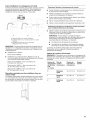
The washer/dryer can be installed using the standpipe drain
system (floor or wall), the laundry tub drain system, or the floor
drain system. Select the drain hose installation method you need.
See "Alternate Parts."
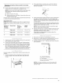
Standpipe drain system - wall or floor {views A & B)
The standpipe drain requires a minimum diameter standpipe of
2" (51 mm). The minimum carry-away capacity can be no less than
17 gal. (64 L) per minute. A 2" (51 mm) diameter to 1" (25 mm)
diameter standpipe adapter kit is available. See "Alternate Parts."
The top of the standpipe must be at least 39" (991 mm) high and no
higher than 96" (2.4 m) from the bottom of the washer.
A B
4

Laundry tub drain system (view C)
The laundry tub needs a minimum 20 gal. (76 L) capacity. The top
of the laundry tub must be at least 34" (864 mm) above the floor
and no higher than 96" (2.4 m) from the bottom of the washer.
Floor drain system (view D)
The floor drain system requires a siphon break that may be
purchased separately. See "Alternate Parts."
The siphon break must be a minimum of 28" (711 mm) from the
bottom of the washer. Additional hoses might be needed.
C D
[] Do not have a fuse in the neutral or ground circuit.
GROUNDING INSTRUCTIONS
[] For a grounded, cord-connected washer/dryer:
This washer/dryer must be grounded. In the event of
malfunction or breakdown, grounding will reduce the risk of
electric shock by providing a path of least resistance for
electric current. This washer/dryer is equipped with a cord
having an equipment-grounding conductor and a grounding
plug. The plug must be plugged into an appropriate outlet
that is properly installed and grounded in accordance with
all local codes and ordinances.
WARNING: Improper connection of the equipment-
grounding conductor can result in a risk of electric shock.
Check with a qualified electrician or service representative or
personnel if you are in doubt as to whether the washer/dryer
is properly grounded. Do not modify the plug provided with
the washer/dryer: if it wilt not fit the outlet, have a proper
outlet installed by a qualified electrician.
SAVE THESE INSTRUCTIONS
[]
[]
[]
[]
[]
Electrical Shock Hazard
Plug into a grounded 3 prong outlet.
Do not remove ground prong.
Do not use an adapter.
Do not use an extension cord.
Failure to follow these instructions can result in death,
fire, or electrical shock.
A 120 volt, 60 Hz., AC only, 15- or 20-amp, fused electrical
supply is required. A time-delay fuse or circuit breaker is
recommended. It is also recommended that a separate circuit
serving only this appliance be provided.
To minimize possible shock hazard, the cord must be plugged
into a mating, 3 prong, grounding-type outlet, grounded in
accordance with local codes and ordinances, if a mating
outlet is not available, it is the personal responsibility and
obligation of the customer to have the properly grounded
outlet installed by a qualified electrician.
IMPORTANT: The washer/dryer must be electrically grounded
in accordance with local codes, or in the absence of local
codes, with the National Electrical Code, ANSI/NFPA 70 or
with the Canadian Electrical Code, CSA C22.1.
If codes permit and a separate ground wire is used, it is
recommended that a qualified electrician determine that the
ground path is adequate.
Do not ground to a gas pipe.
Check with a qualified electrician if you are not sure the
washer/dryer is properly grounded.
Explosion Hazard
Use a new CSA International approved gas supply line.
Install a shut=off valve.
Securely tighten all gas connections.
if connected to LP, have a qualified person make sure
gas pressure does not exceed 13" (330 ram)water
column.
Examples of a qualified person include:
licensed heating personnel,
authorized gas company personnel, and
authorized service personnel.
Failure to do so can result in death, explosion, or fire.
Gas type
Natural Gas:
This washer/dryer is equipped for use with Natural gas. It is
design-certified by CSA international for LP (propane or butane)
gases with appropriate conversion.
[] Your washer/dryer must have the correct burner for the type of
gas in your home. Burner information is located on the rating
plate in the door well of your dryer. If this information does not
agree with the type of gas available, contact your dealer or call
the phone numbers referenced on the front page of the
Washer/Dryer User instructions.
LP gas conversion:
Conversion must be made by a qualified technician.
No attempt shall be made to convert the appliance from the gas
specified on the model/serial rating plate for use with a different
gas without consulting your gas company.

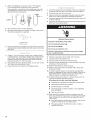
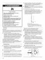
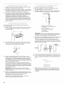
Gassupplyline
[] Must include 1/8"NPT minimum plugged tapping accessible
for test gauge connection, immediately upstream of the gas
connection to the washer/dryer (see illustration).
[]
[]
[]
[]
[]
[]
1/2" IPS pipe is recommended.
3/s"approved aluminum or copper tubing is acceptable for
lengths under 20 ft (6.1 m) if local codes and gas supplier
permit.
If you are using Natural gas, do not use copper tubing.
Lengths over 20 ft (6.1 m) should use larger tubing and a
different size adapter fitting.
Gas supply line coupling must be 34" (864 mm) to 37"
(940 mm) from the floor.
If your washer/dryer has been converted to use LP gas, 3/s"LP
compatible copper tubing can be used. If the total length of
the supply line is more than 20 ft (6.1 m), use larger pipe.
NOTE: Pipe-joint compounds that resist the action of LP gas
must be used. Do not use TEFLON ®*tape.
[] Must include a shutoff valve:
in the U.S.A.:
An individual manual shutoff valve must be installed within
six (6)feet (1.8 m) of the dryer in accordance with the National
Fuel Gas Code, ANSI Z223.1.
in Canada:
An individual manual shutoff valve must be installed in
accordance with the B149.1, Natural Gas and Propane
installation Code. it is recommended that an individual
manual shutoff valve be installed within six (6) feet (1.8 m)
of the dryer.
The location should be easy to reach for opening and closing.
A. Gas shutoff valve
B. 1/8"NPT plugged tapping
C. ½" NPT gas supply line
D. Gas supply fine coupling 34" (864 mm) min.
to 37" (940 mm) max. from floor
Burner input requirements
r
Elevations up to 10,000 ft (3,048 meters):
[] The design of this washer/dryer is certified by CSA
International for use at altitudes up to 10,000 ft (3,048 m)
above sea level at the Btu rating indicated on the model/serial
number plate. Burner input adjustments are not required when
the dryer is operated up to this elevation.
Elevations above 10,000 ft (3,048 meters):
[] When installed above 10,000 ft (3,048 m), a 4% reduction of
the burner Btu rating shown on the model/serial number plate
is required for each 1,000 ft (305 m) increase in elevation.
Gas supply pressure testing
[] The washer/dryer must be disconnected from the gas supply
piping system during pressure testing at pressures greater
than 1/2psi.
Dryer gas connection
[] This washer/dryer is equipped with its own permanent,
flexible gas connector, design-certified by CSA International,
for connecting the washer/dryer to the gas supply line.
Flexible gas connector
Fire Hazard
Use a heavy metal vent.
Do not use a p{ast}c vent.
Do not use a meta} fo[{ vent.
Fai{ure to fo{{ow these instructions can resu{t in death
or fire.
WARNING: To reduce the risk of fire, this washer/dryer
MUST BE EXHAUSTED OUTDOORS.
iMPORTANT: Observe all governing codes and ordinances.
The dryer exhaust must not be connected into any gas vent,
chimney, wall, ceiling, attic, crawlspace, or a concealed space
of a building.
r
if using an existing vent system
r
[] Clean lint from the entire length of the system and make sure
exhaust hood is not plugged with lint.
[] Replace any plastic or metal foil vent with rigid or flexible
heavy metal vent.
[] Review Vent system chart. Modify existing vent system if
necessary to achieve the best drying performance. Only
rigid or flexible metal vent shall be used for exhausting.
if this is a new vent system
Vent materia{
[] Use a heavy metal vent. Do not use plastic or metal foil vent.
1-%TEFLON is a registered trademark of E.I. Du Pont De Nemours and Company.
6

[] 4" (102 mm) heavy metal exhaust vent and clamps must be
used. DURASAFE TM venting products are recommended.
4" (102mm) heavymetalexhaust vent
DURASAFE TM vent products can be purchased from your
dealer or by calling Whirlpool Parts and Accessories. For more
information, see the "Assistance or Service" section of the
Washer/Dryer User Instructions.
Rigid metal vent
[] For best drying performance, rigid metal vents are
recommended.
[] Rigid metal vent is recommended to avoid crushing and
kinking.
Flexible metal vent
[] Flexible metal vents are acceptable only if accessible for
cleaning.
[]
[]
[]
[]
Flexible metal vent must be fully extended and supported
when the dryer is in its final location.
Remove excess flexible metal vent to avoid sagging and
kinking that may result in reduced airflow and poor
performance.
Do not install flexible metal vent in enclosed walls, ceilings,
or floors.
The total length of flexible metal vent should not exceed
73/4 ft (2.4 m).
Elbows
45° elbows provide better airflow than 90° elbows.
Good Bet_r
Clamps
[] Use clamps to seal all joints.
[] Exhaust vent must not be connected or secured with screws
or other fastening devices that extend into the interior of the
duct and catch lint. Do not use duct tape.
Clamp
Exhaust
Recommended hood styles are shown here.
B
(102 ram)
A.Louvered hood style
B.Box hood style
[]
[]
The angled hood style (shown here) is acceptable.
4 g_
(102 mm)_--_'_
V_ 21/2"
(64 mm)
An exhaust hood should cap the vent to keep rodents and
insects from entering the home.
Exhaust hood must be at least 12" (305 mm) from the ground
or any object that may be in the path of the exhaust (such as
flowers, rocks or bushes, snow line, etc.).
[] Do not use an exhaust hood with a magnetic latch.
improper venting can cause moisture and lint to collect
indoors, which may result in:
[] Moisture damage to woodwork, furniture, paint, wallpaper,
carpets, etc.
[] Housecleaning problems and health problems.
Excessive Weight Hazard
Use two or more people to move and install
washer/dryer.
Failure to do so can result in back or other injury.
To avoid floor damage, set washer/dryer onto cardboard before
moving across floor. Move washer/dryer close to its final location.
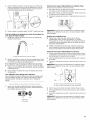
1. Do not cut yellow strap. Pull yellow strap firmly, until
completely removed from washer/dryer. There should be
2 cotter pins on the end of the shipping strap. Remove the
hang tag and pin from the vent pipe.
2. Tilt the washer/dryer forward. Move each of the 2 rear legs in
an up-down motion to check the self-adjusting leveling legs
for free movement. This is required for proper leveling. Gently
lower the washer/dryer to the floor.
3. Cut the shipping strap about 16" (406 mm) from the plug end.
Look for the words "CUT HERE." Discard end with cotter pins.
You will use the remaining piece of shipping strap to secure
the drain hose.

i diii:iii i:i iiiill¸iiii
install the front leveling feet
1. Prop up the front of the washer/dryer about 4" (102 mm) with
a wood block or similar object. The block needs to support
the weight of the washer/dryer.
2. Screw the Iocknut onto each foot to within 1" (25 mm) of the
base.
(25 ram)
3. Screw the feet into the correct holes at the front corner of the
washer/dryer until the nuts touch the washer.
NOTE: Do not tighten the nuts until the washer/dryer is level.
4. Tilt the washer/dryer back and remove the wood block. Gently
lower the washer/dryer to the floor.
For mobile home use
Washer/dryers with gas dryers must be securely fastened to the
floor.
Mobile home installations require a Mobile Home Installation Kit.
See "Tools and Parts" section for information on ordering.
Proper connection of the drain hose protects your floors from
damage due to water leakage. To keep the drain hose from
coming off or leaking, it must be installed according to the
following instructions:
IMPORTANT: To ensure proper installation, this procedure must
be followed exactly.
1. Check the drain hose to see whether it is the proper length.
2. Wet the inside of the straight end of the drain hose with tap
water.
IMPORTANT: Do not use any lubricant other than water.
3. Squeeze ears of the silver double-wire clamp with pliers to
open. Place clamp over the straight end of the drain hose
1A"(6.4 mm) from the end.
(6.4 mm)
4. Open clamp. Twist hose back and forth while pushing onto
drain connector on the side of the washer/dryer. Continue until
hose contacts the ribbed stops on the cabinet.
5. Place clamp over the area marked "CLAMR" Release clamp.
For laundry tub or standpipe drain systems
1. Make sure drain hose form is in correct position.
.........................................................
A.Drain hoseform
2. Put hooked end of drain hose into laundry tub or standpipe.
Rotate hook to eliminate kinks.
To keep drain water from going back into the washer:
[] Do not force excess drain hose into standpipe. Hose should
be secure but loose enough to provide a gap for air.
[] Do not lay excess hose on the bottom of the laundry tub.
For use with floor drain
Do not install the drain hose form onto the corrugated drain hose.
You may need additional parts. See Floor drain under "Tools and
Parts."
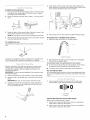
1= Insert a new flat washer into each end of the inlet hoses
(not provided). Firmly seat the washers in the couplings.
A B
A. Coupling
B. Washer
Connect the inlet hoses to the water faucets
Make sure the washer basket is empty.
1. Attach hose to the hot water faucet. Screw on coupling by
hand until it is seated on the washer.
2. Attach hose to the cold water faucet. Screw on coupling by
hand until it is seated on the washer.
8

3. Using pliers, tighten the couplings with an additional two-
thirds turn.
NOTE: Do not overtighten or use tape or sealants on the valve.
Damage to the valves can result.
Clear the water lines
[] Run water through both faucets and inlet hoses, into a
laundry tub, drainpipe, or bucket to get rid of particles in the
water lines that might clog the inlet valve screens.
[] Check the temperature of the water to make sure that the hot
water hose is connected to the hot water faucet and that the
cold water hose is connected to the cold water faucet.
Connect the inlet hoses to the washer
1. Attach the hot water hose to the bottom inlet valve. Attaching
the hot water hose first makes it easier to tighten connection
with pliers.
2. Screw on coupling by hand until it is seated on the washer.
3. Using pliers, tighten the couplings with an additional two-
thirds turn.
NOTE: Do not overtighten or use tape or sealants on the valve.
Damage to the valves can result.
In the U.S.A.
A. Cold water inlet valve (top)
B. Hot water inlet valve (bottom)
In Canada
A.Cold waterinlet valve(top)
B.Hot waterinlet valve(bottom)
4. Attach the cold water hose to the top inlet valve.
5. Screw on coupling by hand until it is seated on the washer.
6. Using pliers, tighten the couplings with an additional two-
thirds turn.
NOTE: Do not overtighten or use tape or sealants on the valve.
Damage to the valves can result.
if you are working in a closet or recessed area
Move the washer/dryer into its final location and remove
cardboard from under washer/dryer. Remove the access panel by
removing 3 Phillips-head screws and one bumper, located at the
top of the access panel. Set panel, screws, and bumper aside.
Complete hookup of water hoses. Replace access panel upon
completion of washer/dryer installation.
Check for leaks
[] Turn on the water faucets and check for leaks. A small amount
of water might enter the washer. You will drain this water later.
NOTE: Replace inlet hoses after 5 years of use to reduce the risk
of hose failure. Record hose installation or replacement dates for
future reference.
[] If you connect only one water hose, you must cap off the
remaining water inlet port.
[] Periodically inspect and replace hoses if bulges, kinks, cuts,
wear, or leaks are found.
[] The apparatus must be connected to the water faucets using
the new hoses. Do not use old hoses.
1. Move the washer/dryer to its final location and remove any
cardboard used to move the washer/dryer.
2. Locate the remaining piece of shipping strap. See "Remove
Shipping Strap."
3=
Shipping strap
Wrap the drain hose to the laundry tub leg or standpipe
with the shipping strap (A or B below). Push fastener into the
nearest hole in the shipping strap (see illustration above).
A B C
If the water faucets and the drain standpipe are recessed, put
the hooked end of the drain hose in the standpipe. Tightly
wrap the shipping strap around the water inlet hoses and the
drain hose (C above). Push fastener into the nearest hole in
the shipping strap (see illustration above).

Choose your exhaust installation type
Recommended exhaust installations
Typical installations vent the dryer from the rear of the washer/
dryer. Other installations are possible.
......................g
A ..............................................
k
........................
C ..................................................................................................................................ii!:"1- H
A. Dryer E.Elbow
B. Rigid metal or flexible metal vent F. Clamps
C. Clamps G. Elbow
D. Wall H. Exhaust hood
Optional exhaust installations
This washer/dryer can be converted to exhaust out the right
or left side. To convert the washer/dryer, use Side Exhaust Kit
Part Number 279823. If your washer/dryer was previously
exhausted from the right or left side, it can be converted to rear
exhaust by using standard offset connections. To cover the hole
in the side, one of the following plugs can be added:
692790 (white)
3977784 (biscuit)
Follow the instructions in the kit to install. Kits are available from
the dealer from whom you purchased your washer/dryer.
A B 0
A. Loop system with standard elbows
B. Loop system with one offset and one standard elbow
C. Vent system with one periscope (2" [51 mm] clearance)
NOTE: The following kits for close clearance alternate installations
are available for purchase. Please reference the "Assistance or
Service" section of the Washer/Dryer User Instructions.
[] Over-the-Top Installation:
Part Number 4396028
Periscope Installation (For use with dryer vent to wall vent
mismatch):
Part Number 4396037 - 0" (0 mm) to 18" (457 mm) mismatch
Part Number 4396011 - 18" (457 mm) to 29" (737 mm)
mismatch
Part Number 4396014 - 29" (737 mm) to 50" (1.27 m)
mismatch
Special provisions for mobile home installations
The exhaust vent must be securely fastened to a noncombustible
portion of the mobile home structure and must not terminate
beneath the mobile home. Terminate the exhaust vent outside.
A B C
A. Standard rear offset exhaust installation
B. Rear exhaust for offset close clearance connection
C. Left or right side exhaust installation
Alternate installations for close clearances
Venting systems come in many varieties. Select the type best for
your installation. Three close-clearance installations are shown.
Refer to the manufacturer's instructions provided with the vent
system.
Determine vent path
........................................................................................................................................................................................................................................................................................................r
[] Select the route that will provide the straightest and most
direct path outdoors.
[] Plan the installation to use the fewest number of elbows and
turns.
[] When using elbows or making turns, allow as much room
as possible.
[] Bend vent gradually to avoid kinking.
[] Use the fewest 90° turns possible.
10

Determine vent length and elbows needed for best drying
performance
[] Use the Vent system chart below to determine type of vent
material and hood combinations acceptable to use.
NOTE: Do not use vent runs longer than those specified in the
Vent system chart. Exhaust systems longer than those
specified will:
[] Shorten the life of the dryer.
[] Reduce performance, resulting in longer drying times and
increased energy usage.
The Vent system chart provides venting requirements that will help
to achieve the best drying performance.
Vent system chart
NOTE: Side exhaust installations add a 90° turn inside the dryer.
To determine maximum exhaust length, add one 90° turn to the
chart.
Number of Type of Vent Box or Angled
90° turns Louvered hoods
or elbows hoods
0 Rigid metal 37 ft (11.3 m) 35 ft (10.7 m)
1 Rigid metal 32 ft (9.7 m) 27 ft (8.2 m)
2 Rigid metal 24 ft (7.3 m) 19 ft (5.8 m)
1=
2.
3.
Install exhaust hood. Use caulking compound to seal exterior
wall opening around exhaust hood.
Connect vent to exhaust hood. Vent must fit inside exhaust
hood. Secure vent to exhaust hood with 4" (102 mm) clamp.
Run vent to dryer location. Use the straightest path possible.
See "Determine vent path" in "Plan Vent System." Avoid 90°
turns. Use clamps to seal all joints. Do not use duct tape,
screws, or other fastening devices that extend into the interior
of the vent to secure the vent, because they can catch lint.
Properly leveling your washer/dryer avoids excessive noise and
vibration.
1. Check the levelness of the washer/dryer by placing a level
on the top edge of the washer, first side to side, then front
to back.
2=
3=
4=
1=
2.
3=
If the washer/dryer is not level, prop up the front with the
wood block and adjust the feet up or down as necessary.
Remove wood block.
Tilt the washer/dryer forward until the rear of the washer/dryer
is at least 4" (102 mm) off the floor. You may hear the self-
adjusting rear feet click into place. Lower the washer/dryer to
the floor. Check the levelness of the washer/dryer with a level
as shown above.
If washer/dryer will not level, recheck rear leveling legs for free
movement as described in the "Install Leveling Legs" section.
Repeat until the washer/dryer is level.
NOTE: It may be necessary to level the washer/dryer again
after it is moved into its final location.
After the washer/dryer is in its final location and is level, use an
adjustable or open-end wrench to turn the nuts on the front
feet tightly against the washer cabinet.
If the nuts are not tight against the washer cabinet, the
washer/dryer may vibrate.
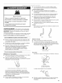
t :
Remove the red cap from the flexible gas connector.
Remove the 1/2"NPT adapter from the flexible gas connector
(it will be necessary to use two adjustable wrenches).
Install the adapter on the 1/2"rigid gas supply pipe using pipe-
joint compound.
A B......................_L_
A. ½" rigid gas supply pipe
B. Use pipe-joint compound.
C. _/2"NPT adapter
D. Do not use pipe-joint compound.
E. Flexible gas connector
NOTE: For LP gas connections, you must use pipe-joint
compound resistant to the action of LP gas. Do not use
TEFLON ®ttape.
1-(eTEFLON is a registered trademark of E.I. Du Pont De Nemours and Company.
11

4.
Attach the flexible gas connector to the 1/2"NPT adapter.
Do not use pipe-joint compound for this connection.
There should be a natural loop in the flexible gas connector.
The flexible gas connector must not be twisted, kinked, or
attached with any sharp bends.
CORRECT
WRONG
5. All connections must be wrench tightened.
6. Open the shutoff valve in the supply. The valve is open when
the handle is parallel to the gas pipe.
7.
A. Closed valve
B. Open valve
Test all connections by brushing on an approved noncorrosive
leak-detection solution. Bubbles will show a leak. Correct any
leak found.
1. Using a 4" (102 mm) clamp, connect vent to exhaust outlet
in washer/dryer. If connecting to existing vent, make sure the
vent is clean. The vent must fit over the exhaust outlet and
inside the exhaust hood. Make sure the vent is secured to
exhaust hood with a 4" (102 mm) clamp.
2. Move washer/dryer into its final location. Do not crush or kink
vent. Make sure washer/dryer is level.
3. Check that there are no kinks in the flexible gas line.
1. Check that all parts are now installed. If there is an extra part,
go back through the steps to see which step was skipped.
2. Check that you have all of your tools.
3. Dispose of/recycle all packaging materials. Keep the plastic
foam for use if the washer/dryer should be transported.
4. Check the washer/dryer's final location. Be sure the vent is not
crushed or kinked.
5. Check that the washer/dryer is level and front leveling feet are
tight. See "Level Washer/Dryer."
Electrical Shock Hazard
Plug into a grounded 3 prong outlet.
Do not remove ground prong.
Do not use an adapter.
Do not use an extension cord.
Failure to follow these instructions can result in death,
fire, or electrical shock.
6.
7.
8.
9.
Plug into a grounded 3 prong outlet. Turn on power.
Check that the water faucets are on.
Check for leaks around faucets and inlet hoses.
Remove the blue protective film on the console and any tape
remaining on the washer/dryer.
10. Read the Washer/Dryer User Instructions.
11. Wipe the dryer drum interior thoroughly with a damp cloth
to remove any dust.
12. To test the washer, measure 1/2the normal recommended
amount of detergent and pour it into the washer. Close the lid.
Select HEAVY DUTY and pull out the Cycle Control knob.
Allow the washer to complete one whole cycle.
13. To test the dryer, set the dryer on a full heat cycle (not an air
cycle) for 20 minutes and start the dryer.
if the dryer will not start, check the following:
14.
[] Washer/dryer is plugged into a grounded 3 prong outlet.
[] Start button has been firmly pushed.
[] Electrical supply is connected.
[] Household fuses are intact and tight, or circuit breakers
have not tripped.
[] Dryer door is closed.
When the dryer has been running for 5 minutes, open the
dryer door and feel for heat. If you do not feel heat, turn off the
dryer and check to see whether the gas supply line shutoff
valve is open.
[] Ifthe gas supply line shutoff valve is closed, open it, then
repeat the 5-minute test as outlined above.
[] Ifthe gas supply line shutoff valve is open, contact a
qualified technician.
12

SECURITEDELALAVEUSE/SECHEUSE
Votre securite et celle des autres est tres importante.
Nous donnons de nombreux messages de s6curit6 importants dans ce manuel et sur votre appareil m6nager. Assurez-vous de
toujours lire tousles messages de s6curit6 et de vous y conformer.
Voici le symbote d'alerte de s6curit6.
Ce symbole d'alerte de s6curit6 vous signale les dangers potentiels de d6c_s et de blessures graves &vous
et & d'autres.
Tous les messages de s6curit6 suivront le symbole d'alerte de s6curit6 et le mot "DANGER" ou
"AVERTISSEMENT". Ces mots signifient :
Risque possible de deces ou de blessure grave si vous ne
suivez pas immediaternent les instructions.
Risque possible de deces ou de blessure grave si vous
ne suivez pas les instructions.
Tousles messages de s6curit6 vous diront quel est le danger potentiel et vous disent comment r6duire le risque de blessure et
ce qui peut se produire en cas de non-respect des instructions.
AVERTISSEMENT - "Risque d'incendie"
- L'installation de la s_cheuse & linge dolt _tre effectu_e par un installateur qualifi_.
- installer la s_cheuse conform_rnent aux instructions du fabricant et au× codes Iocaux.
- Ne pas installer de s_cheuse h linge avec des rnat_riaux d'_vacuation en plastique
souple. Si un conduit rn6tallique souple (de type papier d'alurniniurn) est installS,
celui-ci dolt ¢tre d'un type sp_cifique identifi6 par le fabricant de I'appareil et
convenir & une utilisation avec les s_cheuses & linge, Les rnat_riau× d'_vacuation
souples sont connus pour s'affaisser, _tre facilement 6cras6s et bloquer la charpie.
Ces situations obstrueront le d_bit d'air de la s_cheuse h linge et augrnenteront le
risque d'incendie.
- Pour r6duire le risque de blessure grave ou de d_c_s, suivre routes
les instructions d'installation.
- Conserver ces instructions.
13

IMPORTANTES INSTRUCTIONS DE SECURITE
Avant de jeter ou de ranger votre vieille s6cheuse, enlever la porte.
CONSERVEZ CES INSTRUCTIONS
AVERTISSEMENT : Pour votre securite, les renseignements darts ce manuel doivent
_tre observes pour reduire au minimum les risques d'incendie ou d'e×plosion ou pour
eviter des dommages au produit, des blessures ou un deces.
- Ne pas entreposer ou utiliser de I'essence ou d'autres vapeurs ou iiquides
inflammables a pro×imite de cet appareil ou de tout autre appareil electromenager.
- QUE FAIRE DANS LE CAS D'UNE ODEUR DE GAZ :
• Ne pas tenter d'allumer un appareil.
• Ne pas toucher a un commutateur electrique; ne pas utiliser le telephone se trouvant
sur les lieu×.
= r_=vacuer tousles gens de la piece, de I'edifice ou du quartier.
= Appeler immediatement le fournisseur de gaz d'un telephone voisin. Suivre ses
instructions.
= A defaut de joindre votre fournisseur de gaz, appeler les pompiers.
- L'installation et l'entretien doivent _tre effectues par un installateur qualifie, une
agence de service ou le fournisseur de gaz.
AVERTISSEMENT : L'odorat ne permet pas toujours la detection d'une fuite de gaz.
Les distributeurs de gaz recommandent I'emploi d'un detecteur de gaz (homologation UL ou CSA).
Pour d'autre information, contacter le fournisseur de gaz local.
En cas de detection d'une fuite de gaz, executer les instructions "Que faire dans le cas d'une odeur de gaz".
iMPORTANT : L'installation du gaz dolt se conformer aux codes Iocaux, ou en I'absence de codes Iocaux, au code canadien
d'installation B149.1 du gaz naturel ou du propane.
La s6cheuse dolt _tre electriquement reli6e b,la terre conform6ment aux codes Iocaux, ou en I'absence de codes Iocaux, au Code
canadien de 1'61ectricit6, CSA C22.1.
14

INSTRUCTIONSD'INSTALLATION
Rassembler les outils et pieces n6cessaires avant de commencer
I'installation. Lire et suivre les instructions fournies avec les outils
indiqu6s ici.
Pi_ces n_cessaires pour la laveuse (non fournies) :
[] Tuyaux d'arriv6e d'eau [] Rondelles plates
Pour commander :
[] Appeler le marchand chez qui vous avez achet6
votre laveuse/s6cheuse.
[] Consulter le num6ro sans frais figurant sur la page
de couverture des Instructions pour I'utilisateur
de la laveuse/s6cheuse.
[] Visiter le site Web indiqu6 sur la page de couverture
des Instructions pour I'utilisateur de la laveuse/s6cheuse.
REMARQUE : Remplacer les tuyaux d'arriv6e d'eau apr_s 5 ans
d'utilisation pour r6duire le risque de d6faillance intempestive.
Prendre note de la date d'installation ou de remplacement des
tuyaux d'arriv6e d'eau, pour r6f6rence ult6rieure.
Outillage requis :
[] CI6 & molette b,manche []
de 8 ou 10" (pour le
[]
raccordement au gaz)
[]
[] Tournevis & lame plate
[] CI6 b.molette avec
ouverture jusqu'b. 1" []
(25 mm) ou cl6 plate de
%6" (pour ajuster les pieds
de la laveuse/s6cheuse)
[] Niveau
[] Tourne-6crou ou cl6 []
b.douille de 1¼,,
(recommand6) []
[] Bloc de bois
[]
(pour nivellement)
[] R_gle ou ruban &mesurer
Pi_ces fournies :
Couteau
Clapets d'6vacuation
Compos6 d'6tanch6it6
des tuyauteries r6sistant
au gaz de p6trole liqu6fi6
Pistolet #,calfeutrage et
compos6 de calfeutrage
(pour I'installation d'un
nouveau conduit
d'6vacuation)
Pince qui s'ouvre
19/16"(40 mm)
Ciseaux
Cisaille de ferblantier
(pour I'installation d'un
nouveau conduit
d'6vacuation)
Retirer le sachet de pieces du panier de la laveuse. V6rifier que
toutes les pieces de la liste sont pr6sentes.
A. Pieds de nivellement avant
avec dcrous (2)
B. Sangle d'expddition (non
incluse dans le sachet de
pi&ces. Voir "Enlever la sangle
d'expddition")
C. Tuyau de vidange
D. Bride de serrage argent,
deux ills
Pi_ces n6cessaires :
Consulter les codes Iocaux, v6rifier I'alimentation 61ectrique et
le conduit d'6vacuation existants, et consulter les sections
"Sp6cifications 61ectriques', "Alimentation en gaz" et "Exigences
concernant 1'6vacuation" avant d'acheter les pieces n6cessaires.
Les installations pour maison mobile n6cessitent des pieces
sp6cifiques (voir la liste suivante) disponibles chez le marchand
chez qui vous avez achet6 votre s6cheuse. Pour plus
d'informations, consulter la section "Assistance ou service"
des Instructions d'utilisation de la laveuse/s6cheuse.
[] Trousse d'installation pour maison mobile. Demander le
num6ro de piece 346764.
[] Syst_me d'6vacuation en m6tal.
Votre installation peut n6cessiter des pi_ces suppl6mentaires.
Pour commander, veuillez consulter les num6ros sans frais
d'interurbain sur la premiere page des Instructions pour
I'utilisateur de la laveuse/s6cheuse.
Si vous avez Vous devrez acheter
€:vier de buanderie
ou tuyau de rejet b.
I'_gout de plus de
96" (2,4 m)
Systeme de pompe de puisard (si non
d_ja disponible)
Tuyau de rejet
b.I'_gout de
1" (25 mm)
de diam6tre
Un adaptateur de 2" (51 mm) b,
1" (25 mm) de diam_tre, Piece n°
3363920
€:gout sur_lev_ Tuyau de vidange standard de 20 gal.
(76 L) de 34" (864 mm) de haut ou _vier
de d6charge et pompe de puisard
(disponibles chez les vendeurs de
materiel de plomberie Iocaux)
€:gout au plancher
Brise-siphon, Piece n° 285320,
tuyau de vidange suppl_mentaire,
Piece n° 285702 et kit de connexion,
Piece n° 285442
Tuyau de vidange Tuyau de vidange, Piece n° 285664 et
trop court kit de connexion, Piece n° 285442
€:vacuation bouch_e Dispositif de protection du systeme
par la charpie d'_vacuation, Piece n° 367031
Robinets d'eau
hors de port6e
des tuyaux de
remplissage
2 tuyaux de remplissage d'eau plus
longs :
6 pi (1,8 m), Piece n° 76314,
10 pi (3,0 m), Piece n° 350008
Risque d'explosJon
Garder les matieres et les vapeurs inflammables, telle
que I'essence, loin de la secheuse.
Le non-respect de cette instruction peut causer un
deces, une explosion ou un Jncendie.
II vous faudra
[] Un emplacement avec un conduit d'_vacuation appropri_.
Une laveuse/s_cheuse b,gaz dolt _tre dot6e d'un circuit de
d_charge b.I'ext_rieur. Voir "Exigences concernant
I'_vacuation'.
15

[]
[]
[]
[]
[]
Une prise 61ectrique avec liaison & la terre situ6e _,moins de
2 pi (610 ram) de I'un des cSt6s de la laveuse/s6cheuse. Voir
"Sp6cifications 61ectriques".
Un plancher robuste pour supporter le poids de la laveuse/
s6cheuse (laveuse/s6cheuse, eau et charge) de
500 Ib (226,8 kg).
Un plancher de niveau ayant une pente maximale de 1"
(25 mm) sous la laveuse/s6cheuse. Si la laveuse/s6cheuse
n'est pas d'aplomb, le linge peut ne pas culbuter
convenablement et les programmes command6s par des
d6tecteurs automatiques peuvent ne pas fonctionner
correctement. L'installation sur moquette n'est pas
recommand6e.
Un chauffe-eau qui fournit de I'eau & 120°F (49°C) & la
laveuse.
Des robinets d'eau chaude et d'eau froide situ6s & 4 pi (1,2 m)
des valves de remplissage d'eau chaude et d'eau froide, et
une pression d'eau de 5-100 Ib/po 2(34,5-689,6 kPa).
La laveuse/s6cheuse ne dolt pas _tre install6e ou remis6e dans
un endroit oQelle era expos6e & I'eau et/ou aux intemp6ries.
Ne pas faire fonctionner la laveuse & une temp@ature de 32°F
(0°C) ou moins. Un peu d'eau peut rester dans la laveuse et
causer des dommages & basses temp6ratures. Voir "Entretien de
la laveuse/s6cheuse" dans les Instructions pour I'utilisateur de la
laveuse/s6cheuse pour les renseignements sur I'hiv6risation.
Ne pas faire fonctionner la s6cheuse & des temp6ratures
inf6rieures & 45°F (7°C). A des temp@atures inf@ieures, la
s6cheuse risque de ne pas s'arr_ter & la fin d'un programme
automatique. Ceci risque de prolonger les dur6es de s6chage.
V6rifier les r_glements Iocaux. Certains codes limitent ou
n'autorisent pas I'installation de la laveuse/s6cheuse dans un
garage, un placard, une maison mobile ou une chambre 9,
coucher. Communiquer avec I'inspecteur des b&timents local.
REMARQUE •Aucun autre appareil & combustion ne dolt _tre
install6 dans le m_me placard que la s6cheuse.
Espacements d'instailation
L'emplacement dolt _tre assez grand pour permettre d'ouvrir
completement la porte de la s6cheuse.
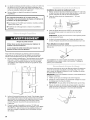
Dimensions de la laveuse/s_cheuse
71%"
(1819 mm)
- _!2 ¼"
(819 ram)
27"
(686ram)
*La plupart des installations requierent un espace minimum de
5" (127 mm) derriere la s6cheuse pour le conduit d'6vacuation
avec coude. Voir "Exigences concernant 1'6vacuation".
Espacement minimum pour une installation dans un
encastrement ou darts un placard
On recommande les dimensions d'espacement suivantes pour
cette laveuse/s6cheuse. Cette laveuse/s6cheuse a 6t6 test6e
pour une installation avec d6gagement de 0" (0 mm) sur les c6t6s.
L'espacement recommand6 dolt _tre consid6r6 pour les raisons
suivantes :
[] On pr6voira un peu plus d'espace pour faciliter I'installation
et I'entretien.
[]
[]
[]
Un espace suppl6mentaire peut _tre requis pour les moulures
de porte et de plancher et pour les plinthes.
Un espace suppl6mentaire de tous les c6t6s de la laveuse/
s6cheuse est recommand6 pour r6duire le transfert du bruit.
Pour installation dans un placard avec porte, on dolt pr6voir
des ouvertures minimum d'entr6e d'air en haut et en bas de
la porte. Les portes & claire-vole offrant des ouvertures
6quivalentes de passage de I'air sont acceptables.
OoooO
{D I
m
÷1P'----_t F-
1" 27" 1"
(25mm)(686mm)(25mm)
A
1"* 32.....
(25rnm)(813mm) (127mm)
](- (152mrn)
48po2 -
(310crn2)
24po2 -
(155ore2)
3"
f (76mm)
_. (76ram)
B C
A. Encastrement
B. Vue latdrale - placard ou endroit exigu
C. Porte de placard avec orifices d'entrde d'air
*Espacement requis
**Le d6gagement arriere peut _tre de 1" (25 mm) Iorsque le
systeme d'6vacuation du domicile est align6 directement avec
le conduit d'6vacuation de la s6cheuse.
Installation dans une maison mobile =autres exigences :
Cette laveuse/s6cheuse peut _tre install6e dans une maison
mobile. L'installation doit satisfaire les crit_res de la Manufactured
Home Construction and Safety Standard, Titre 24 CFR, partie
3280 (anciennement Federal Standard for Mobile Home
Construction and Safety, Titre 24 HUD, partie 280) ou de la Norme
CAN/CSA-Z240MH.
L'installation dans une maison mobile exige "
[] Systeme d'6vacuation en m6tal disponible chez votre
revendeur.
Ensemble d'installation pour maison mobile, piece num@o
346764. Voir la section "Outillage et pieces" pour plus
d'informations et pour commander.
II faut prendre des dispositions sp6ciales dans les maisons
mobiles pour I'apport d'air de I'ext6rieur dans la s6cheuse.
Uouverture (telle qu'une fen_tre & proximit6) devrait _tre au
moins deux fois plus grande que I'ouverture de d6charge de
la s6cheuse.
16

La laveuse/s6cheuse peut _tre install6e en utilisant le syst_me de
vidange avec tuyau de rejet & 1'6gout (au plancher ou mural), le
systeme de vidange avec 6vier de buanderie, ou le systeme de
vidange au plancher. Choisissez la m6thode d'installation du
tuyau de vidange dont vous avez besoin. Voir "Autres pieces".
Syst_rne de vidange avec tuyau de rejet a I'_gout = mural
ou au plancher {illustrations Aet B}
La vidange avec tuyau de rejet &1'6gout n6cessite un tuyau de
rejet & 1'6gout d'un diam_tre minimum de 2" (51 mm). La capacit6
minimum de vidange ne peut pas _tre de moins de 17 gal. (64 L)
par minute. Un adaptateur de 2" (51 mm) & 1" (25 mm) de diam_tre
est disponible pour le tuyau de rejet a 1'6gout. Voir "Autres
pieces".
Le dessus du tuyau de rejet & 1'6gout dolt _tre au moins
39" (991 mm) de hauteur et au maximum & 96" (2,4 m) du bas
de la laveuse.
39 I_
(991 mm)
B
Syst_rne de vidange avec _vier de buanderie
{illustration C)
L'6vier de buanderie n6cessite une capacit6 minimum de
20 gal. (76 L). Le dessus de 1'6vier de buanderie dolt _tre au moins
34" (864 mm) au-dessus du sol et au maximum & 96" (2,4 m)
du bas de la laveuse.
Syst_rne de vidange par le plancher {illustration D)
Le syst_me de vidange par le plancher n6cessite un brise-siphon
qui peut _tre achet6 s6par6ment. Voir "Autres pieces".
Le brise-siphon dolt _tre au moins & 28" (711 mm) du bas de la
laveuse. Des tuyaux suppl6mentaires peuvent _tre requis.
C D
Risque de choc electrique
Brancher sur une prise a 3 alveoles relJee a la terre.
Ne pas enlever la broche de liaison a la terre.
Ne pas utiliser un adaptateur.
Ne pas utiliser un c_ble de rallonge.
Le non-respect de ces instructions peut causer
un deces, un Jncendie ou un choc electrique.
L'appareil dolt _tre aliment6 uniquement par un circuit de
12OV CA, 60 Hz, 15 ou 20 amp@es, prot6g6 par fusible.
On recommande I'emploi d'un fusible ou d"un disjoncteur
temporis& II est 6galement recommand6 de raccorder
I'appareil sur un circuit distinct exclusif a cet appareil.
Pour minimiser les risques de choc 61ectrique, on dolt
brancher le cordon sur une prise de courant de configuration
correspondante, & 3 alv6oles, reli6e & la terre et install6e
conform6ment aux codes et r_glements Iocaux. Si une prise
de courant de configuration correspondante n'est pas
disponible, le client a la responsabll"it6 et I'obligation de faire
installer par un 61ectricien qualifi6 une prise de courant
correctement reli6e & la terre.
IMPORTANT : La laveuse/s6cheuse doit _tre reli6e &la terre
conform6ment aux codes Iocaux, ou en I'absence de codes
Iocaux, au Code canadien de 1'61ectricit6 CSA C22.1.
[] Si les codes le permettent et si on utilise un conducteur
distinct de liaison & la terre, il est recommand6 qu'un
_lectricien qualifi_ v_rifie la qualit_ de la liaison A la terre.
[] Ne pas relier & la terre &une canalisation de gaz.
[] Consulter un _lectricien qualifi_ en cas de doute sur la qualit_
de la liaison & la terre de/a laveuse/s_cheuse.
Ne pas avoir de fusible dans le circuit neutre ou de liaison
la terre.
INSTRUCTIONS DE LIAISON h. LATERRE
[] Pour une laveuse/s6cheuse reli6e & la terre et connect_e
par un cordon :
Cette laveuse/s_cheuse dolt _tre reli_e & la terre. En cas de
mauvais fonctionnement ou de panne, la liaison & la terre
r_duira le risque de choc 61ectrique en offrant au courant
_lectrique un acheminement d'_vacuation de moindre
r_sistance. Cette laveuse/s_cheuse est aliment6e par un
cordon _tectrique comportant un conducteur reli_ & la terre
et une fiche de branchement munie d'une broche de liaison &
la terre. La fiche dolt @re branch_e sur une prise appropri6e
qui est bien install_e et reli_e & la terre conform_ment &tous
les codes et r_gtements locaux.
AVERTISSEMENT " Le raccordement incorrect de
cet appareil au conducteur de liaison & ta terre peut susciter
un risque de choc 6tectrique. En cas de doute quant & la
qualit_ de liaison & la terre de la laveuse/s_cheuse, consulter
un _lectricien ou un technicien ou un personnel qualifi& Ne
pas modifier la fiche de branchement fournie avec la
laveuse/s6cheuse; si la fiche ne correspond pas & la
configuration de la prise de courant, demander & un
_lectricien qualifi_ d'instalter une prise de courant appropri_e.
CONSERVEZ CES INSTRUCTIONS
17

Risque d'explosion
Utiliser une canalisation neuve d'arrivee de gaz
approuv_e par CSA International.
Installer un robinet d'arr_t.
Bien setter chaque organe de connexion de la
canalisation de gaz.
En cas de connexion au gaz propane, demander b une
personne qualifi_e de s'assurer que la pression de gaz
ne d_passe pas 330 mm (13 po) de la colonne d'eau.
Par personne qualifi_e, on comprend :
le personnel autoris_ de chauffage,
le personnel autoris_ d'une compagnie de gaz, et
le personnel d'entretien autoris_.
Le non=respect de ces instructions peut causer
un d_ces, un explosion ou un incendie.
Type de gaz
Gaz naturel :
Cette laveuse/s6cheuse est 6quip_e pour une alimentation au gaz
naturel. Sa conception est homologu_e par CSA International
pour I'alimentation au gaz de p_trole liqu_fi6 (propane ou butane),
avec conversion appropri_e.
[] Cette laveuse/s_cheuse dolt _tre _quip_e du brOleur
convenable, correspondant au gaz sp_cifique qui alimente
I'habitation. L'information sur le brOleur se trouve sur la plaque
signal_tique dans le Iogement de la porte de la s_cheuse. Si
ces renseignements ne correspondent pas au type de gaz
disponible, contacter votre marchand ou composer les
num6ros de t_l_phone indiqu_s sur la page de couverture
des instructions d'utilisation de la laveuse/s_cheuse.
Conversion au gaz de p_trole liqu_fi_ :
Un technicien qualifi_ dolt effectuer la conversion.
Ne pas entreprendre de convertir I'appareil pour I'utilisation d'un
gaz different de celui indiqu_ sur la plaque signal_tique sans
d'abord consulter le fournisseur de gaz.
[]
[]
[]
[]
[]
[]
La canalisation dolt comprendre un connecteur obtur_
(filetage NPT de 1/8"ou plus) accessible pour le raccordement
de I'instrument de mesure imm_diatement en amont de la
connexion d'alimentation en gaz de la laveuse/s_cheuse
(voir I'illustration suivante).
Un tuyau IPS de 1/2"est recommand_.
Pour les Iongueurs inf_rieures a 20 pi (6,1 m), on peut utiliser
des tuyaux approuv_s de 3/8"(si les codes et le fournisseur
de gaz le permettent).
Pour le gaz naturel, ne pas utiliser de conduits en cuivre.
Pour les Iongueurs sup6rieures & 20 pi (6,1 m), on peut utiliser
des tuyaux plus gros et un adaptateur de grosseur diff_rente.
Le raccord d'accouplement de la canalisation de gaz dolt _tre
situ_ entre 34" (864 mm) et 37" (940 mm) au-dessus du sol.
18
[] Si la laveuse/s_cheuse a _t_ convertie au gaz de p6trole
liqu_fi_, on peut utiliser un tuyau en cuivre compatible au gaz
de p_trole liqu_fi_ de %". Si la Iongueur totale de la
canalisation d'arriv_e de gaz est sup_rieure & 20 pi (6,1 m),
utiliser une plus grosse conduite.
[] REMARQUE : On dolt utiliser un compos_ d'_tanch_it_ des
tuyauteries r_sistant & I'action du gaz propane. Ne pas utiliser
de ruban TEFLON ®_.
[] On dolt inclure un robinet d'arr6t"
Un robinet d'arr6t manuel individuel dolt 6tre install6
conform_ment aux prescriptions de la norme B149.1 (Code
canadien des installations &gaz naturel et & propane). On
recommande I'installation d'un robinet d'arr6t manuel
individuel & moins de six (6) pieds (1,8 m) de la s_cheuse.
L'emplacement dolt _tre facilement accessible pour
I'ouverture et la fermeture.
D
A. Robinet d'arr#t
B. Connecteur obtur_ (filetage NPT de 1/8")
C. Conduit d'alimentation en gaz (filetage NPT de ½")
D. Raccord d'accouplement de la canalisation de gaz
situ_ entre 34" (864 mm) min. et 37" (940 mm) max.
au-dessus du sol
F=xigencesconcernant I'alimentation du brQleur
Altitude ne d_passant pas 10 000 pi (3 048 m) :
[] La conception de cet appareil a 6t_ homologu_e par CSA
International pour I'utilisation jusqu'& une altitude de 10 000 pi
(3 048 m) au-dessus du niveau de lamer, pour le d_bit
thermique indiqu_ sur la plaque signal_tique. Aucun r_glage
du d_bit thermique du br01eur n'est n_cessaire Iorsque
I'appareil est utilis_ & une altitude inf_rieure & 10 000 pi
(3 048 m).
Altitude sup_rieure _ 10 000 pi (3 048 m} :
[] Lots de I'installation de I'appareil a une altitude sup_rieure &
10 000 pi (3 048 m), on constate une r_duction de 4 % du
d_bit thermique du br01eur indiqu6 sur la plaque signal_tique,
pour chaque tranche de 1 000 pi (305 m) d'altitude au-dessus
de 10 000 pi (3 048 m).
Tests de pressurisation de la canalisation de gaz
[] La laveuse/s_cheuse dolt _tre d_connect_e du syst_me
de canalisations d'alimentation en gas Iors de tout test de
pressurisation & des pressions plus _lev_es que 1/2Ib/po 2.
Raccordement de la s_cheuse &gaz
[] Cet appareil est fourni avec son propre raccord flexible pour
installation permanente (homologation CSA International),
pour le raccordement & la canalisation de gaz.
Raccord flexible
1XeTEFLONest une marque d_pos_ede E.I. Du Pont De Nemours et Compagnie

[] On recommande d'utiliser un conduit m6tallique rigide
pour r6duire les risques d'6crasement et de d6formation.
Risque d'incendie
Utiliser un conduit d'evacuation en metal Iourd.
Ne pas utiliser un conduit d'evacuation en plastique.
Ne pas utiliser un conduit d'evacuation en feuille
de metal.
Le non-respect de ces instructions peut causer
un deces ou un incendie.
Conduit m_tallique flexible
[] Les conduits m_talliques flexibles sont acceptables
seulement dans la mesure oOils sont accessibles en vue
du nettoyage.
[] Un conduit m_tallique flexible dolt &tre totalement d_ploy6
et soutenu Iorsque la s_cheuse est a sa position finale.
[] Enlever tout exc_s de conduit flexible pour _viter tout
affaissement ou d_formation susceptible de r6duire la
capacit_ d'_vacuation et le rendement.
[] Ne pas installer le conduit m_tallique flexible dans les cavit_s
ferm_es des murs, plafonds ou planchers.
[] La Iongueur totale du conduit m6tallique flexible ne dolt pas
d_passer 73/4pi (2,4 m).
Coudes
Les coudes & 45° permettent une meilleure circulation de I'air
que les coudes a 90°.
AVERTISSE_4ENT " Pour r_duire le risque d'incendie,
cette laveuse/s_cheuse dolt EVACUER L'AIR A L'EXTC:RIEUR.
IMPORTANT : Observer les dispositions de tous les codes et
r_glements en vigueur.
Le conduit d'_vacuation de la s_cheuse ne doit pas _tre connect6
&une _vacuation de gaz, une chemin_e, un mur, un plafond, un
grenier, un vide sanitaire ou un vide de construction.
En cas d'utilisation du syst_me d'bvacuation existant
[] Eliminer la charpie sur toute la Iongueur du systeme et veiller
ce que le clapet de d_charge ne soit pas obstru_ par une
accumulation de charpie.
[]
[]
Remplacer tout conduit de plastique ou de feuille m_tallique
par un conduit de m_tal Iourd rigide ou flexible.
Examiner le tableau de Iongueur du conduit d'_vacuation.
Apporter les modifications n_cessaires au systeme
d'_vacuation pour atteindre le meilleur rendement de
s_chage. Seul un conduit m_tallique rigide ou flexible
dolt _tre utilis_ pour 1'6vacuation.
En cas de nouveau syst_me d'6vacuation
Materiel pour 1'6vacuation
[] Utiliser un conduit d'_vacuation en m_tal Iourd. Ne pas utiliser
un conduit de plastique ou en feuille m_tallique.
[] Utiliser un conduit d'_vacuation en m_tal Iourd de 4"
(102 mm) et des brides de serrage. Les produits d'6vacuation
DURASAFE TM sont recommand_s.
Bon Meilleur
Brides de serrage
[] Utiliser des brides pour sceller tousles joints.
[] Le conduit d'_vacuation ne doit pas _tre connect_ ou fix_
avec des vis ou avec tout autre dispositif de serrage qui se
prolonge & I'int_rieur du conduit et peuvent retenir la charpie.
Ne pas utiliser de ruban adh_sif pour conduit.
Bride de serrage
Evacuation
Les styles de clapets recommand_s sont illustr6s ci-dessous.
B
(lO2ram)
A. Clapet apersiennes
B.Clapet de type bofte
Conduit d'_vacuation en m_tal Iourd de 4" (102 mm)
Le clapet inclin_ (illustr_ ici) est acceptable.
Les produits d'_vacuation DURASAFE TM peuvent _tre
obtenus chez votre marchand ou en appelant le service
Pieces et accessoires de Whirlpool. Pour plus d'information,
voir la section "Assistance ou service" des Instructions pour
I'utilisateur de la laveuse/s6cheuse.
Conduit m_tallique rigide
[] Pour un meilleur rendement de s_chage, on recommande
d'utiliser des conduits m_talliques rigides.
(102 m_(_
Terminer le conduit d'_vacuation par un clapet de d_charge
pour emp_cher les rongeurs et insectes d'entrer dans
I'habitation.
19

[]
[]
Le clapet de d6charge dolt _tre situ6 b,au moins 12" (305 mm)
au-dessus du sol ou de tout autre objet susceptible de se
trouver sur le trajet de Fair humide rejet6 (par exemple, fleurs,
roches ou arbustes, limite de la neige, etc.).
Ne pas utiliser un clapet d'6vacuation & fermeture
magn6tique.
Une mauvaJse evacuation de Fair peut causer de
I'humidite et une accumulation de charpJe a I'interieur de
la maison, ce qui peut provoquer :
[] Dommages par I'humidit6 aux boiseries, meubles, peinture,
papier-peint, tapis, etc.
[] Problemes de nettoyage dans lamaison et problemes
de sant&
Risque du poids e×cessJf
Utiliser deux ou plus de personnes pour deplacer et
installer la laveuse/secheuse.
Le non-respect de cette instruction peut causer une
blessure au dos ou d'autre blessure.
installation des pieds de nivellement avant
1. Relever I'avant de la laveuse/s6cheuse d'environ 4" (102 mm)
I'aide d'un bloc de bois ou autre objet similaire. Le bloc dolt
pouvoir supporter le poids de la laveuse/s6cheuse.
2. Visser le contre-6crou sur chaque pied a.1" (25 mm)
de la base.
3=
4=
1fl
(25rnrn)
......j
Visser les pieds dans les bons trous au coin avant de la
laveuse/s6cheuse jusqu'& ce que les 6crous touchent
la laveuse.
REMARQUE : Ne pas serrer les 6crous avant I'aplomb parfait
de la laveuse/s6cheuse.
Incliner la laveuse/s6cheuse vers I'arriere et retirer le bloc
de bois. Reposer doucement la laveuse/s6cheuse sur le sol.
Pour utilisation en maison mobile
Les laveuses/s6cheuses avec s6cheuses a.gaz doivent _tre bien
fix6s au sol.
Pour 6viter des dommages au plancher, placer la laveuse/
s6cheuse sur un carton avant de la d6placer sur le plancher.
Placer la laveuse/s6cheuse pros de son emplacement final.
1. Ne pas couper la sangle jaune. Tirer fermement sur la sangle
jaune pour I'enlever compl_tement de la laveuse/s6cheuse.
II devrait y avoir 2 goupilles fendues au bout de la sangle
d'exp6dition. Oter 1'6tiquette volante et la goupille du tuyau
de ventilation.
2. Incliner la laveuse/s6cheuse vers I'avant. Faire bouger chacun
des 2 pieds arriere vers le haut puis vers le bas pour v6rifier
que les pieds de nivellement auto-r6glables peuvent bouger
librement. Ceci est n6cessaire pour une mise b,niveau
correcte. Reposer doucement la laveuse/s6cheuse sur
le plancher.
3. Couper la sangle d'exp6dition b.environ 16" (406 mm)
du bout de la fiche. Rechercher les inscriptions "CUT HERE"
(COUPER ICI). Jeter le bout avec les goupilles fendues. Le
reste de la sangle d'exp6dition sert a.immobiliser le tuyau
de vidange.
Les installations en maison mobile n6cessitent un ensemble
d'installation pour maison mobile. Voir la section "Outillage et
pieces" pour commander.
Une bonne connexion du tuyau de vidange protege vos planchers
contre les dommages imputables _,une fuite d'eau. Pour 6viter
que le tuyau de vidange se d6tache ou fuie, I'installer en suivant
les instructions ci-dessous.
iMPORTANT : Pour une installation correcte, suivre attentivement
les 6tapes ci-dessous.
1. V6rifier que le tuyau de vidange a la bonne Iongueur.
2. Mouiller la surface int6rieure de I'extr6mit6 rectiligne du tuyau
de vidange avec de I'eau du robinet.
iMPORTANT : Ne pas utiliser de lubrifiant autre que de I'eau.
3. Presser les pattes de la bride de serrage argent & deux fils b,
I'aide d'une pince pour I'ouvrir. Placer la bride sur I'extr6mit6
droite du tuyau de vidange &1¼,,(6,4 mm) de I'extr6mit&
20
La page est en cours de chargement...
La page est en cours de chargement...
La page est en cours de chargement...
La page est en cours de chargement...
La page est en cours de chargement...
La page est en cours de chargement...
-
 1
1
-
 2
2
-
 3
3
-
 4
4
-
 5
5
-
 6
6
-
 7
7
-
 8
8
-
 9
9
-
 10
10
-
 11
11
-
 12
12
-
 13
13
-
 14
14
-
 15
15
-
 16
16
-
 17
17
-
 18
18
-
 19
19
-
 20
20
-
 21
21
-
 22
22
-
 23
23
-
 24
24
-
 25
25
-
 26
26


Maytag MGT3800TW - 27" Gas Laundry Center Guide d'installation
- Catégorie
- Laveuses sécheuses
- Taper
- Guide d'installation
- Ce manuel convient également à
dans d''autres langues
Documents connexes
-
Maytag YMET3800TW0 Guide d'installation
-
-
-
-
Maytag MGT3800XW Installation Instructions Manual
-
-
-
-
-
Whirlpool MGDX600XL0 Guide d'installation
Autres documents
-
Whirlpool YLTE5243DQB Guide d'installation
-
-
Bauknecht Gas Washer/Dryer Manuel utilisateur
-
-
Whirlpool WGTLV27FW0 Guide d'installation
-
Roper WGD Guide d'installation
-
-
-