ESAB MT-400 & MT-400EHD* Mig Welding Gun Troubleshooting instruction
- Catégorie
- Système de soudage
- Taper
- Troubleshooting instruction
Ce manuel convient également à

INSTRUCTIONS for
F-12-778-H
June, 1999
MT-200, MT-400 & MT-400EHD*
MIG WELDING GUN
WITH BAYONET CONNECTOR
Be sure this information reaches the operator.
You can get extra copies through your supplier.
These INSTRUCTIONS are for experienced operators. If you are not fully familiar with the principles of operation
and safe practices for arc welding equipment, we urge you to read our booklet, "Precautions and Safe Practices for
Arc Welding, Cutting and Gouging." Form 52-529. Do NOT permit untrained persons to install, operate, or maintain
this equipment. Do NOT attempt to install or operate this equipment until you have read and fully understand these
Instructions. If you do not fully understand these Instructions, contact your supplier for further information. Be
sure to read the Safety Precautions on page 3 before installing or operating this equipment.
*Extra Heavy Duty (EHD)

2
USER RESPONSIBILITY
This equipment will perform in conformity with the description thereof contained in this manual and accompany-
ing labels and/or inserts when installed, operated, maintained, and repaired in accordance with the instructions pro-
vided. This equipment must be checked periodically. Malfunctioning or poorly maintained equipment should not be
used. Parts that are broken, missing, worn, distorted, or contaminated should be replaced immediately. Should such
repair or replacement become necessary, the manufacturer recommends that a telephone or written request for
service advice be made to the Authorized Distributor from whom it was purchased.
This equipment or any of its parts should not be altered without the prior written approval of the manufacturer.
The user of this equipment shall have the sole responsibility for any malfunction which results from improper use,
faulty maintenance, damage, improper repair, or alteration by anyone other than the manufacturer or a service facility
designated by the manufacturer.
TABLE OF CONTENTS
I. INTRODUCTION
..........................................................................................................
5
1.1 Scope
.................................................................................................................
5
1.2 Features/Benefits
...............................................................................................
6
1.3 Required Equipment
..........................................................................................
6
1.4 Torch Accessory Guide & Selection
...................................................................
6
II. INSTALLATION
............................................................................................................
8
2.1 Torch Connections
.............................................................................................
8
2.1.1 Air-Cooled Models
.............................................................................................
8
III. OPERATION
.................................................................................................................
8
3.1 Operating Safety Precautions
............................................................................
8
3.2 Pre-Weld Requirements
....................................................................................
9
3.3 Welding Procedures
..........................................................................................
9
3.4 Shutdown Procedure
.........................................................................................
9
V SERVICE
......................................................................................................................
9
4.1 Service Procedure
.............................................................................................
9
4.2 Inspect and Service Torch Regularly
...............................................................
10
4.3 Nozzles
............................................................................................................
10
4.4 Wire Feed Liner (except 0.023-in. liner)
..........................................................
10
4.5 0.023-in. Wire Feed Liner
................................................................................
11
4.6 Curved Wire Guide
..........................................................................................
12
4.7 Torch Switch
....................................................................................................
13
4.8 Handle and Cable Assembly
............................................................................
13
V. REPLACEMENT PARTS
............................................................................................
13

3
SAFETY PRECAUTIONS
WARNING: These Safety Precautions are for
your protection. They summarize precaution-
ary information from the references listed in
Additional Safety Information section. Before
performing any installation or operating procedures, be
sure to read and follow the safety precautions listed below
as well as all other manuals, material safety data sheets,
labels, etc. Failure to observe Safety Precautions can result
in injury or death.
PROTECT YOURSELF AND OTHERS --
Some welding, cutting, and gouging
processes are noisy and require ear
protection. The arc, like the sun, emits
ultraviolet (UV) and other radiation and
can injure skin and eyes. Hot metal can cause burns.
Training in the proper use of the processes and equip-
ment is essential to prevent accidents. Therefore:
1. Always wear safety glasses with side shields in any work
area, even if welding helmets, face shields, and goggles
are also required.
2. Use a face shield fitted with the correct filter and cover
plates to protect your eyes, face, neck, and ears from
sparks and rays of the arc when operating or observing
operations. Warn bystanders not to watch the arc and
not to expose themselves to the rays of the electric-arc
or hot metal.
3. Wear flameproof gauntlet type gloves, heavy long-sleeve
shirt, cuffless trousers, high-topped shoes, and a weld-
ing helmet or cap for hair protection, to protect against
arc rays and hot sparks or hot metal. A flameproof apron
may also be desirable as protection against radiated
heat and sparks.
4. Hot sparks or metal can lodge in rolled up sleeves,
trouser cuffs, or pockets. Sleeves and collars should be
kept buttoned, and open pockets eliminated from the
front of clothing
5. Protect other personnel from arc rays and hot sparks
with a suitable nonflammable partition or curtains.
6. Use goggles over safety glasses when chipping slag or
grinding. Chipped slag may be hot and can fly far.
Bystanders should also wear goggles over safety glasses.
FIRES AND EXPLOSIONS -- Heat from
flames and arcs can start fires. Hot slag
or sparks can also cause fires and ex-
plosions. Therefore:
1. Remove all combustible materials well away from the
work area or cover the materials with a protective non-
flammable covering. Combustible materials include wood,
cloth, sawdust, liquid and gas fuels, solvents, paints and
coatings, paper, etc.
2. Hot sparks or hot metal can fall through cracks or
crevices in floors or wall openings and cause a hidden
smoldering fire or fires on the floor below. Make certain
that such openings are protected from hot sparks and
metal.“
3. Do not weld, cut or perform other hot work until the
workpiece has been completely cleaned so that there
are no substances on the workpiece which might pro-
duce flammable or toxic vapors. Do not do hot work on
closed containers. They may explode.
4. Have fire extinguishing equipment handy for instant use,
such as a garden hose, water pail, sand bucket, or
portable fire extinguisher. Be sure you are trained in its
use.
10/98
5. Do not use equipment beyond its ratings. For example,
overloaded welding cable can overheat and create a fire
hazard.
6. After completing operations, inspect the work area to
make certain there are no hot sparks or hot metal which
could cause a later fire. Use fire watchers when neces-
sary.
7. For additional information, refer to NFPA Standard 51B,
"Fire Prevention in Use of Cutting and Welding Pro-
cesses", available from the National Fire Protection Asso-
ciation, Batterymarch Park, Quincy, MA 02269.
ELECTRICAL SHOCK -- Contact with live
electrical parts and ground can cause
severe injury or death. DO NOT use AC
welding current in damp areas, if move-
ment is confined, or if there is danger of
falling.
1. Be sure the power source frame (chassis) is connected
to the ground system of the input power.
2. Connect the workpiece to a good electrical ground.
3. Connect the work cable to the workpiece. A poor or
missing connection can expose you or others to a fatal
shock.
4. Use well-maintained equipment. Replace worn or dam-
aged cables.
5. Keep everything dry, including clothing, work area, cables,
torch/electrode holder, and power source.
6. Make sure that all parts of your body are insulated from
work and from ground.
7. Do not stand directly on metal or the earth while working
in tight quarters or a damp area; stand on dry boards or
an insulating platform and wear rubber-soled shoes.
8. Put on dry, hole-free gloves before turning on the power.
9. Turn off the power before removing your gloves.
10. Refer to ANSI/ASC Standard Z49.1 (listed on next page)
for specific grounding recommendations. Do not mistake
the work lead for a ground cable.
ELECTRIC AND MAGNETIC FIELDS —
May be dangerous. Electric current flow-
ing through any conductor causes lo-
calized Electric and Magnetic Fields
(EMF). Welding and cutting current cre-
ates EMF around welding cables and
welding machines. Therefore:
1. Welders having pacemakers should consult their physi-
cian before welding. EMF may interfere with some pace-
makers.
2. Exposure to EMF may have other health effects which are
unknown.
3. Welders should use the following procedures to minimize
exposure to EMF:
A. Route the electrode and work cables together. Secure
them with tape when possible.
B. Never coil the torch or work cable around your body.
C. Do not place your body between the torch and work
cables. Route cables on the same side of your body.
D. Connect the work cable to the workpiece as close as
possible to the area being welded.
E. Keep welding power source and cables as far away
from your body as possible.

4
FUMES AND GASES -- Fumes and
gases, can cause discomfort or harm,
particularly in confined spaces. Do
not breathe fumes and gases. Shield-
ing gases can cause asphyxiation.
Therefore:
1. Always provide adequate ventilation in the work area by
natural or mechanical means. Do not weld, cut, or gouge
on materials such as galvanized steel, stainless steel,
copper, zinc, lead, beryllium, or cadmium unless positive
mechanical ventilation is provided. Do not breathe fumes
from these materials.
2. Do not operate near de-greasing and spraying opera-
tions. The heat or arc rays can react with chlorinated
hydrocarbon vapors to form phosgene, a highly toxic
gas, and other irritant gases.
3. If you develop momentary eye, nose, or throat irritation
while operating, this is an indication that ventilation is not
adequate. Stop work and take necessary steps to im-
prove ventilation in the work area. Do not continue to
operate if physical discomfort persists.
4. Refer to ANSI/ASC Standard Z49.1 (see listing below)
for specific ventilation recommendations.
5. WARNING: This product, when used for welding or
cutting, produces fumes or gases which
contain chemicals known to the State of
California to cause birth defects and, in
some cases, cancer. (California Health &
Safety Code
§25249.5 et seq.)
CYLINDER HANDLING -- Cylinders, if
mishandled, can rupture and violently
release gas. Sudden rupture of cylin-
der, valve, or relief device can injure or
kill. Therefore:
1. Use the proper gas for the process and use the proper
pressure reducing regulator designed to operate from
the compressed gas cylinder. Do not use adaptors.
Maintain hoses and fittings in good condition. Follow
manufacturer's operating instructions for mounting regu-
lator to a compressed gas cylinder.
2. Always secure cylinders in an upright position by chain
or strap to suitable hand trucks, undercarriages, benches,
walls, post, or racks. Never secure cylinders to work
tables or fixtures where they may become part of an
electrical circuit.
3. When not in use, keep cylinder valves closed. Have
valve protection cap in place if regulator is not con-
nected. Secure and move cylinders by using suitable
hand trucks. Avoid rough handling of cylinders.
4. Locate cylinders away from heat, sparks, and flames.
Never strike an arc on a cylinder.
5. For additional information, refer to CGA Standard P-1,
"Precautions for Safe Handling of Compressed Gases in
Cylinders", which is available from Compressed Gas
Association, 1235 Jefferson Davis Highway, Arlington,
VA 22202.
EQUIPMENT MAINTENANCE -- Faulty or
improperly maintained equipment can
cause injury or death. Therefore:
1. Always have qualified personnel perform the installa-
tion, troubleshooting, and maintenance work. Do not
perform any electrical work unless you are qualified to
perform such work.
2. Before performing any maintenance work inside a power
source, disconnect the power source from the incoming
electrical power.
3. Maintain cables, grounding wire, connections, power
cord, and power supply in safe working order. Do not
operate any equipment in faulty condition.
4. Do not abuse any equipment or accessories. Keep
equipment away from heat sources such as furnaces,
wet conditions such as water puddles, oil or grease,
corrosive atmospheres and inclement weather.
5. Keep all safety devices and cabinet covers in position
and in good repair.
6. Use equipment only for its intended purpose. Do not
modify it in any manner.
ADDITIONAL SAFETY INFORMATION -- For
more information on safe practices for elec-
tric arc welding and cutting equipment, ask
your supplier for a copy of "Precautions and
Safe Practices for Arc Welding, Cutting and
Gouging", Form 52-529.
The following publications, which are available from the
American Welding Society, 550 N.W. LeJuene Road, Mi-
ami, FL 33126, are recommended to you:
1. ANSI/ASC Z49.1 - "Safety in Welding and Cutting"
2. AWS C5.1 - "Recommended Practices for Plasma Arc
Welding"
3. AWS C5.2 - "Recommended Practices for Plasma Arc
Cutting"
4. AWS C5.3 - "Recommended Practices for Air Carbon
Arc Gouging and Cutting"
5. AWS C5.5 - "Recommended Practices for Gas Tungsten
Arc Welding“
6. AWS C5.6 - "Recommended Practices for Gas Metal Arc
Welding"“
7. AWS SP - "Safe Practices" - Reprint, Welding Hand-
book.
8. ANSI/AWS F4.1, "Recommended Safe Practices for
Welding and Cutting of Containers That Have Held
Hazardous Substances."
MEANING OF SYMBOLS - As used through-
out this manual: Means Attention! Be Alert!
Your safety is involved.
Means immediate hazards which, if
not avoided, will result in immediate,
serious personal injury or loss of life.
Means potential hazards which could
result in personal injury or loss of life.
Means hazards which could result in
minor personal injury.
SP98-10
SAFETY PRECAUTIONS

5
tibles du secteur où lon exécute des soudures ou des
coupes à larc, à moins de les recouvrir complètement
dune bâche non-inflammable. Ce type de matériaux
comprend notamment le bois, les vêtements, la sciure,
lessence, le kérosène, les peintures, les solvants, le
gaz naturel, lacétylène, le propane et autres sub-
stances combustibles semblables.
b. Les étincelles ou les projections de métal incandes-
cent peuvent tomber dans des fissures du plancher ou
dans des ouvertures des murs et y déclencher une
ignition lente cachée. Veiller à protéger ces ouvertures
des étincelles et des projections de métal.
c. Nexécutez pas de soudures, de coupes, dopérations
de gougeage ou autres travaux à chaud à la surface
de barils, bidons, réservoirs ou autres contenants
usagés, avant de les avoir nettoyés de toute trace de
substance susceptible de produire des vapeurs
inflammables ou toxiques.
d. En vue dassurer la prévention des incendies, il
convient de disposer dun matériel dextinction prêt à
servir immédiatement, tel quun tuyau darrosage, un
seau à eau, un seau de sable ou un extincteur portatif.
e. Une fois le travail à larc terminé, inspectez le secteur
de façon à vous assurer quaucune étincelle ou projec-
tion de métal incandescent ne risque de provoquer
ultérieurement un feu.
3. CHOC ÉLECTRIQUE-- Le gougeage à larc et à larc
au plasma exige lemploi de tensions à vide relativement
importantes; or, celles-ci risquent de causer des
dommages corporels graves et même mortels en cas
dutilisation inadéquate. La gravité du choc électrique
reçu dépend du chemin suivi par le courant à travers le
corps humain et de son intensité.
a. Ne laissez jamais de surfaces métalliques sous ten-
sion venir au contact direct de la peau ou de vêtements
humides. Veillez à porter des gants bien secs.
b. Si vous devez effectuer un travail sur une surface
métallique ou dans un secteur humide, veillez à assu-
rer votre isolation corporelle en portant des gants secs
et des chaussures à semelles de caoutchouc et en
vous tenant sur une planche ou une plate-forme
sèche.
c. Mettez toujours à la terre le poste de soudage/coupage
en le reliant par un câble à une bonne prise de terre.
d. Nutilisez jamais de câbles usés ou endommagés. Ne
surchargez jamais le câble. Utilisez toujours un
équipement correctement entretenu.
e. Mettez léquipement hors tension lorsquil nest pas en
service. une mise à la masse accidentelle peut en effet
provoquer une surchauffe de léquipement et un dan-
ger dincendie. Ne pas enrouler ou passer le câble
autour dune partie quelconque du corps.
f. Vérifiez si le câble de masse est bien relié à la pièce en
un point aussi proche que possible de la zone de
travail. Le branchement des câbles de masse à
lossature du bâtiment ou en un point éloigné de la
zone de travail augmente en effet le risque de pas-
sage dun courant de sortie par des chaînes de
PRÉCAUTIONS DE SÉCURITÉ
AVERTISSEMENT: Ces règles de sécurité ont pour objet
d assurer votre protection. Veillez à lire et à observer les
précautions énoncées ci-dessous avant de monter l
équipement ou de commercer à lutiliser. Tout défaut
dobservation de ces précautions risque dentraîner des
blessures graves ou mortelles.
1. PROTECTION INDIVIDUELLE-- Les brûlures de la
peau et des yeux dues au rayonnement de larc
électrique ou du métal incandescent, lors du soudage
au plasma ou à lélectrode ou lors du gougeage à
larc, peuvent savérer plus graves que celles résultant
dune exposition prolongée au soleil. Aussi convient-il
dobserver les précautions suivantes:
a. Portez un écran facial adéquat muni des plaques
protectrices et des verres filtrants appropriés afin de
vous protéger les yeux, le visage, le cou et les oreilles
des étincelles et du rayonnement de larc électrique
lorsque vous effectuez des soudures ou des coupes
ou lorsque vous en observez lexécution.
AVERTISSEZ les personnes se trouvant à proximité
de façon à ce quelles ne regardent pas larc et à ce
quelles ne sexposent pas à son rayonnement, ni à
celui du métal incandescent.
b. Portez des gants ignifugés à crispins, une tunique
épaisse à manches longues, des pantalons sans
rebord, des chaussures à embout dacier et un casque
de soudage ou une calotte de protection, afin déviter
dexposer la peau au rayonnement de larc électrique
ou du métal incandescent. ll est également souhaitable
dutiliser un tablier ininflammable de façon à se
protéger des étincelles et du rayonnement thermique.
c. Les étincelles ou les projections de métal incandes-
cent risquent de se loger dans des manches
retroussées, des bords relevés de pantalons ou dans
des poches. Aussi convient-il de garder boutonnés le
col et les manches et de porter des vêtements sans
poches à lavant.
d. Protégez des étincelles et du rayonnement de larc
électrique les autres personnes travaillant à proximité
à laide dun écran ininflammable adéquat.
e. Ne jamais omettre de porter des lunettes de sécurité
lorsque vous vous trouvez dans un secteur où lon
effectue des opérations de soudage ou de coupage à
larc. Utilisez des lunettes de sécurité à écrans ou
verres latéraux pour piquer ou meûler le laitier. Les
piquetures incandescentes de laitier peuvent être
projetées à des distances considérables. Les
personnes se trouvant à proximité doivent également
porter des lunettes de protection.
f. Le gougeage à larc et le soudage à larc au plasma
produisent un niveau de bruit extrêmement élevé (de
100 à 114 dB) et exigent par conséquent lemploi de
dispositifs appropriés de protection auditive.
2. PRÉVENTION DES INCENDES-- Les projections de
laitier incandescent ou détincelles peuvent provoquer
de graves incendies au contact de matériaux com-
bustibles solides, liquides ou gazeux. Aussi faut-il
observer les précautions suivantes:
a. Éloigner suffisamment tous les matériaux combus-
9/97

6
levage, des câbles de grue ou divers chemins
électriques.
g. Empêchez lapparition de toute humidité, notamment
sur vos vêtements, à la surface de lemplacement de
travail, des câbles, du porte-électrode et du poste de
soudage/coupage. Réparez immédiatement toute fuite
deau.
4. VENTILATION-- La respiration prolongée des fumées
résultant des opérations de soudage/coupage, à
lintérieur, dun local clos, peut provoquer des mal-
aises et des dommages corporels. Aussi convient-il
dobserver les précautions suivantes:
a. Assurez en permanence une aération adéquate de
lemplacement de travail en maintenant une ventila-
tion naturelle ou à laide de moyens mécaniques.
Neffectuez jamais de travaux de soudage ou de
coupage sur des matériaux de zinc, de plomb, de
beryllium ou de cadmium en labsence de moyens
mécaniques de ventilation capables dempêcher
linhalation des fumées dégagées par ces matériaux.
b. Neffectuez jamais de travaux de soudage ou de
coupage à proximité de vapeurs dhydrocarbure chloré
résultant dopérations voisines de dégraissage ou de
pulvérisation. La chaleur dégagée ou le rayonnement
de larc peut déclencher la formation de phosgène --
gaz particulièrement toxique -- et dautres gaz irri-
tants, à partir des vapeurs de solvant.
c. Une irritation momentanée des yeux, du nez ou de la
gorge constatée au cours de lutilisation de
léquipement dénote un défaut de ventilation. Arrêtez-
vous de travailler afin de prendre les mesures néces-
saires à lamélioration de la ventilation. Ne poursuivez
pas lopération entreprise si le malaise persiste.
d. Certaines commandes comportent des canalisations
où circule de lhydrogène. Larmoire de commande est
munie dun ventilateur destiné à empêcher la forma-
tion de poches dhydrogène, lesquelles présentent un
danger dexplosion; ce ventilateur ne fonctionne que
si linterrupteur correspondant du panneau avant se
trouve placé en position ON (Marche). Veillez à
manuvrer cette commande en vérifiant si le couvercle
est bien en place, de façon à assurer lefficacité de la
ventilation ainsi réalisée. Ne jamais débrancher le
ventilateur.
e. Les fumées produites par lopération de soudage ou
de coupage peuvent savérer toxiques. Aussi est-il
nécessaire de disposer en permanence dun dispositif
adéquat de ventilation de type aspirant, afin délimi-
ner du voisinage de lopérateur tout dégagement de
fumée visible.
f. Consultez les recommandations particulières en matière
de ventilation indiquées à lalinéa 6 de la norme Z49.1
de lAWS.
5. ENTRETIEN DE LÉQUIPEMENT-- Un équipement
entretenu de façon défectueuse ou inadéquate risque
non seulement de réaliser un travail de mauvaise
qualité mais, chose plus grave encore, dentraîner des
dommages corporels graves, voire mortels en
déclenchant des incendies ou des chocs électriques.
Observez par conséquent les précautions suivantes:
a. Efforcez-vous de toujours confier à un personnel qua-
lifié linstallation, le dépannage et lentretien du poste
de soudage et de coupage. Neffectuez aucune
réparation électrique sur léquipement à moins dêtre
qua-lifié à cet effet.
b. Ne procédez jamais à une tâche dentretien quelconque
à lintérieur du poste de soudage/coupage, avant
davoir débranché lalimentation électrique.
c. Maintenez en bon état de fonctionnement les câbles,
le câble de masse, les branchements, le cordon
dalimentation et le poste de soudage/coupage.
Nutilisez jamais le poste ou léquipement sil présente
une défectuosité quelconque.
d. Prenez soin du poste de soudage et de coupage et des
équipements accessoires. Gardez-les à lécart des
sources de charleur, notamment des fours, de
lhumidité, des flaques deau maintenez-les à labri des
traces dhuile ou de graisse, des atmosphères corro-
sives et des intempéries.
e. Laissez en place tous les dispositifs de sécurité et tous
les panneaux de larmoire de commande en veillant à
les garder en bon état.
f. Utilisez le poste de soudage/coupage conformément à
son usage prévu et neffectuez aucune modification.
6. INFORMATIONS COMPLÉMENTAIRES RELATIVES
À LA SÉCURITÉ--
Pour obtenir des informations complémentaires sur les
règles de sécurité à observer pour le montage et
lutilisation déquipements de soudage et de coupage
électriques et sur les méthodes de travail
recommandées, demandez un exemplaire du livret N°
52529 Precautions and Safe Practices for Arc Weld-
ing, Cutting and Gouging publié par ESAB. Nous
conseillons également de consulter les publications
sui-vantes, tenues à votre disposition par lAmerican
Welding Society, 550 N.W. LeJuene Road, Miami, FL
32126:
a. Safety in Welding and Cutting AWS Z49.1
b. Recommended Safe Practices for Gas-Shielded Arc
Welding AWS A6. 1.
c. Safe Practices for Welding and Cutting Containers
That Have Held Combustibles AWS-A6.0.
d. Recommended Safe Practices for Plasma Arc Cutting
AWS-A6. 3.
e. Recommended Safe Practices for Plasma Arc Weld-
ing AWS-C5. 1.
f. Recommended Safe Practices for Air Carbon Arc
Gouging and Cutting AWS-C5. 3.
g. Code For Safety in Welding and Cutting CSA-Standard
W117. 2.
9/97
PRÉCAUTIONS DE SÉCURITÉ

7
I. INTRODUCTION
1.1 SCOPE
This manual provides installation, operation, service
and parts information for the MT-200, MT-400 and MT-
400EHD air-cooled welding torch with bayonet type
connector for connecting to Mig-35 and Digimig. For
information on the equipment with which the torch is
used, such as power sources and wire feeders, refer
to the instruction manuals for that equipment.
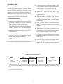
1.2 FEATURES/BENEFITS
l assembles or packages available - the MT-200,
MT-400 "ready-to-weld" torch comes ready to hook
up to the Mig 35 or Digimig Wire Feeder.
—or, the MT-400 EHD torch packages which in-
clude unassembled liner, heavy duty contact tip(s)
or tube(s), and extra-heavy duty threaded nozzle.
l lightweight extended performance - see Specifi-
cation Table 1.1.
l self-insulated slide-on nozzle design - one piece
design with insulator firmly crimped inside the
nozzle is less susceptible to burn-up.
—or, heavy-duty threaded nozzles that extend ca-
pacity.
l two-piece tip adaptor - reduces consumable costs
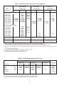
TABLE 1.1 Torch Specifications
(a) The MT-400 EHD torch uses HD (Heavy Duty) tips or tubes and EHD (Extra Heavy Duty) threaded nozzles to increase
current capacity to 500 amps. Using these accessories will increase the capacity of any MT-400 torch to 500 amps (see Fig.
1.4).
* @ 60% duty cycle (10 min. base)
Rated Current Capacity* Wire Sizes Available
Model CO2 Mixed Gases Accommodated Lengths
MT-200 300 amps 200 amps .023" to 1/16" 10', 12' or 15'
MT-400 400 amps 275 amps .023" to 3/32" 10', 12', 15' or 25'
MT-400 EHD 500 amps 375 amps .035" to 3/32" 15' (a)
l heavy duty torque crimped cable design - elimi-
nates premature failure of soldered cables due to
constant flexing and subsequent work hardening
and breakage of copper conductor strands.
l contact tips, or heavy-duty contact tubes - many
of which are interchangeable with the MT-200 and
MT-400 models.
l rugged, one piece composite cable assembly-
strong lightweight and easy to manipulate,
providing outstanding comfort and flexibility weld-
ers demand.
l flame retardant design - self-extinguishing ma-
terial of high impact resistance for long life and
durability.
l enclosed torch micro-switch - provides sure long
life for millions of cycles; because the micro-switch
is enclosed, no manual cleaning of exposed con-
tacts is required to keep the torch working.
l reversible torch screw - enables welder to change
the trigger location (top or bottom) to the position
of his choice.
l "easy fix" design - thread-in wire guide, slide to-
gether trigger housing, and replaceable one-piece
handle and cable assembly, allowing for quick and
easy repair.

8
TABLE 1.2 Basic Torch Assemblies Available (see Fig. 5.1)*
* Basic torches do not include liners, contact tips/tubes, or nozzles. Mix and match the accessories listed in Fig. 1.4 and
Tables 1.4.1, 1.4.2, and 1.4.3 to customize a torch for your welding application.
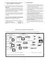
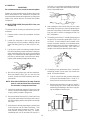
1.3 REQUIRED EQUIPMENT (See Fig. 1.3)
1.3.1 Wire Feeder Connector Assembly - P/N
2075378
Provides quick connect and disconnect of the
MT-200 or MT-400 to a MIG-35, or Digimig Wire
Basic Assy./Length 10-ft. (3.0m) 12-ft. (3.6m) 15-ft. (4.5m) 25-ft. (7.5m)
MT-200 998888 948921 998887 ---
MT-400 999469 948922 999470 18232
Feeder. It includes power cable, gas hose, and
switch cord with fitted connections.
1.3.2. Wire Outlet Guide and Feed Roll
Select the proper outlet guide and feed roll from
Table 1.3.
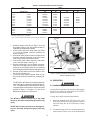
Table 1.3 - Outlet Guide to Feed Roll
Wire Wire Outlet Guide Feed Roll (U-, V-, or Serrated Groove)
Wire Size MIG-35 MIG-35
Type In. Digimig Digimig
Hard 0.023 999745n 17998(V)
H 0.030 993860(a) 2075300(V)
0.035 993860(a) 2075303(V)
0.045 39N15(b) 2075302(V)
0.052 39N15(b) 2075330(V)
1/16 39N15(b) 2075299(V)
Cored 0.035 9933860(a) 19761 (Serr.)
"C" 0.045 39N15(b) 19761 (Serr.)
0.052 39N15(b) 2075261 (Serr.)
1/16 39N15(b) 2075261 (Serr.)
5/64 62N17(c) 2075261 (Serr.)
3/32 62N17(c) 2075257 (Serr.)
Soft 0.035 29N13(d) 2075304 (U)
"S" 3/64 29N13(d) 2075301 (U)
n Also requires Guide Bushing, P/N 17997 (see Fig. 1.3).
(a) Includes replaceable sleeve (995651).
(b) Includes replaceable sleeve (995692).
(c) Requires outlet guide insert (993902 - yellow for 0.035-in.; 05N57 - red for 3/64-in.)
MIG-35, DIGIMIG
using 0.023-in. wire (MT-200)
OUTLET GUIDE - 999745
INCLUDES INSERT - 999746
(CUT TO LENGTH)
(See Table 1.3 or
Wire Feeder booklet)
Figure 1.3 - Connecting MT-200 or MT-400 to a Mig-35 or Digimig Wire Feeder

9
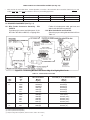
1.4 TORCH ACCESSORY GUIDE & SELECTION -
Fig. 1.4, & Tables 1.4.1, 1.4.2 and 1.4.3.
Standard Duty Tips and Nozzles provide good perfor-
mance and service life for the majority of welding
applications.
Heavy Duty Tips, Tubes and Nozzles improve the per-
formance and extend the service life when used with
high current applications, high spatter wires, pulsed arc
mig and when used in confined areas.
Extra Heavy Duty (brass) Slide-on Nozzles provide
improved service life when subjected to extreme im-
pact abuse.
Extra Heavy Duty Threaded Nozzles and Heavy Duty
Tips and Tubes extend the rating of the MT-400 from
400 amps to 500 amps @ 60% duty cycle.
Accessory Selection - Assembly Guide .. see Fig. 1.4
Contact Tips and Tubes .................... see Table 1.4.1
Nozzles (slip-on or threaded) ............ see Table 1.4.2
Liners ............................................... see Table 1.4.3
Figure 1.4 Accessories Selection - Assembly Guide
To select correct accessories, choose tip based on wire and follow Guide Chart to determine nozzle and adaptors.
CONTACT TIPS
AND TUBES
STANDARD DUTY CONTACT TIPS
ADAPTORS
NOZZLES
SLIDE ON SELF INSULATED NOZZLES
MT-200
MT-400
STANDARD DUTY
SEE TABLE
1.4.1
FOR PART
NUMBERS
.023" M or L .052" S or M
.030" M or L 1/16" S or M
.035" M or L 5/64" S or M
.045" - 3/64" S, M or L
SHORT (S)
MEDIUM (M)
LONG (L)
SEE TABLE
1.4.1
FOR PART
NUMBERS
#6 TAPERED #12
#8 #12 SPOT
#10
EXTRA HEAVY
DUTY
HEAVY DUTY
#8
#10
#12
#12 SPOT
#12 BRASS
STANDARD ACCESSORIES
SEE TABLE
1.4.2
FOR PART
NUMBERS
HEAVY DUTY CONTACT TIPS
EXTRA HEAVY DUTY
THREADED NOZZLES
SHORT (S)
MEDIUM (M)
.045" - 3/64" M 1/16" M
.052"M 5/64" M
3/32" M
SEE TABLE
1.4.1
FOR PART
NUMBERS
HEAVY DUTY CONTACT TUBES
SHORT (S)
MEDIUM (M)
.035" M 1/16" M
.045" - 3/64" M 5/64" S
.052" M 3/32" S
SEE TABLE
1.4.2
FOR PART
NUMBERS
#8
#10
#12
#16 SPOT
P/N 948785
P/N 17766 (.045" - 1/16")
P/N 948786 (5/64" - 3/32")
P/N 17135
P/N 17136
P/N 17154
P/N 17318
P/N 948793
COLLET BODY
COLLET
PRIMARY USE OF ACCESSORIES
ALTERNATE USE OF ACCESSORIES
ACCESSORIES FOR EXTENDED RATING
*
NOZZLE ADAPTOR
EXTRA HEAVY
DUTY
ADAPTOR
TIP ADAPTOR
TIP ADAPTOR
P/N 17983
P/N 17984
P/N 999452
NOZZLE
ADAPTOR
* Using Heavy Duty contact tips or tubes and Extra Duty threaded
nozzles will increase the rated capacity of the MT-400 to 500 amps.
II. INSTALLATION
1. Install the proper feed roll (see Table 1.3) to the
wire feeder. Refer to the wire feeder booklet for
installation and adjustment details.
2. Connect the proper wire outlet guide (see Table
1.3) to the wire feeder connector assembly as
shown in figure 1.3.
3. Secure the outlet guide into the front clamp of the
accessory support assembly on the wire feeder
(refer to wire feeder instruction booklet).
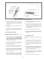
4. Connect the power cable, gas hose, and switch
cord to the wire feeder (see Fig. 2.1)
5. Remove retaining pin on wire feeder connector;
insert torch inlet fitting fully; and then reinsert re-
taining pin to lock fitting in place. Be sure retaining
pin is completely pushed in before feeding the wire.
6. Use the inching switch on the wire feeder to inch
the wire through the torch.
7. The torch is now ready to operate. Refer to your
wire feeder instruction booklet for operating de-
tails.

10
1 Short contact tips are generally recommended to give proper wire stick out for flux cored wire welding.
2 Medium contact tips are generally recommended to give proper wire stick out for spray transfer Mig welding.
3 Long contact tips are generally recommended to give good visibility and proper wire stick out for dip transferring welding.
* The use of Heavy Duty tips & tubes and Extra Heavy Duty threaded nozzles extends the rating of the MT-400 to 500 amps @ 60% duty cycle
in CO
2
.
+ Use with Nozzle Adaptor (999452)
² Use with Nozzle Adaptor (948793) and Extra Heavy Duty Adaptor (17318)
u New ID for improved arc performance on steel/flux cored wire.
Notched for improved arc starting and increased tip life.
Table 1.4.1 Recommended Contact Tips, Tubes and Adaptors
Standard Duty Heavy Duty* Heavy Duty*
Wire Contact Tips Contact Tips Contact Tubes
Sizes & Type Short
1
Medium
2
Long
3
Short
1
Medium
2
Short
1
Medium
2
For Hard and Cored Wires
.023 (.6mm) - 20543 999742 - - - -
.030 (.8mm) - 20544 996994 - - - -
.035 (.9mm) - 996995 996996 - - - 17163
.040 (1.0mm) - 37287 37288 - - - -
.045 (1.2mm) 999578u 37290u 996998u - 37286u - 37292u
.052 (1.4mm) 948340u 2075349u - - 17778u - 17155u
1/16 (1.6mm) 948341u 37289u - - 37291u - 17157u
5/64 (2.0mm) - 2075230u - 948832u - 17159u -
3/32 (2.4mm) - - - 948833u - 17161u -
For Soft (Aluminum) Wires
.023 (.6mm) - 20543 999742 - - - -
.030 (.8mm) - 20544 996994 - - - -
.030 (.8mm) - 36884 --- - -
.035 (.9mm) - 996995 996996 - - - -
.035 (.9mm) - 36885 --- - -
.040 (1.0mm) - 37287 37288 - - - -
3/64 (1.2mm) - 996999 - - 17765 17164
3/64 (1.2mm) - 36886 --- - -
1/16 (1.6mm) - 996997 - - 948835 - -
Tip Adaptor for 17983 (all diameters)+ 17984 (all diameters)+ Not Available
Slide-On Nozzles
Tip Adaptor for 948785 (all diameters)² 17766 (.045"-1/16")² Collet Body 17136
Threaded Nozzles 948786 (5/64"-3/32")² Collet 17135²
TABLE 1.4.2 Recommended Nozzles Accessories
Nozzle Slide-On, Self-Insulated* Threaded+
Standard Duty Heavy Duty Extra Heavy Extra Heavy
Description I.D. Standard Long-Lifeu Standard Long-Lifeu duty (Brass) Duty
#6 Tapered 3/8 998895 998895XL - - - -
#8 1/2 998893 998893XL 999471 999471XL - 948767
#10 5/8 998894 998894XL 999472 999472XL - 948768
#12 3/4 - - 999473 - 17350 948769
#12 Spot 3/4 17316§ - 999625 - - -
#16 Spot 1 - - - - - 999900
* Slide-on, Self-Insulated Nozzles require Adaptor 999452.
+ Threaded Nozzles require Extra Heavy Duty Adaptor 17318 and Nozzle Adaptor 948793.
§ Requires 17293 Tip Adaptor (replaces standard tip adaptor) and 17321 Nozzle Insulator.
u Long-life nozzles are coated to reduce weld spatter adherence and extend life on nozzle.

11
III. OPERATION
3.1 OPERATING SAFETY PRECAUTIONS
Comply with all ventilation, fire and other safety require-
ments for arc welding as established in the SAFETY
Section at the front of this manual.
Comply, also, with the following precautions:
a. Whenever welding above 250 amps, a No. 14 fil-
ter lens should be worn on your protective helmet.
Up to 250 amps, No. 11 or 12 filter lens is recom-
mended.
b. The radiant energy of the arc can decompose chlo-
rinated solvent vapors, such as trichloroethylene
1. Install the proper feed roll (see Table 1.3) to the
wire feeder. Refer to the wire feeder booklet for
installation and adjustment details.
2. Connect the proper wire outlet guide (see Table
1.3) to the wire feeder connector assembly as
shown in figure 1.3.
3. Secure the outlet guide into the front clamp of the
accessory support assembly on the wire feeder
(refer to wire feeder instruction booklet).
4. Connect the power cable, gas hose, and switch
cord to the wire feeder (see Fig. 2.1)
5. Remove retaining pin on wire feeder connector;
insert torch inlet fitting fully; and then reinsert re-
taining pin to lock fitting in place. Be sure retaining
pin is completely pushed in before feeding the wire.
6. Use the inching switch on the wire feeder to inch
the wire through the torch.
7. The torch is now ready to operate. Refer to your
wire feeder instruction booklet for operating de-
tails.
The MT-200 or MT-400 torch is supplied with liner
and contact tip for a particular wire size and No. 8,
10 or 12 standard-duty nozzle installed. If desiring
to change these components for another wire size
as given in Table 1.4.1 through 1.4.3, refer to the
Maintenance Section for instructions.
The MT-200 is rated to operate up to 300 amps
using CO
2
; 200 amps using mixed gases (60% duty
cycle).
The MT-400 is rated to operate up to 400 amps us-
ing CO
2
; 250 amps using mixed gases (60% duty
cycle).
Wire Liner
Size & Type 10' 12' 15' 25'
Hard Wires & Cored Wires
.023" (.6mm) 999743* 34929* - -
.030" (.8mm) 948850 17717 - -
.035" (.9mm) 2075237 17718 2075238 18235
.045" (1.2mm) 2075237 17718 2075238 18235
.052" (1.4mm) 2075239 17719 2075240 18236
1/16" (1.6mm) 2075239 17719 2085240 18236
5/64" (2.0mm) 2075245 17720 2075246 -
3/32" (2.4mm) 2075245+ 17720 2075246 -
Soft Wires (aluminum)
.035" (.9mm) 948862 33931 - -
3/64" (1.2mm) 948863 34932 - -
1/16" (1.6mm) 19065** - - -
TABLE 1.4.3 Recommended Liners Accessories
* Requires support liner for .023" wire. Order P/N 999797 for 10 ft. or P/N 34930 for 12 ft.
** Requires Support Liner, P/N 34930.
+ 45° curved wire guide (P/N 18243) recommended for 3/32" wire.
Figure 2.1 - MT-200 or MT-400 Torch and Wire Feed Connector Shown
Attached to MIG-35 Wire Feeder
RETAINING
PIN
WIRE FEEDER
CONNECTOR
MT-200 OR MT-400
TORCH
SWITCH
CORD
(24" lg.)
GAS HOSE
(24" lg.)
POWER CABLE (24" lg.)
(Part of Wire Feeder
Connector Assembly)

12
and perchloroethylene, to form phosgene, even
when these vapors are present in low concentra-
tions. Do NOT weld where chlorinated solvents
are present in atmospheres in or around the arc.
c. Do NOT touch the electrode, contact tip or metal
parts in contact with them when power is ON; all
are electrically energized (HOT) and can cause a
possibly fatal shock. DO NOT allow electrode to
touch grounded metal; it will create an arc flash
that can injure eyes. It may also start a fire or
cause other damage.
d. When working in a confined space, be sure it is
safe to enter. The confined space should be tested
for adequate oxygen (at least 19%) with an ap-
proved oxygen measuring instrument. The con-
fined space should not contain toxic concentrations
of fumes or gases. If this cannot be determined,
the operator should wear an approved air supplied
breathing apparatus.
Avoid gas leaks in a confined space, as the leaked
gas can dangerously reduce oxygen concentra-
tion in the breathing air.
DO NOT bring gas cylinders to confined spaces.
When leaving a confined space, shut OFF gas
supply at the source to prevent gas from leaking
into the space. Check the breathing atmosphere
in the confined space to be sure it is safe to reen-
ter.
e. Never operate the equipment at currents greater
than the rated ampere capacity; over-heating will
occur.
f. Never operate equipment in damp, wet or confined
areas without suitable insulation for protection
against shock. Keep hands, feet and clothing dry
at all times.
g. Whenever the equipment is left unattended, turn
all control and power source switches and gas sup-
plies OFF and open the main line switch.
h. Wear dark substantial clothing to protect exposed
skin from arc burn, sparks and flying hot metal.
i. Turn off welding power before adjusting or replac-
ing electrodes, contact tips, nozzles, or contact tip
adaptors.
3.2 PRE-WELD REQUIREMENTS
Before welding, refer to feeder manual for pre-weld re-
quirements and checklist. Also check that:
a. Correct size liner, guide tube, contact tip and nozzle
are installed and uncontaminated by dirt or spat-
ter.
b. Wire is properly threaded through gun.
c. Nozzle is free from excessive spatter.
If all pre-weld requirements have been met for feeder
and torch, turn on all required power controls and pro-
ceed to weld.
IMPORTANT
For argon shield gas applications, copper nozzles
should be used in place of brass nozzles.
When the POWER is ON, and torch trigger is de-
pressed, the electrode wire becomes electrically
HOT. Do NOT touch the wire as it may cause a
possibly fatal shock. Do NOT allow wire to touch
grounded metal surfaces other than the work to
be welded.
3.3 WELDING PROCEDURE
a. On each new application, weld trial pieces of simi-
lar metal to determine any necessary welding ad-
justments.
b. When the trigger is squeezed, weld wire feeds con-
tinuously into the arc and the resulting weld puddle
is protected by the shielding gas. Protect the arc
from strong drafts which can disrupt shielding gas
coverage and cause porous welds.
NOTE
Correct torch position, and coating of an anti-spat-
ter compound on all torch surfaces exposed to
spatter, reduces spatter accumulation.
IMPORTANT
Keep hoses, and cables from touching hot metal.
Do not lay torch down on hot metal.
c. To stop the arc, release the trigger.
NOTE
Release the trigger, pull torch away from work only
far enough to prevent welding wire from freezing
in weld puddle. Gas will continue to flow for a short
period.
d. When putting torch down, comply with (Step c) and
CAUTION in next paragraph.

13
servicing be done by an authorized service facility.
Contact the Distributor from whom purchased for as-
sistance.
If so advised, the unit should be sent to the authorized
service facility, adequately packaged, in the original
shipping container, if possible, and shipped prepaid,
with a statement of the observed deficiency. Return
transportation charges are to be paid by Buyer. In all
cases other than when warranty is applicable, repairs
will be made at current list price for the replacement
part(s) plus a reasonable labor charge.
4.2 INSPECT AND SERVICE TORCH REGULARLY
a. Clean accumulated dirt from all areas, particularly
electrical parts where metallic particles can cause
short circuits. Blow out liner with compressed air
when changing wire. Compressed air should NOT
exceed 30 psig (2.1 bar).
b. Tighten loose hardware including all gas and elec-
trical connections. (Loose power connections over-
heat during welding).
c. Regularly inspect insulation on equipment for pos-
sible damage or wear. Check for frayed and
cracked insulation. Before using equipment again,
make necessary repairs or replace all worn or dam-
aged insulation, hoses, cables, conduit, and con-
nectors.
With any repairs, make sure that metallic parts do
not protrude from insulation. Damaged insulation
can expose the conductor. If it should touch
grounded metal, it would create an arc flash. If it
should touch the body, it could cause a fatal shock.
d. Periodically remove any weld spatter or foreign
matter which has accumulated around the nozzle
orifice and contact tip. To ease spatter removal,
spray a thin film of anti-spatter compound on con-
tact tip and nozzle before welding and reapply the
compound after cleaning of tip and nozzle.
e. Replace contact tip if worn.
f. Remove any accumulation around trigger that may
make it stick, or cause short circuits.
To avoid shock, do not depress trigger while han-
dling contact tip or nozzle parts or while disassem-
bling torch.
IMPORTANT
Never use torch as a hammer to remove spatter.
3.4 SHUTDOWN PROCEDURE
When welding is completed, shut down the equipment
as follows:
a. Shut OFF all power controls.
b. Turn off gas at source.
c. Place torch in safe location.
Do not allow protruding welding wire to touch a
grounded metal surface.
d. Coil or drape hose and cable without sharp bends.
IV. SERVICE
4.1 SERVICE PROCEDURE
Always shut OFF all power and gas supplies be-
fore attempting inspection, maintenance, or repair
unless otherwise instructed here. Remove main
line fuses or lock and red tag switches.
If power source is ON, electrode wire becomes elec-
trically HOT when gun trigger is pressed, and drive
rolls start. Keep fingers clear of drive rolls. Do
NOT touch wire or metal parts contacting it or al-
low wire to touch grounded metal. It may cause
possibly fatal shock, fire or other damage. (See
Operating Safety Precautions in preceding section,
item 3.1).
Equipment which is not functioning properly should not
be used until all required repairs have been completed
and the equipment has been tested to ascertain that it
is in proper operating condition.
Inspection, troubleshooting, and repair of this equip-
ment as indicated in this manual may ordinarily be un-
dertaken by a competent person having at least gen-
eral experience in the maintenance and repair of equip-
ment of this nature.
No such maintenance or repair should ever be un-
dertaken by anyone not having such qualifications.
It is recommended that worn parts be replaced with
parts manufactured and sold by ESAB Welding & Cut-
ting Products.
Except for inspection, troubleshooting, and repairs in-
dicated in this manual, it is recommended that all other

14
4.3 NOZZLES
IMPORTANT
Do not hammer torch or nozzle to remove spatter.
Spatter can be removed from the inside of the nozzle
with a hand reamer or file. Adherence of spatter can
be minimized and removal made easier by coating the
inside of the nozzle with No. 65 Nozzle Anti-Spatter
Compound.
4.4 WIRE FEED LINER (Except 0.023-in liner, see
Section 4.4)
To remove liner for cleaning or replacement, proceed
as follows:
1. Remove nozzle, contact tip, tip adaptor and front
insulator.
2. Loosen the setscrews in the curved wire guide
(through hole of front insulator, 999474) and the
cable inlet fitting (see Fig. 4) with a 5/64-in. hex-
key.
3. Lay the torch cable out relatively straight. Rotate
the cable inlet fitting counterclockwise a few turns
which should force the liner to slip out of the fitting
slightly. You should then be able to grab the end of
the liner by hand and pull it out of the torch keep-
ing the cable relatively straight while pulling.
at a time. An occasional slight whip-snapping of
the inlet flex support will also facilitate liner instal-
lation is illustrated below.
SETSCREW
5-6 MM
(3/16" - 1/4")
4. Be sure to wear proper eye and face protection.
Blow out metallic chips, grit, etc. from the liner
and the handle and cable assembly with com-
pressed air.
NOTE: Direct the initial blast of air away from the
parts to clear moisture that occasionally
accumulates in compressed air lines.
5. Inspect the small gas sealing O-ring on the inlet
ferrule. Replace it if damaged. Make sure the O-
ring is properly located in the groove.
6. Remove all burrs from the O.D. of the liner's bare
spring end (particularly if installing a new liner) to
prevent snagging while pushing the liner through
the cable.
7. With the torch cable laying straight, insert the bare
end of the liner into the cable inlet fitting. Then
push the liner slowly through the cable. To pre-
vent possible kinking of the liner, it is recom-
mended to push it in no more than 150 mm (6-in.)
8. After seating the liner ferrule fully into the cable
inlet fitting, lock the liner in place by tightening the
setscrew in inlet fitting. If setscrew is not tightened,
liner may shift in service causing gas to leak. Do
NOT overtighten.
9. If installing a used liner, it should extend beyond
the end of the curved wire guide 3/8 to 7/16-in (9
to 11mm). If short rotate the torch handle in the
counter clockwise direction as illustrated below
(white arrow) to force the liner to extend more. If
liner is extending excessively, then rotate the
handle in the clockwise direction (dark arrow).
10. If installing a new replacement liner, it should be
extending several inches past the curved wire
guide. Proceed as follows:
a. Snip off excess liner with a sharp cutting tool
so that the liner extends 3/16-in. to 1/4-in. (5-
6mm) from the face of the nozzle adaptor.
b. Remove any sharp burrs on end (O.D. and I.D.)
of the spring liner. Burrs could cause wire to
bind during the feeding or the liner to sag dur-
ing reinstallation into the torch.

15
11. Install tip adaptor wrench tight to seat the liner.
Then tighten the setscrew in the curved wire guide
with the supplied 5/64-in. (2mm) hex key. Do NOT
overtighten.
12. Install and tighten proper size contact tip with a
pair of pliers.
13. Install push-on nozzle. A slight rotating motion will
help slide the nozzle past the friction rings and O-
ring.
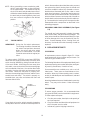
4.5 0.023-IN. WIRE FEED LINERS
To install liner and support liners into the torch, use the
following procedure (refer to Figure 4.4):
1. Remove nozzle, contact tip, tip adaptor (999452)
and front insulator (999474). Back out setscrew
in wire guide until it is flush with wire guide
O.D. (This setscrew must remain in wire guide to
prevent loss of shielding gas.)
2. Lay torch out straight and insert support liner
(999797) from inlet end of torch. Seat liner end
fitting firmly into torch inlet.
3. Snip off excess support liner protruding from wire
guide so that it is flush with end of wire guide.
4. Remove the support liner and cut off an additional
1/2-in. (13mm). Deburr and reinstall in torch.
Tighten setscrew in torch inlet fitting. Do not tighten
setscrew in wire guide.
5. With torch laying straight, insert inner liner (999743)
from torch wire guide end. Push liner in all the
way until the small brass liner fitting seats firmly
against the end of the wire guide. Reinstall front
insulator and tip adaptor.
6. Excess liner should be extending from torch inlet
end. Tighten setscrew in the support liner fitting to
lock inner liner in place. Leaving 3/8-in. of inner
liner extending from support liner fitting, snip off
excess and deburr.
7. Install contact tip and tighten with a pair of pliers.
8. Install nozzle. A slight rotating motion may be re-
quired for sliding the nozzle past the friction rings
and O-ring.
4.6 CURVED WIRE GUIDE
To replace the curved wire guide (21064) proceed as
follows:
1. Remove the nozzle, contact tip, tip adaptor, nozzle
adaptor, front insulator, liner and shoulder ring.
2. Remove the switch housing (998858) (refer to Sec-
tion 4.6) which will expose a hex-section on the
torch body.
3. Remove the handle end cap and wire guide insu-
lator unless the insulator is being replaced. The
insulator should be replaced if torch has been in
service for an extended period.
4. Place the wire guide in a vise. Using an adjust-
able wrench, turn the torch body counterclockwise
to unscrew the wire guide.
5. Reassemble components in reverse order.
Figure 4.4 - Installing 0.023-in. Inner and Support Liners

16
MOLDED
RUBBER KEYS
NOTE: When assembling a new curved wire guide,
do NOT apply teflon tape or other lubricants
on the pipe threads. The threads should be
dry since the torch body threads have a film of
conductive material already applied. Assemble
the torch body to the wire guide by hand, and
then use a wrench to tighten to the desired
position.
4.7 TORCH SWITCH
IMPORTANT: During the first switch replacement.
The housing should be removed and
the switch lead positions observed.
When the switch and other switch
parts are reassembled, the leads
should be returned to the original po-
sition.
To replace switch (2075220), press lever (2075214)
down and then remove metal clamp (2075219) from
switch housing (998858) by sliding it towards the rear
of the torch handle. After lifting the lever away from
the handle, remove the switch from the mounting lugs
on the underside of the lever. You can then disconnect
the leads from the old switch and reconnect to the
new switch. Make sure the switch is properly posi-
tioned on the mounting lugs of the lever and then reas-
semble lever and clamp. The switch is properly as-
sembled when you press and release the lever and
hear two distinct clicks.
switch, disassemble as described above but you must
also remove the plastic housing from the handle and
cut off the molded-in rubber keys (located on the un-
derside where illustrated) with a wire cutter or some
other sharp instrument. Spread the housing apart so
that it can slide upward off the handle. Disconnect the
switch and then reconnect on the top side of handle so
that the leads can be tucked neatly into the handle cav-
ity. Reassemble the housing from the opposite side.
Reassemble switch components as described in the
preceding paragraph.
4.8 HANDLE AND CABLE ASSEMBLY (See Figure
5.1)
The handle and cable assembly includes the power
cable switch leads, and gas and wire passages. The
outer jacket should be examined periodically for signs
of minor damage which may be repaired by the cus-
tomer. If severe damage occurs, causing torch mal-
functions, the handle and cable assembly should be
replaced.
V. REPLACEMENT PARTS
5.1 GENERAL
All replacement parts are keyed in figure 5.1. Other
replacement parts by part number and part name. Do
not order by part number alone.
The following illustrations of the equipment identify each
replacement part by part number, description and quan-
tity used (in parentheses, if more than one).
Some assemblies are available as a unit or as indi-
vidual parts. These parts are listed below such as-
semblies. When any of the assembly parts is a subas-
sembly, its individual parts are listed below it, indented
another space.
Attaching hardware items are listed below the part they
attach. They may not be shown. Order them sepa-
rately.
5.2 ORDERING
To assure proper operation, it is recommended that
only genuine ESAB parts be used with this equipment.
To order replacement parts:
a. Give the part number, description and quantity of
each part required.
b. Give part number and description of equipment on
which the parts are to be used.
c. Indicate any special shipping instructions.
If you desire to have the switch assembly located on
the top side of the torch handle for thumb operation of

17
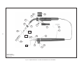
Fig. 5.1 - Replacement Parts - MT-200 & MT-400 Basic Torch Assemblies
** Denotes Items
Not Included With
Basic Torch
1
8
2
20
21A **
21B **
22 **
23 **
16
15
17
5
18
14
13 12
3
19
6
4
9
7
24 **

18
Replacement Parts List for Figure 5.1.
ITEM QTY. PART
NO. REQ'D. NO. DESCRIPTION
1 1 Handle and Cable Assembly:
998890 10-Ft., MT-200 (includes Handle 20829 and Cable 21097)
17715 12-Ft., MT-200 (includes Handle 20829 and Cable 21098)
998889 15-Ft., MT-200 (includes Handle 20829 and Cable 21099)
948075 10-Ft., MT-400 (includes Handle 20948 and Cable 21146)
17716 12-Ft., MT-400 (includes Handle 20948 and Cable 21147)
948076 15-Ft., MT-400 (includes Handle 20948 and Cable 21148)
18233 25-Ft., MT-400 (includes Handle 20948 and Cable 21149)
2 2 2062294* Terminal, (Supplied in Pkg. of 10)
3 2 950400* Clamp (Supplied in Pkg of 10)
4 1 948069* Plug Housing
5 2 2062344* Plug Terminal (Supplied in Pkg of 10)
6 2 493552* O-Ring .489ID x .070 Neopr 70A
7 1 * Setscrew #8-32 x 1/8"
8 1 * Hex Key 5/64" (Supplied - not shown)
9 1 20883* Adaptor, Inlet
12 1 998858 Switch Housing, MT-200
1 2075745 Switch Housing, MT-400
13 1 20885* End Cap, MT-200
1 2075215* End Cap, MT-400
14 1 998892 Wire Guide Insulator, MT-200
1 999475 Wire Guide Insulator, MT-400
15 1 185W31 Shoulder Ring
16 1 998859 Curved Wire Guide, MT-200 (Includes #8-32 x 3/16"
999453 Setscrew & a 5/64" Hex Key)
1 18234 Curved Wire Guide, MT-400 (Includes #8-32 x 3/16"
Setscrew & a 5/64" Hex Key)
17 1 2075220 Switch
18 1 999474 Front Insulator
19 1 2075214 Lever
20 1 2075219 Clamp
21A** 1 999452 Nozzle Adaptor (Includes O-Ring & 2-Friction Ring)
21B** 1 17983 Tip Adaptor
22** 1 - Contact Tip (See Figure 1.4 & Table 1.4.1)
23** 1 - Nozzle (See Figure 1.4 & Table 1.4.2)
24** 1 - Liner (See Table 1.4.3) includes:
O-Ring - 2064068 (Supplied in Pkg of 10)
* Item included with each Handle & Cable Assembly.
** Denotes Items not included with Basic Torch.
MT-200 Basic Torch Assembly, 10-Ft., 998888 MT-400 Basic Torch Assembly, 10-Ft., 999469
MT-200 Basic Torch Assembly, 12-Ft., 948921 MT-400 Basic Torch Assembly, 12-Ft., 948922
MT-200 Basic Torch Assembly, 15-Ft., 998887 MT-400 Basic Torch Assembly, 15-Ft., 999470
MT-400 Basic Torch Assembly, 25-Ft., 18232

19
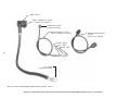
Figure 5.2 - Replacement Parts - Wire Feeder Connector Assembly (for Mig-35/Digimig Wire Feeders) -- P/N 2075378
u PIN - 2075221
u W. F. CONNECTOR - 2075380
(includes: LUG - 182W87)
CONNECTOR - 2075366
(included with 2075381)
u GAS HOSE ASS'Y - 2075381
(includes: CONNECTOR - 2075366)
(2) CLAMP - 98W43
NUT - 136Z08
NIPPLE - 11N22
LUG - 182W87
(Included with 2075380)
u SWITCHLEAD/PLUG ASS'Y
- 2075216
(includes PLUG - 2062336)
u Items included with WIRE FEEDER CONNECTOR ASS'Y (ESAB) - 2075378

ESAB Welding & Cutting Products
PO Box 100545 Florence SC 29501-0545
F-12-778H 06/99 Printed in U.S.A.
IF YOU DO NOT KNOW WHOM TO CALL
Telephone: (800) ESAB-123/ Fax: (843) 664-4452/ Web:http://www.esab.com
Hours: 7:30 AM to 5:00 PM EST
A. CUSTOMER SERVICE QUESTIONS:
Order Entry Product Availability Pricing Delivery
Order Changes Saleable Goods Returns Shipping Information
Eastern Distribution Center
Telephone: (800)362-7080 / Fax: (800) 634-7548
Central Distribution Center
Telephone: (800)783-5360 / Fax: (800) 783-5362
Western Distribution Center
Telephone: (800) 235-4012/ Fax: (888) 586-4670
B. ENGINEERING SERVICE: Telephone: (843) 664-4416 / Fax : (800) 446-5693
Welding Equipment Troubleshooting Hours: 7:30 AM to 5:00 PM EST
Warranty Returns Authorized Repair Stations
C. TECHNICAL SERVICE: Telephone: (800) ESAB-123/ Fax: (843) 664-4452
Part Numbers Technical Applications Hours: 8:00 AM to 5:00 PM EST
Performance Features Technical Specifications Equipment Recommendations
D. LITERATURE REQUESTS: Telephone: (843) 664-5562 / Fax: (843) 664-5548
Hours: 7:30 AM to 4:00 PM EST
E. WELDING EQUIPMENT REPAIRS: Telephone: (843) 664-4487 / Fax: (843) 664-5557
Repair Estimates Repair Status Hours: 7:30 AM to 3:30 PM EST
F. WELDING EQUIPMENT TRAINING:
Telephone: (843)664-4428 / Fax: (843) 679-5864
Training School Information and Registrations Hours: 7:30 AM to 4:00 PM EST
G. WELDING PROCESS ASSISTANCE:
Telephone: (800) ESAB-123 / Fax: (843) 664-4454 Hours: 7:30 AM to 4:00 PM EST
H. TECHNICAL ASST. CONSUMABLES:
Telephone : (800) 933-7070 Hours: 7:30 AM to 5:00 PM EST
ESAB Welding & Cutting Products, Florence, SC Welding Equipment
COMMUNICATION GUIDE - CUSTOMER SERVICES
-
 1
1
-
 2
2
-
 3
3
-
 4
4
-
 5
5
-
 6
6
-
 7
7
-
 8
8
-
 9
9
-
 10
10
-
 11
11
-
 12
12
-
 13
13
-
 14
14
-
 15
15
-
 16
16
-
 17
17
-
 18
18
-
 19
19
-
 20
20


ESAB MT-400 & MT-400EHD* Mig Welding Gun Troubleshooting instruction
- Catégorie
- Système de soudage
- Taper
- Troubleshooting instruction
- Ce manuel convient également à
dans d''autres langues
Documents connexes
-
ESAB 452CVCC & 582CVCC DC Welding Power Sources Manuel utilisateur
-
-
-
-
-
-
-
-
-