Smithco SweepStar 48H and 60 Mode d'emploi
- Taper
- Mode d'emploi

August 2015
Gas and Diesel SweepStar 60
Model 76-000-D and 77-100-C
High Lift SweepStar 48
Model 48-500-A
Product Support: Hwy SS & Poplar Ave; Cameron WI 54822
1-800-891-9435 productsupport@smithco.com
Operator’s

Englsih
Spanish
French
CONTENTS
Introduction..........................................................................1-11
Introduction..............................................................................1
Symbols................................................................................2-3
Safety ...................................................................................4-5
Safe Practices.........................................................................6
Specifications .......................................................................7-8
Setup .......................................................................................9
Controls & Instruments.................................................... 10-13
Service............................................................................... 14-16
Operation......................................................................... 14-15
Battery ...................................................................................16
Introducción...................................................................... S2-15
Introducción............................................................................ S3
Símbolos............................................................................. S4-5
Seguridad e Cauciones de Seguridad...................................6-7
Procedimientos seguros........................................................ S8
Especificaciones...............................................................S9-10
Puesta en marcha................................................................. S11
Controles e instrumentos ................................................S12-15
Servicio............................................................................S16-18
Operación ........................................................................S16-17
Batería .................................................................................. S18
Introduction......................................................................... F3-1
Introduction..............................................................................F3
Symboles ............................................................................ F4-5
Sécurité & Précautions........................................................ F6-7
Méthodes pratiques de sécurité..............................................F8
Caractéristiques ................................................................ F9-10
Préparation ............................................................................F11
Commandes & Instruments ............................................ F12-15
Service courant .............................................................. F16-18
Fonctionnement .............................................................. F16-17
Batterie................................................................................. F18
Autres.................................................................................... F19
Declaration of Conformity - Déclaration de conformité ..............
Warranty- Garantia -Garantie ......................................................
OtrosOtros
OtrosOtros
Otros

1
English
PARTS MANUALS AVAILABLE ONLINE AT smithco.com
INTRODUCTION
Thank you for purchasing a
SmithcoSmithco
SmithcoSmithco
Smithco
product.
Read this manual and all other manuals pertaining to the Sweeper carefully as they contain safety, operating,
assembly and maintenance instructions. Failure to do so could result in personal injury or equipment damage.
Keep manuals in a safe place after operator and maintenance personnel have read them. Right and left sides are
from the operator’s seat, facing forward.
All
SmithcoSmithco
SmithcoSmithco
Smithco machines have a Serial Number and Model Number. Both numbers are needed when ordering
parts. Refer to engine manual for placement of engine serial number.
For product and accessory information, help finding a dealer, or to register your procuct please contact us at
www.Smithco.com.
Information needed when ordering replacement parts:
1. Model Number of machine
2. Serial Number of machine
3. Name and Part Number of part
4. Quantity of parts
For easy access record your Serial and Model numbers here.
lb/kg Empty
lb/kg Full
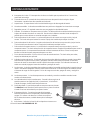
CALIFORNIA
Proposition 65 Warning
Engine exhaust and some of its constituents
are known to the State of California to
cause cancer, birth defects, and other
reproductive harm.
WARNING

2
Englsih
PARTS MANUALS AVAILABLE ONLINE AT smithco.com
SYMBOLS
Park Brake
Park Brake
Release
Hydraulic Oil
Level
Choke - OpenChoke - ClosedHand Throttle
Hour Meter Hour Meter Fuse
Glow PlugGlow Plug - OffGlow Plug - On
RPM Gasoline Diesel
Water
Temperature
Temperature
Light
Engine Oil
Engine - Stop Engine - Start Engine - Run
No Electrical
Power
Electrical Power
Read
Operator’s
Manual

3
English
PARTS MANUALS AVAILABLE ONLINE AT smithco.com
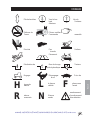
SYMBOLS
No Smoking Moving Parts
Manual
Operation
Pinch Point
Step Hot Surface
Hydraulic Fluid
Penetration
Lift Arm Tractor
Engage Disengage PTO
Ground Speed Fast Slow
H
High
L
Low
F
Forward
R
Reverse
N
Neutral
Warning
Danger
Caution
Up/RaiseDown/LowerUp/Down Arrow

4
Englsih
PARTS MANUALS AVAILABLE ONLINE AT smithco.com
SAFETY
SAFETY
Read and understand this manual and all safety signs before operating and maintaining. Review
the safety instructions and precautions annually.
TAKE NOTE! THIS SAFETY ALERT SYMBOL FOUND THROUGHOUT THIS MANUAL IS
USED TO CALL YOUR ATTENTION TO INSTRUCTIONS INVOLVING YOUR PERSONAL
SAFETY AND THE SAFETY OF OTHERS. FAILURE TO FOLLOW THESE INSTRUCTIONS
CAN RESULT IN INJURY OR DEATH.
THIS SYMBOL MEANS
ATTENTION!
BECOME ALERT!
YOUR SAFETY IS INVOLVED!
SAFETY SIGNAL WORDS
Note the use of the signal words DANGER, WARNING and CAUTION with the safety mes-
sages. The appropriate signal word for each has been selected using the following guide-
lines:
DANGER: Red. Indicates an imminently hazardous situation that, if not avoided, will result
in death or serious injury. This signal word is to be limited to the most extreme situations
typically for machine components which, for functional purposes, cannot be guarded.
WARNING: Orange. Indicates a potentially hazardous situation that, if not avoided, could
result in death or serious injury, and includes hazards that are exposed when guards are
removed. It may also be used to alert against unsafe practices.
CAUTION: Yellow. Indicates a potentially hazardous situation that, if not avoided, may
result in minor or moderate injury. It may also be used to alert against unsafe practices.

5
English
PARTS MANUALS AVAILABLE ONLINE AT smithco.com
SAFETY PRECAUTIONS
Connecting battery cables to the wrong post could result in personal injury and/or damage
to electrical system. Make sure battery and cables do not interfere or rub on any moving
part. Connect red positive (+) cable to battery first. When disconnecting remove black
negative (-) cable first.
Fuel is flammable. Caution must be used when storing or handling it. Do not fill fuel tank
while engine is running or in an enclosed area. Fumes are explosive and dangerous to
inhale. DO NOT SMOKE while filling fuel tank. DO NOT OVERFILL.
Before servicing or making adjustments to machine, stop engine and remove key from
ignition.
Follow all procedures and ONLY use parts prescribed by the manufacturer. Read the engine
manual before maintenance.
Battery Electrolyte is an acidic solution and should be handled with care. If electrolyte is
splashed on any part of your body, flush all contact areas immediately with liberal amounts
of water. Get medical attention immediately.
Use of booster battery and jumper cables. Particular care should be used when connecting a
booster battery. Use proper polarity in order to prevent sparks.Safety Precautions.
REMEMBER: If Safety Signs have been damaged, removed, become illegible or parts
replaced without decals, new decals must be applied. New decals are available from your
authorized distributor or factory.

6
Englsih
PARTS MANUALS AVAILABLE ONLINE AT smithco.com
SAFE PRACTICES
1. It is your responsibility to read this manual and all publications associated with this machine (engine, accesso-
ries and attachments).
2. Never allow anyone to operate or service the machine or its attachments without proper training and instructions.
Never allow minors to operate any equipment.
3. Learn the proper use of the machine, the location and purpose of all the controls and gauges before you operate
the equipment. Working with unfamiliar equipment can lead to accidents.
4. Wear all the necessary protective clothing and personal safety devises to protect your head, eyes, ears, hands
and feet. Operate the machine only in daylight or in good artificial light.
5. Inspect the area where the equipment will be used. Beware of overhead obstructions and underground obstacles.
Stay alert for hidden hazards.
6. Never operate equipment that is not in perfect working order or without decals, guards, shields, or other protective
devices in place.
7. Never disconnect or bypass any switch.
8. Carbon monoxide in the exhaust fumes can be fatal when inhaled, never operate a machine without proper
ventilation.
9. Fuel is highly flammable, handle with care. When filling tank stop 1 inch(2.54 cm) from top. Leave room for
expansion. DO NOT OVERFILL.
10. Keep engine clean. Allow the engine to cool before storing and always remove the ignition key.
11. After engine has started, machine must not move. If movement is evident, the neutral mechanism is not ad-
justed correctly. Shut engine off and readjust so the machine does not move when in neutral position.
13. Never use your hands to search for oil leaks. Hydraulic fluid under pressure can penetrate the skin and cause
serious injury.
14. This machine demands your attention. To prevent loss of control or tipping of the vehicle:
A. Use extra caution in backing up the vehicle. Ensure area is clear.
B. Do not operate on a slope greater than 10°. Pay careful attention to the inclinometer on you machine.
C. Do not stop or start suddenly on sloped surfaces.
D. Reduce speed on slopes and in all turns. Use caution when changing directions on all surfaces.
E. Do not change directions of travel on any slope.
F. Do not operate debris hopper lift or tailgate while on slopes.
G. Stay alert for holes in the terrain and other hidden hazards.
15. Before leaving operator’s position for any reason:
A. Disengage all drives.
B. Lower all attachments to the ground.
C. Set park brake.
D. Shut engine off and remove the ignition key.
16. Keep hands, feet and clothing away from moving parts. Wait for all movement to stop before you clean, adjust or
service the machine.
17. Keep the area of operation clear of all bystanders.
18. Never carry passengers.
19. Stop engine before making repairs/adjustments or checking/adding oil to the crankcase.
20. Use parts and materials supplied by SMITHCO only. Do not modify any function or part.
21. Do not remove the radiator cap when the engine is hot. When cooled, loosen cap slightly to the stop to relieve any
pressure before removing the cap completely.
These machines are intended for operation by well trained persons performing professional maintenance on golf
courses, sports turf, and any other area maintained turf and related trails, paths and lots. No guaranty as to the
suitability for any task is expressed or implied.

7
English
PARTS MANUALS AVAILABLE ONLINE AT smithco.com
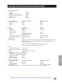
SPECIFICATIONS
FOR SWEEP STAR 60 GAS & DIESEL
WEIGHTS AND DIMENSIONS
Length 129" (328 cm)
Width 74.5" (179 cm)
Height with Hopper Down 82" (208 cm)
Height with Hopper Up 127" (323 cm)
Wheel Base 68.5" (174 cm)
Weight 2200 lbs (998 kg)
ROLL OVER PROTECTION BAR
Standard on all Machines
SOUND LEVEL GAS ENGINE DIESEL ENGINE
At ear level 92 dB 98 dB
At 3 ft (0.914 m) 86 dB 96 dB
At 30 ft (9.14 m) 64 dB 74 dB
ENGINE GAS DIESEL
Make Briggs & Stratton Kubota
Model# 543477 D 722 E3B
Type / Spec# 0175G1
Horsepower 31 Hp (23 kw) 18.8 Hp (14 kw)
Fuel Unleaded 87 Octane Gasoline Minimum
No. 2-D, S500: Low Sulfur Diesel (LSD) less than 500 ppm or 0.05 wt.%
No.2-D, S15: Ultra Low Sulfur Diesel (ULSD) less than 15 ppm or 0.0015 wt.%
Cooling System Air Cooled Liquid Cooled
Lubrication System Full Pressure Full Pressure
Alternator 20 Amp 40 Amp
Tire & Wheels Front: One 18 x 9.50 x 8 Multi-rib (20 psi; 1.4 bar)
Front tire and wheel fluid filled to 50 lbs. total. 28 pints of windshield washer
fluid or equivalent.
Rear: Two 24 x 13.00 x 12 Super Soft (18 psi; 1.3 bar)
Castor: 9 x 3.5 - 4 (20 psi; 1.4 bar)
SPEED
Forward Speed 0 to 12 m.p.h. (0-19 kph)
Reverse Speed 0 to 4 m.p.h. (0-6 kph)
BATTERY Automotive type 45 -12 volt
BCI Group Size 45
Cold Cranking Amps 480 minimum
Ground Terminal Polarity Negative (-)
Maximum Length 9" (23 cm)
Maximum Width 5.38" (14 cm)
Maximum Height 9" (23 cm)
FLUID CAPACITY
Crankcase Oil See Engine Manual See Engine Manual
Fuel 6 gallons (22,7 liters) 5 gallon (19 liters)
Hydraulic Fluid 5 gallon (19 liters) 5 gallon (19 liters)
Cooling 1 gallon (3.8 liters)
Grade of Hydraulic Fluid SAE 10W-40 API Service SJ or higher Motor Oil

8
Englsih
PARTS MANUALS AVAILABLE ONLINE AT smithco.com
SPECIFICATIONS FOR SWEEP STAR 48 HIGH LIFT
WEIGHTS AND DIMENSIONS HIGH LIFT
Length 121" (307 cm)
Width 60" (153 cm)
Height with Hopper Down 63" (160 cm)
Height with Hopper Up 126" (320 cm)
Wheel Base 70" (179 cm)
Weight 1900 lb (862 kg)
SOUND LEVEL
At ear level 90 dB
ENGINE
Make Briggs & Stratton
Model# 356447
Type / Spec# 0263G1
Horsepower 18 Hp (13kW)
Fuel Unleaded 87 Octane Gasoline Minimum
Cooling System Air Cooled
Lubrication System Full Pressure
Alternator 16 Amp
WHEELS & TIRE Front: One 18 x 9.50 x 8 Multi-rib (20 psi (1.4 bar))
Rear: Two 22 x 11.00 - 10 4-ply (20 psi (1.4 bar))
Castor: 9 x 3.50 - 4 (20 psi (1.4 bar))
SPEED
Forward Speed 0 to 10 m.p.h. (0-16 kph)
Reverse Speed 0 to 4 m.p.h. (0-6 kph)
BATTERY Automotive IBS type 45-12 volt
BCI Group Size 45
Cold Cranking Amps 480 minimum
Ground Terminal Polarity Negative (-)
Maximum Length 9" (23 cm)
Maximum Width 5.38" (14 cm)
Maximum Height 9" (23 cm)
FLUID CAPACITY
Crankcase Oil See Engine Manual
Fuel 6 gallon (22,7 liters)
Hydraulic Fluid 5 gallon (19 liters)
Grade of Hydraulic Fluid SAE 10W-40 API Service SJ or higher Motor Oil

9
English
PARTS MANUALS AVAILABLE ONLINE AT smithco.com
SETUP
The Sweep Star arrives from setup and ready for service.
1. Set park brake.
2. Check the tire pressure. Sweep Star 60: The front tire and castor wheels are 20 psi (1.4 bar) and the rear
tires are 18 psi (1.3 bar). Sweep Star 48: All tires and castor wheels are 20 psi (1.4 bar). All are maximum
pressures.
3. Check the installation of the battery, which is located
below the seat. This is a negative grounding system.
Connecting battery cables to the wrong post
could result in personal injury and/or damage to
the electrical system. Make sure battery and
cables do not interfere or rub on any moving
part. Connect the red positive(+) cable (A) to the
battery first. When disconnecting remove the
black negative(-) cable (B) first.
4. Check the engine oil and add as necessary. The dip stick
is located under the seat directly behind the control panel.
Oil fill is located on top of valve cover, use SAE 10W-40 API Service SJ or higher motor oil. DO NOT
OVERFILL.
5. Fill fuel tank, located on right side, with Unleaded 87 Octane gasoline (minimum) for gas machines and
No.1-D or No. 2-D, S500: Low Sulfur Diesel (LSD) less than 500 ppm or 0.05 wt.%; or No1-D or No.2-D,
S15: Ultra Low Sulfur Diesel (ULSD) less than 15 ppm or 0.0015 wt.%or diesel machines. When filling the
fuel tank stop when the fuel reaches 1 inch (2.54cm) from the top. This space is necessary for fuel
expansion. DO NOT OVERFILL.
Fuel is flammable. Caution must be used when storing or handling it. Do not fill fuel tank
while engine is running or in an enclosed area. Fumes are explosive and dangerous to
inhale. DO NOT SMOKE while filling the fuel tank. DO NOT OVERFILL.
6. Check hydraulic fluid level in tank. Remove cap and add SAE 10W-40 API Service SJ or higher motor oil
if necessary. Fluid level should be about 2"-2
1
/2" (5 - 6.4 cm) from the top of the tank when cold.
7. Machine should be greased before starting. See Maintenance part of manual.
8. Read operating instructions before starting.

10
Englsih
PARTS MANUALS AVAILABLE ONLINE AT smithco.com
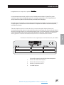
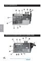
CONTROLS & INSTRUMENTS SWEEP STAR 60 GAS SWEEPER
CONTROLS & INSTRUMENTS SWEEP STAR 60 DIESEL SWEEPER

11
English
PARTS MANUALS AVAILABLE ONLINE AT smithco.com
CONTROLS & INSTRUMENTS
A. Circuit Breaker - The circuit breaker is a re-settleable fuse. To reset push down on it.
B. Hour Meter - The hour meter indicates hours of machine operation. It operates only when the ignition
switch is on.
C. Ammeter - The ammeter indicates the rate of charging or discharging of battery.
D. Ignition Switch - The ignition switch has three positions: Off - Run - Start.
E. Hand Throttle - The hand throttle is used to regulate engine speed.
F. Choke - The choke is used in starting the engine. Pull choke out to close choke plate when starting a
cold engine. Push in when engine starts. A warm engine may not require "choking" to start.
G. Reel Lift Lever - The reel lift lever is used raise and lower the reel. Pull back to raise the reel. Push
forward to lower the reel.
H. Hopper Lift Lever - The hopper lift lever is used to raise and lower the hopper. Pull back to raise the
hopper. Push forward to lower the hopper.
I. Tailgate Lever - The tailgate lever is used to open and close the tailgate. Pull back to open the tailgate.
Push forward to close the tailgate. Tailgate tends to creep open while sweeping. Frequently close the
tailgate to ensure no creeping.
J. Park Brake - The park brake is only a parking brake. Pull back to release, push forward to apply.
K. Oil Light - The oil light should come on when the ignition is on without the engine running and go out
when the engine is running. The oil light will light when the oil pressure is low. If oil light should come on,
shut engine off immediately and find the cause.
L. Charge Light - The charge light should come on when the ignition is on, without the engine running.
When the engine is running the light should go out. The charge light will light when the charging system
is not charging. If the charge light should come on, shut engine off and find cause.
M. Temperature Light - Temperature light will come on and a buzzer will sound when the engine starts to
overheat.
N. Glow Plug Indicator Light - When key is turned counter clockwise to "Preheat" the light will light. When it
goes out the engine is ready to start.
O. Stop Knob - The stop knob is used to start the engine. The knob must be pulled out to start and run the
engine. Push in to stop engine.
P. Electric Clutch - Controls the reel electrically. Move the switch to the left and the reel will disengage. If
moved to the right reel will engage. NOTE: Electric clutch must be disengaged before starting.
Q. Inclinometer - Indicates machine tilt on side hill. DO NOT EXCEED 10°.

12
Englsih
PARTS MANUALS AVAILABLE ONLINE AT smithco.com
CONTROLS & INSTRUMENTS SWEEP STAR 48 HSWEEPER

13
English
PARTS MANUALS AVAILABLE ONLINE AT smithco.com
CONTROLS & INSTRUMENTS
A. Hour Meter - The hour meter indicates hours of machine operation. It operates only when the ignition
switch is on.
B. Ignition Switch - The ignition switch has three positions: Off - Run - Start.
C. Hand Throttle - The hand throttle is used to regulate engine speed.
D. Reel Lift Lever - The reel lift lever is used raise and lower the reel. Pull back to raise the reel. Push forward
to lower the reel.
E. Hopper Lift Lever - The hopper lift lever is used to raise and lower the hopper. Pull back to raise the hopper.
Push forward to lower the hopper.
F. Tailgate Lever - The tailgate lever is used to open and close the tailgate. Pull back to open the tailgate.
Push forward to close the tailgate. Tailgate tends to creep open while sweeping. Frequently close the
tailgate to ensure no creeping.
G. Oil Light - The oil light should come on when the ignition is on without the engine running and go out when
the engine is running. The oil light will light when the oil pressure is low. If oil light should come on, shut
engine off immediately and find the cause.
H. Electric Clutch - Controls the reel electrically. Move the switch to the left and the reel will disengage. If
moved to the right reel will engage. NOTE: Electric clutch must be disengaged before starting.
I. Inclinometer - Indicates machine tilt on side hill. DO NOT EXCEED 10°.
J. Choke - The choke is used in starting the engine. Pull choke out to close choke plate when starting a
cold engine. Push in when engine starts. A warm engine may not require "choking" to start.

14
Englsih
PARTS MANUALS AVAILABLE ONLINE AT smithco.com
OPERATION
Before operating this machine, become familiar with all controls and functions of these units. Also complete all
maintenance requirements and read all safety warnings. By knowing the machine thoroughly, how it operates
and by doing the prescribed maintenance steps, you can expect relatively trouble-free operation for years to
come.
Beater reel MUST BE DISENGAGED before starting engine.
STARTING GAS ENGINE
1. Make sure the fuel flow valve, located on the fuel tank, is “ON.”
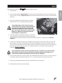
2. The ignition switch is located on control panel. Insert key (A) and turn
clockwise until engine starts (C). Release key and it will return to run
position (B). Use choke and hand throttle as necessary.
3. Allow engine to idle and warm up a few minutes before selecting a direc-
tion of travel.
STARTING DIESEL ENGINE
1. Make sure the fuel flow valve, located on the fuel tank, is “ON.” Also the
fuel valve, located on the fuel filter, is “ON.”
2. Pull the stop knob out, located on the control panel.
3. Place the speed control lever at more than half “Operation.”
4. Insert the key (A) into the key switch and turn it to “ON” (B). Check to see
if the oil pressure lamp and charge lamp are lit.
5. Turn the key counter clockwise to “preheat” (D) until the indicator lamp on
the control panel goes out.
6. Turn the key clockwise to “Start” (C). When engine starts, release the key
immediately. Do not hold the key in the “Start” position for more than 10
seconds.
7. Check to see that the oil pressure and charge lamps are off. If the lamps are still on, immediately stop the
engine (push the stop knob in) and determine the cause.
8. Warm up the engine at medium speed without load.
TAILGATE LEVER
Tailgate tends to creep open while sweeping. Frequently close the
tailgate to ensure no creeping.
SWEEP STAR 60 ACCELERATOR/REVERSE PEDAL
On the right floorboard of the Sweep Star 60 is a "rocker" pedal.
Push down on the front (G) with your foot and the machine will
accelerate. Push down on the rear of the pedal (H) with the heel of
your foot and the machine will go in reverse. The machine is in
neutral when foot is off the pedal.

15
English
PARTS MANUALS AVAILABLE ONLINE AT smithco.com
OPERATION
SWEEP STAR 48H ACCELERATOR/REVERSE PEDAL
On the right floorboard of the Sweep Star 48H is the accelerator
pedal (J) and the reverse pedal (K). The machine is in neutral when foot is
off the pedal.
DAILY CHECKLIST
1. Check park brake adjustment. Adjust as required.
2. Check engine oil level. Add as needed. DO NOT OVERFILL.
3. Tire pressure should be 20 psi (1.4 bar) on all Sweep Star 48 tires
and castor wheels. Tire pressure should be 20 psi (1.4 bar) on
Sweep Star 60 front tire and castor wheel, 18 psi (1.3 bar) on rear
tires.
4. Inspect electrical system for loose connections or frayed wiring,
including battery cables. Replace any faulty equipment or tighten if
loose.
5. Check hardware for loose or missing nuts, bolts, screws, etc., and tighten or replace as needed.
6. Inspect hydraulic lines for damage or leaks. Never use hands to inspect leaks.
7. Check hydraulic oil level in right side tank. The level should be 2" to 2
1
/
2
" (5-6.4 cm) from top of tank when
fluid is cold. If level is low, add SAE 10W-40 API Service SJ or higher motor oil.
8. Inspect steering, throttle and shift linkages for good hookups and clear travel.
9. Check controls for smooth, proper working operation. Lubricate as needed.
10. Check and clean all debris from engine compartment.
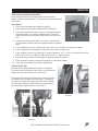
HOPPER LIFT SAFETY ARM
Each machine is equipped with two Hopper Lift Safety Bar.
They are stored on the Hopper Dump arms, on each side of the
hopper, with two bolts and wing nuts. See Picture 1.
The purpose of the Hopper Lift Safety Bar is to help the hopper
lift cylinders hold the hopper in the up position. The weight of
the hopper can cause the cylinders to retract. Bolt the Hopper
Lift safety bar around the cylinder shaft to prevent the hopper
from slowly lowering due to gravity. See Picture 2.
Picture 1
Picture 2

16
Englsih
PARTS MANUALS AVAILABLE ONLINE AT smithco.com
BATTERY
BATTERY
Batteries normally produce explosive gases which can cause personal injury. Do not allow flames, sparks or any
ignited object to come near the battery. When charging or working near battery, always shield your eyes and
always provide proper ventilation.
Battery cable should be disconnected before using “Fast Charge”.
Charge battery at 15 amps for 10 minutes or 7 amps for 30 minutes. Do not exceed the recommended charging
rate. If electrolyte starts boiling over, decrease charging.
Always remove grounded (-) battery clamp first and replace it last. Avoid hazards by:
1. Filling batteries in well-ventilated areas.
2. Wear eye protection and rubber gloves.
3. Avoid breathing fumes when electrolyte is added.
4. Avoid spilling or dripping electrolyte.
Battery Electrolyte is an acidic solution and should be handled with care. If electrolyte is
splashed on any part of your body, flush all contact areas immediately with liberal amounts
of water. Get medical attention immediately.
JUMP STARTING
Use of booster battery and jumper cables. Particular care should be used when connecting a
booster battery. Use proper polarity in order to prevent sparks.
To jump start (negative grounded battery):
1. Shield eyes.
2. Connect ends of one cable to positive (+)
terminals of each battery, first (A) then (B).
3. Connect one end of other cable to negative (-)
terminal of "good" battery (C).
4. Connect other end of cable (D) to engine block
on unit being started (NOT to negative (-)
terminal of battery)
To prevent damage to other electrical components on
unit being started, make certain that engine is at idle
speed before disconnecting jumper cables.
TOWING
When it is necessary to move the Sweep Star 48 without engine running, the bypass valve built into hydrostatic
pump must be “open” by turning it counterclockwise. An “open” valve allows fluid to pass through the wheels
freely. When normal, driven, operation is desired, valve should be closed by turning it clockwise. Failure to
“close” the valve with engine running means no power to wheels. Tow slowly. 2 m.p.h. or less.
The bypass valve is a
3
/8 diameter shaft with a
11
/64 hole for inserting something for leverage so you can turn it.
On the high lift it is on the top of the hydrostatic. On the ground level dump it is on the bottom of the hydro-
static.

S-1
Spanish
Manuales de piezas disponibles en línea en smithco.com
MANUAL DEL OPERADOR
Sweep Star 60 a gasolina y diesel
Modelos 76-000-D y 77-100-C
High Lift Sweep Star 48 (con elevador alto)
Modelos 48-500-A
Soporte de productos:
Hwy SS & Poplar Ave; Cameron WI 54822
1-800-891-9435 productsupport@smithco.com

S-2
Spanish
Manuales de piezas disponibles en línea en smithco.com
ÍNDICE
Introducción...................................................................... S2-15
Introducción.......................................................................... S3
Símbolos........................................................................... S4-5
Seguridad e Cauciones de Seguridad .................................6-7
Procedimientos seguros ...................................................... S8
Especificaciones .............................................................S9-10
Puesta en marcha............................................................... S11
Controles e instrumentos ..............................................S12-15
Servicio............................................................................S16-18
Operación......................................................................S16-17
Batería ................................................................................ S18
Otros ............................................................................................
Declaración de conformidad-........................Contratapa interior
Garantía.........................................................Contratapa interior
La page est en cours de chargement...
La page est en cours de chargement...
La page est en cours de chargement...
La page est en cours de chargement...
La page est en cours de chargement...
La page est en cours de chargement...
La page est en cours de chargement...
La page est en cours de chargement...
La page est en cours de chargement...
La page est en cours de chargement...
La page est en cours de chargement...
La page est en cours de chargement...
La page est en cours de chargement...
La page est en cours de chargement...
La page est en cours de chargement...
La page est en cours de chargement...
La page est en cours de chargement...
La page est en cours de chargement...
La page est en cours de chargement...
La page est en cours de chargement...
La page est en cours de chargement...
La page est en cours de chargement...
La page est en cours de chargement...
La page est en cours de chargement...
La page est en cours de chargement...
La page est en cours de chargement...
La page est en cours de chargement...
La page est en cours de chargement...
La page est en cours de chargement...
La page est en cours de chargement...
La page est en cours de chargement...
La page est en cours de chargement...
La page est en cours de chargement...
La page est en cours de chargement...
La page est en cours de chargement...
La page est en cours de chargement...
La page est en cours de chargement...
La page est en cours de chargement...
La page est en cours de chargement...
La page est en cours de chargement...
La page est en cours de chargement...
La page est en cours de chargement...
-
 1
1
-
 2
2
-
 3
3
-
 4
4
-
 5
5
-
 6
6
-
 7
7
-
 8
8
-
 9
9
-
 10
10
-
 11
11
-
 12
12
-
 13
13
-
 14
14
-
 15
15
-
 16
16
-
 17
17
-
 18
18
-
 19
19
-
 20
20
-
 21
21
-
 22
22
-
 23
23
-
 24
24
-
 25
25
-
 26
26
-
 27
27
-
 28
28
-
 29
29
-
 30
30
-
 31
31
-
 32
32
-
 33
33
-
 34
34
-
 35
35
-
 36
36
-
 37
37
-
 38
38
-
 39
39
-
 40
40
-
 41
41
-
 42
42
-
 43
43
-
 44
44
-
 45
45
-
 46
46
-
 47
47
-
 48
48
-
 49
49
-
 50
50
-
 51
51
-
 52
52
-
 53
53
-
 54
54
-
 55
55
-
 56
56
-
 57
57
-
 58
58
-
 59
59
-
 60
60
-
 61
61
-
 62
62


Smithco SweepStar 48H and 60 Mode d'emploi
- Taper
- Mode d'emploi
dans d''autres langues
Documents connexes
-
Smithco SweepStar 48H and 60 Mode d'emploi
-
-
-
-
-
-
-
-
