
Set-up Instructions
Rev May-2019 Part Number: Z97044_SI
WX310
WX320
WX330

Always Put Safety First!
Read these assembly instructions thoroughly before
beginning. Make sure each step is understood before
attempting it. Be familiar with all safety signs on the
machine and their meaning.
Tighten all fasteners to the torque value specied on
the last page. Recheck before using the machine.
WARNING!
Position the crate in a large open area to allow
access from all sides during assembly.
Stay clear of overhead power lines and obstructions
when lifting the machine during assembly. Contact
with power lines can cause electrocution. Contact
with obstructions can damage components or cause
them to fail.
Keep the assembly area clean to prevent slipping or
tripping.
Use a hoist when lifting components that weigh 50 lb
(23 kg) or more to avoid back injury.
All lifting devices (straps, slings, chains, ratchet
blocks) must comply with applicable local
regulations and certications. Wallenstein Equipment
Inc. cannot accept responsibility for the use of
sub-standard equipment and work practices.
Use lifting equipment with a capacity greater than the
weight of the component. Place jack stands or wood
blocking under the machine to securely stabilize it
before working on it during assembly.
Use the correct tool for the job. Repair or replace
broken or defective equipment or tools. Makeshift
tools can create safety hazards. A tool that breaks or
slips during use risks personal injury.
WARNING!
Avoid the risk of personal injury or machine damage!
Read the operator’s manual before using this
equipment. Carefully read all safety messages in the
manual and follow all safety signs on the machine.
IMPORTANT! Inspect for damage from shipping.
Immediately contact the shipping company if damage
is found.
Note: Some parts are attached to skid with screws.
Shipping brackets are not reused.
Assembly hardware is located inside operator's manual
tube.

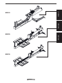
WX310
WX320
WX330
WX310WX320 WX330

1

2
WX310
B
A

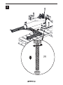
3
2X
B
A

4
WX310

1

WX320 WX330
2
A
B

3
4X
A
B

WX320 WX330
4

Pre-delivery Inspection
Inspect for damage from shipping. Immediately contact the
shipping company if damage is found.
Three-point Hitch Wood Splitter
Hydraulic Valve Control Function
Hydraulic Cylinder Function
All fasteners are Tight
Hydraulic Connections are tight
Safety Checks
All Safety Decals Installed
Guards and Shields Installed and Secured
Review Operating and Safety Instructions
5

Bolt Torque Specications
Checking Bolt Torque
The tables shown give correct torque values
for various bolts and capscrews. Tighten all
bolts to the torque values specied in the
table, unless indicated otherwise. Check
tightness of bolts periodically.
IMPORTANT! If replacing hardware, use
fasteners of the same grade.
IMPORTANT! Torque gures indicated in
the table are for non-greased or non-oiled
threads. Do not grease or oil threads
unless indicated otherwise. When using a
thread locker, increase torque values by
5%.
Note: Bolt grades are identied by their
head markings.
Imperial Bolt Torque Specications
Bolt
Diameter
Torque Value
SAE Gr. 2 SAE Gr. 5 SAE Gr. 8
lbf•ft N•m lbf•ft N•m lbf•ft N•m
1/4" 6 8 9 12 12 17
5/16" 10 13 19 25 27 36
3/8" 20 27 33 45 45 63
7/16" 30 41 53 72 75 100
1/2" 45 61 80 110 115 155
9/16" 60 95 115 155 165 220
5/8" 95 128 160 215 220 305
3/4" 165 225 290 390 400 540
7/8" 170 230 420 570 650 880
1" 225 345 630 850 970 1320
Metric Bolt Torque Specications
Bolt
Diameter
Torque Value
Gr. 8.8 Gr. 10.9
lbf•ft N•m lbf•ft N•m
M3 0.4 0.5 1.3 1.8
M4 2.2 3 3.3 4.5
M6 7 10 11 15
M8 18 25 26 35
M10 37 50 52 70
M12 66 90 92 125
M16 166 225 229 310
M20 321 435 450 610
M30 1,103 1 495 1,550 2 100
M36 1,917 2 600 2,700 3 675

Hydraulic Fitting Torque
1. Check are and are seat for defects
that might cause leakage.
2. Align tube with tting before tightening.
3. Hand-tighten swivel nut until snug.
4. To prevent twisting the tube, use two
wrenches. Place one wrench on the
connector body and tighten the swivel
nut with the second. Torque to values
shown.
If a torque wrench is not available, use the
FFFT (Flats From Finger Tight) method.
Wheel Lug Torque
It is an extremely important safety procedure
to apply and maintain proper wheel mounting
torque on your trailer axle. Torque wrenches
are the best method to assure the proper
amount of torque is being applied to a
fastener.
Wheel lugs should be torqued before rst
road use and after each wheel removal.
Check and re torque after the rst 10 miles
(16 km), 25 miles (40 km), and again
at 50 miles (80 km). Check periodically
thereafter.
WARNING!
Wheel lug nuts must be installed and
kept at the proper torque value to
prevent loose wheels, broken studs,
or possible separation of wheels from
axle.
• Start all lug nuts onto the threads by
hand.
• Tighten lug nuts in stages, following the
pattern shown in the Wheel Lug Nut
Torque table.
Hydraulic Fitting Torque
Tube Size
OD
Hex Size
Across
Flats
Torque value Flats From Finger
Tight
Inches Inches lbf•ft N•m Flats Turns
3/16 7/16 6 8 2 1/6
1/4 9/16 11–12 15–17 2 1/6
5/16 5/8 14–16 19–22 2 1/6
3/8 11/16 20–22 27–30 1-1/4 1/6
1/2 7/8 44–48 59–65 1 1/6
5/8 1 50–58 68–79 1 1/6
3/4 1-1/4 79–88 107–119 1 1/8
1 1-5/8 117–125 158–170 1 1/8
Values shown are for non-lubricated connections.
Wheel Lug Nut Torque
Wheel Size Units 1st Stage 2nd Stage 3rd Stage
8" lbf•ft
N•m
12–20
16–26
30–35
39–45.5
45–55
58.5–71.5
12" lbf•ft
N•m
20–25
26–32.5
35–40
45.5–52
50–60
65–78
13" lbf•ft
N•m
20–25
26–32.5
35–40
45.5–52
50–60
65–78
14" lbf•ft
N•m
20–25
26–32.5
50–60
65–78
90–120
117–156
15" lbf•ft
N•m
20–25
26–32.5
50–60
65–78
90–120
117–156
16" lbf•ft
N•m
20–25
26–32.5
50–60
65–78
90–120
117–156
4-Bolt
Wheel Lug Torque Pattern
5-Bolt 6-Bolt 8-Bolt

Couple appliqué sur les raccords
hydrauliques
Serrage des raccords coniques de
tube
1. Vériez l’évasement et le logement de
l’évasement pour repérer la présence éventuelle
de défauts qui peuvent causer une fuite.
2. Alignez le tube sur le raccord avant de serrer.
3. Serrez à fond l’écrou orientable jusqu’à ce qu’il
soit bien serré.
4. Pour éviter de tordre le tube, utilisez deux clés.
Placez une des clés sur le bâti du connecteur
et serrez l’écrou orientable avec la deuxième clé
selon le couple indiqué. Serrez au couple selon
les valeurs indiquées.
Si vous n’avez pas de clé dynamométrique, utilisez la
méthode FFFT (Plaques avec serrage manuel).
Couple appliqué sur les raccords hydrauliques
Diamètre
extérieur
du tube
Taille des
écrous
hexagonaux
à travers les
plaques
Couple de serrage Plaques avec
serrage manuel
Pouces Pouces lb•pi N•m Plaques Tours
3/16 7/16 6 8 2 1/6
1/4 9/16 11-12 15-17 2 1/6
5/16 5/8 14-16 19-22 2 1/6
3/8 11/16 20-22 27-30 1-1/4 1/6
1/2 7/8 44-48 59-65 1 1/6
5/8 1 50-58 68-79 1 1/6
3/4 1-1/4 79-88 107-119 1 1/8
1 1-5/8 117-125 158-170 1 1/8
Les valeurs indiquées s’appliquent aux raccords non lubriés.

Spéci cations relatives au couple de serrage des
boulons en unités impériales
Diamètre
du
boulon
Couple de serrage
SAE Gr. 2 SAE Gr. 5 SAE Gr. 8
lb•pi N•m lb•pi N•m lb•pi N•m
1/4 po 6 8 9 12 12 17
5/16 po 10 13 19 25 27 36
3/8 po 20 27 33 45 45 63
7/16 po 30 41 53 72 75 100
1/2 po 45 61 80 110 115 155
9/16 po 60 95 115 155 165 220
5/8 po 95 128 160 215 220 305
3/4 po 165 225 290 390 400 540
7/8 po 170 230 420 570 650 880
1 po 225 345 630 850 970 1 320
Spéci cations relatives au couple de serrage des
boulons en unités métriques
Diamètre
du boulon
Couple de serrage
Gr. 8,8 Gr. 10,9
lb•pi N•m lb•pi N•m
M3 0,4 0,5 1,3 1,8
M4 2,2 3 3,3 4,5
M6 7 10 11 15
M8 18 25 26 35
M10 37 50 52 70
M12 66 90 92 125
M16 166 225 229 310
M20 321 435 450 610
M30 1 103 1 495 1 550 2 100
M36 1 917 2 600 2 700 3 675
Couple appliqué sur les boulons
Vérication du couple appliqué sur les boulons
Les tableaux gurant ci-dessous donnent les valeurs
correctes de couple pour divers boulons et vis de
blocage. Serrez tous les boulons selon le couple
spécié dans le tableau, sauf mention contraire.
Vériez de temps à autre que les boulons sont bien
serrés.
IMPORTANT! Si vous remplacez de la
quincaillerie, utilisez des xations de la même
catégorie.
IMPORTANT! Les valeurs de couple de serrage
indiquées dans le tableau s’appliquent aux lets non
graissés et non huilés. Ne pas graisser ou huiler les
lets, sauf mention contraire. Lorsque vous utilisez
un enduit frein pour lets, augmentez la valeur de
couple de 5 %.
REMARQUE : Les catégories des boulons sont
indiquées sur leur tête.

Pre-delivery Inspection
Inspect for damage from shipping. Immediately contact the
shipping company if damage is found.
Three-point Hitch Wood Splitter
Hydraulic Valve Control Function
Hydraulic Cylinder Function
All fasteners are Tight
Hydraulic Connections are tight
Safety Checks
All Safety Decals Installed
Guards and Shields Installed and Secured
Review Operating and Safety Instructions
5

WX320 WX330
4

3
4X
A
B

WX320 WX330
2
A
B
La page est en cours de chargement...
La page est en cours de chargement...
La page est en cours de chargement...
La page est en cours de chargement...
La page est en cours de chargement...
La page est en cours de chargement...
La page est en cours de chargement...
La page est en cours de chargement...
-
 1
1
-
 2
2
-
 3
3
-
 4
4
-
 5
5
-
 6
6
-
 7
7
-
 8
8
-
 9
9
-
 10
10
-
 11
11
-
 12
12
-
 13
13
-
 14
14
-
 15
15
-
 16
16
-
 17
17
-
 18
18
-
 19
19
-
 20
20
-
 21
21
-
 22
22
-
 23
23
-
 24
24
-
 25
25
-
 26
26
-
 27
27
-
 28
28


Wallenstein WX320 Setup Instructions
- Taper
- Setup Instructions
dans d''autres langues
- English: Wallenstein WX320
Documents connexes
-
Wallenstein QC605B Assembly Instructions
-
-
-
-
-
-
-
-
-


