
Long
Short
4

Customer Service: 800-626-1126 | rev-a-shelf.com
2
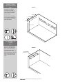
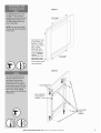
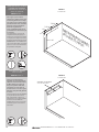
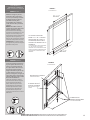
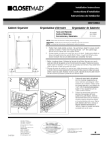
See Figure 1 for all drill
locations for the inside of
your cabinet. Use a pencil to
mark the 3 side wall holes
before drilling.
NOTE: If you are installing
into a frameless cabinet, you
must add 3/4” to the depth
dimensions shown.
Attach the Adjustable Side
Bracket to the cabinet wall
using 3 of the M4 x 18mm
wood screws (See Fig2).
Adjustable Bracket should sit
ush with the back of the face
frame or ¾” back from the
front of a frameless cabinet
wall.
FIGURE 1
FIGURE 2
ADJUSTABLE
BRACKET
STEP 1
CABINET WALL
SIDE DIMENSIONS
STEP 2
ATTACHING THE
FRAME
2/3
10-3/4”
7-9/16”
14-11/16”
7-9/16”
1/2”
Between
15-24”
2/3
10-3/4”
7-9/16”
14-11/16”
7-9/16”
1/2”
Between
15-24”
3
32
#2
BACK WALL OF CABINET

INSTALLATION INSTRUCTIONS: 5708 ABOVE THE APPLIANCE ORGANIZER 3
2/3
10-3/4”
7-9/16”
14-11/16”
7-9/16”
1/2”
Between
15-24”
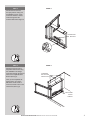
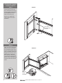
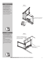
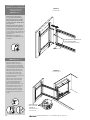
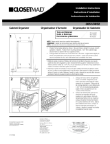
Pull the Swivel Frame into
the open position. Using 2 of
the M5x8mm screws, attach
Connector Bracket to Swivel
Frame through the hole
locations illustrated in Figure 3.
STEP 3
Attach the Swivel Frame to
Adjustable Side Bracket using
the 3 M5x8mm Hex Flange
Cross Bolts through the slotted
holes on the Adjustable Side
Bracket (See Fig 4).
Once you have adjusted the
Swivel Frame, use 2 of the
M4x18mm wood screws to
secure the Swivel Frame to the
cabinet oor (See Fig 4).
STEP 4
FIGURE 3
FIGURE 4
CONNECTOR
BRACKET
3 M5X8MM
HEX FLANGE
CROSS BOLTS
2 M4X18MM
WOOD
SCREWS
2/3
10-3/4”
7-9/16”
14-11/16”
7-9/16”
1/2”
Between
15-24”

Customer Service: 800-626-1126 | rev-a-shelf.com
4
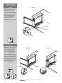
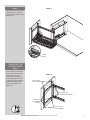
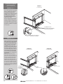
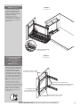
With the Swivel Frame in the
open position, locate the
two holes on the backside of
the frame. Using the 2 M4x6
Machine Screws, attach the
Handle Bracket. See Figure
5 for the Handle Bracket’s
installation position.
NOTE: leave unit in the open
position for step 6.
Remove the screw from the
black bumper on the Support
Arm and set pieces to the
side. Place the Support Arm
on top of Handle Bracket and
secure using the M5x8mm
screw (See Fig 6A). Place the
opposite end of the Support
Arm under the slotted portion
of the Connector, re-attach
the black bumper pieces with
the removed screw from the
beginning of this step and
secure. (See Fig 6B)
FIGURE 5
FIGURE 6A FIGURE 6B
M5x8MM
SCREW
BUMPER
PIECES
BUMPER
PIECES
STEP 5
ATTACHING THE
FRAME (CONT’D)
2/3
10-3/4”
7-9/16”
14-11/16”
7-9/16”
1/2”
Between
15-24”
STEP 6
2 M4x6MM
MACHINE
SCREWS
HANDLE
BRACKET
#2

LONGER
ADDITIONAL TOP
BRACKETS HAVE
BEEN PROVIDED
FOR TALLER DOOR
APPLICATIONS.

Customer Service: 800-626-1126 | rev-a-shelf.com
6
Insert the Door Frame with
door attached into the Swivel
Frame as shown. Secure using
2 of the M6x12mm button
head screws (See Fig 9).
NOTE: Door adjustments
can be made at the end of
installation.
Open your unit to the desired
position. After removing the
pre-assembled stopper screw
from its accompanying pieces,
place the bottom piece of the
Stopper Screw in front of the
black bumper, underneath
the Connector’s slot (See Fig
10). Place the remaining two
pieces on top of the Connector
and secure with the removed
screw.
FIGURE 9
FIGURE 10
STEP 9
ATTACHING CABINET
DOOR (CONT’D)
M6x12MM
BUTTON HEAD
SCREWS
STEP 10
STOPPER
SCREW
ASSEMBLY
#2

INSTALLATION INSTRUCTIONS: 5708 ABOVE THE APPLIANCE ORGANIZER 7
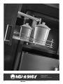
Hang Wire Basket on the lower
hooks (See Fig11). Hang the
basket from the 2nd wire down
from the top.
STEP 11
FIGURE 11
FIGURE 12
Use the screws on both sides
of the swivel frame mounting
screws to tilt your door
horizontally. Use the screws
already attached to the door
to adjust your door vertically.
Adjust as needed to t the
door to your cabinet. (See
Figure 12)
STEP 12
ADJUSTING THE
CABINET DOOR
LOWER
HOOKS
LEFT/RIGHT TILT
ADJUSTMENT SCREWS
SIDE TO SIDE
ADJUSTMENTS
SIDE TO SIDE
ADJUSTMENTS
4 VERTICAL
ADJUSTMENT
SCREWS

Customer Service: 800-626-1126 | rev-a-shelf.com
8
12400 Earl Jones Way
Louisville, KY 40299
rev-a-shelf.com
Customer Service: 800-626-1126

INSTRUCCIONES DE INSTALACIÓN: ORGANIZADOR SUPERIOR PARA ELECTRODOMÉSTICOS
INSTRUCTIONS D’INSTALLATION: ORGANIZADOR SUPERIOR PARA ELECTRODOMÉSTICOS
12400 Earl Jones Way
Louisville, KY 40299
rev-a-shelf.com
Customer Service: 800-626-1126
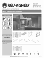
ORGANIZADOR SUPERIOR PARA ELECTRODOMÉSTICOS
ORGANISATEUR 5708 AU-DESSUS DES APPAREILS
HERRAMIENTAS REQUERIDAS:
OUTILS REQUIS:
20 MIN
TIEMPO ESTIMADO
DE ENSAMBLADO:
CUIDADO Y MANTENIMIENTO
Limpie con un paño húmedo y
seque bien las partes.
Nettoyez avec un linge humide et
essuyez les pièces pour les sécher
complètement.
I-5708-TRI-0216
3
32
#2
20150914-1
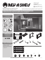
Fittings
No.
Description Qty
1
Door Stopper
1
2 M6x12mm button head screw 2
3
M5x8mm hex flange cross bolt
3
4 M5x8mm bolt 2
5
5/32x18 wood screw 14
6 M4x6 Screw
2
7 M5x8.5mm bolt 1
Component
No.
Description Qty
A
Wire Basket
1
B Door frame 1
C Swivel frame 1
D
Adjustable Side Bracket
1
E Connecter 1
F
Support Arm
1
G Handle bracket 1
H
Up Bracket
2
I
Down Bracket
4
E
C
D
2
3
4
6
7
1
F
5
1/3
G
H
B
A
I
20150914-1
Fittings
No.
Description Qty
1
Door Stopper
1
2 M6x12mm button head screw 2
3
M5x8mm hex flange cross bolt
3
4 M5x8mm bolt 2
5
5/32x18 wood screw 14
6 M4x6 Screw
2
7 M5x8.5mm bolt 1
Component
No.
Description Qty
A
Wire Basket
1
B Door frame 1
C Swivel frame 1
D
Adjustable Side Bracket
1
E Connecter 1
F
Support Arm
1
G Handle bracket 1
H
Up Bracket
2
I
Down Bracket
4
E
C
D
2
3
4
6
7
1
F
5
1/3
G
H
B
A
I
Canasta de Alambre/Panier en l métallique
Marco de la Puerta/Cadre de la Porte
Marco Giratorio/Cadre Pivotant
Soporte Alto/Support du Haut
Soporte Bajo/Support du Bas
Soporte Lateral Ajustable/Support de Côté Réglable
Conector Del Soporte/Support Du Connecteur
Brazo de Soporte/Bras de Support
Soporte de Manija/Support pour la Poignée
Descripción/Description
Componentes/Éléments
INSTRUCCIONES EN VIDEO: WWW.REV-A-SHELF.COM/VIDEOS
VIDÉO DES INSTRUCTIONS: WWW.REV-A-SHELF.COM/VIDEOS
INSTRUCCIONES DE INSTALACIÓN
INSTRUCTIONS D’INSTALLATION
DURÉE ESTIMÉE DE
L’ASSEMBLAGE:
ENTRETIEN ET MAINTENANCE :
Accesorios/Raccords
No.
Descripción/Description
Qty
1
Tornillo de Tope/Vis d’Arrêt
1
2
Tornillo de cabeza de botón de M6x12mm
Vis à tête bombée M6x12mm Vis d’Arrêt
2
3
Perno de reborde de cruz hexagonal de M5x8mm
Boulon hexagonal à bride en croix M5x8mm
3
4
Perno de M5x8mm/Boulon M5x8mm
2
5
Tornillo de madera 5/32x18/Vis à bois 5/32x18
14
6
Tornillo M4x6/Vis M4x6
2
7
Perno M5x8.5mm/Vis M4x6
1

10
Vea la gura 1 para todas las
ubicaciones a taladrar para la parte
interior del gabinete. Use un lápiz
para marcar los tres oricios de las
paredes laterales antes de taladrar.
NOTA: Si usted está instalando
dentro de un gabinete sin
marco, usted debe añadir ¾” de
profundidad a las dimensiones que
se muestran.
Voir l’Illustration 1 pour tous les
emplacements de perçage pour
l’intérieur de votre armoire. Utilisez
un crayon pour marquer les 3 trous
de la paroi de côté avant de percer.
REMARQUE: Si vous installez dans
une armoire sans cadre, vous devez
ajouter ¾” (1.9cm) aux dimensions
de profondeur indiquées.
Sujete los soportes laterales
ajustables a la pared del gabinete
utilizando tres tornillos de madera
de M4 x 18mm (ver la gura 2).
El soporte ajustable debe estar
colocado al ras con la parte de
atrás del marco o a ¾” de la parte
delantera de la pared del gabinete
sin marco.
Fixez les supports de côté réglables
sur la paroi de l’armoire avec 3
des vis à bois M4 x 18mm (voir
l’Illustration 2). Le support réglable
doit être à ras de l’arrière du
cadrage avant ou à ¾” (1.9cm) de
l’avant de la paroi d’une armoire
sans cadre.
FIGURA 1
ILLUSTRATION 1
FIGURA 2
ILLUSTRATION 2
SOPORTE AJUSTABLE
SUPPORTS RÉGLABLES
PASO 1/ÉTAPE 1
DIMENSIONES DE LA PARED
LATERAL DEL GABINETE
DIMENSIONS DU CÔTÉ DE LA
PAROI DE L’ARMOIRE
PASO 2/ÉTAPE 2
SUJETANDO EL MARCO
FIXER LE CADRE
2/3
10-3/4”
7-9/16”
14-11/16”
7-9/16”
1/2”
Between
15-24”
2/3
10-3/4”
7-9/16”
14-11/16”
7-9/16”
1/2”
Between
15-24”
3
32
#2
PARED POSTERIOR DEL GABINETE
PAROI ARRIÈRE DE L’ARMOIRE
Servicio al Cliente/Service client: 800-626-1126 | rev-a-shelf.com

11
2/3
10-3/4”
7-9/16”
14-11/16”
7-9/16”
1/2”
Between
15-24”
Jale el marco giratorio en la
posición abierta. Utilizando
dos tornillos M5x8mm, sujete
el conector del soporte al
marco giratorio a través de
las ubicaciones de los oricios
ilustrados en la gura 3.
Tirez le cadre pivotant en position
ouverte. À l’aide de 2 des vis
M5x8mm, xez le support du
connecteur sur le cadre pivotant à
travers les emplacements des trous
illustrés dans l’Illustration 3.
PASO 1/ÉTAPE 1
Sujete el marco giratorio al
soporte lateral ajustable utilizando
tres pernos de reborde de cruz
hexagonal de M5x8mm a través
de las ranuras de los oricios en los
soportes laterales ajustables (Ver la
gura 4).
Fixez le cadre pivotant sur le
support de côté réglable en
utilisant les 3 boulons hexagonaux
à bride en croix M5x8mm à travers
les trous rainurés sur le support
réglable de côté (voir l’Illustration
4).
STEP 4
FIGURA 4
ILLUSTRATION 4
FIGURA 3
ILLUSTRATION 3
CONECTOR DEL SOPORTE
SUPPORT DU CONNECTEUR
3 PERNOS DE REBORDE DE CRUZ
HEXAGONAL DE M5X8MM
3 BOULONS HEXAGONAUX A
BRIDE EN CROIX M5X8MM
2 TORNILLOS DE MADERA
DE M4X18MM
2 VIS À BOIS M4X18MM
2/3
10-3/4”
7-9/16”
14-11/16”
7-9/16”
1/2”
Between
15-24”
INSTRUCCIONES DE INSTALACIÓN: ORGANIZADOR SUPERIOR PARA ELECTRODOMÉSTICOS
INSTRUCTIONS D’INSTALLATION: ORGANIZADOR SUPERIOR PARA ELECTRODOMÉSTICOS

12
Con el marco giratorio en posición
abierta, localice los dos oricios
en la parte trasera del marco.
Utilizando dos tornillos de máquina
de M4x6, sujete el soporte de
la manija. Ver la gura 2 para
la instalación de la posición del
soporte de la manija.
Avec le cadre pivotant en position
ouverte, repérez les deux trous à
l’arrière du cadre. En utilisant les 2
vis machine M4x6, xez le support
de poignée. Voir l’Illustration 2 pour
la position d’installation du support
de la poignée.
Quite el tornillo del tope negro del
brazo del soporte y deje las partes
a los lados. Coloque el brazo del
soporte encima del soporte de la
manija y asegure con el tornillo
de M5x8mm (Ver la gura 6A).
Coloque el lado opuesto del brazo
del soporte debajo de la porción
con ranuras del conector, vuelva a
sujetar las piezas del tope negro
con el tornillo que quitó desde el
inicio de este paso y asegure (Ver
la gura 6B).
Retirez la vis du butoir noir sur
le bras de soutien et mettez les
pièces sur le côté. Placez le bras de
soutien sur le dessus du support
de la poignée et xez avec la vis
M5x8mm (Voir l’Illustration 6A).
Placez l’extrémité opposée du bras
de soutien sous la partie rainurée
du connecteur, rattachez les pièces
du butoir noir avec la vis enlevée au
début de cette étape et xez. (Voir
l’Illustration 6B).
TORNILLO DE
M5X8MM
VIS M5X8MM
TOPES
PIÈCES DU BUTOIR
TOPES
PIÈCES DU BUTOIR
PASO 5/ÉTAPE 5
SUJETANDO EL MARCO
(CONTINUACIÓN)
FIXER LE CADRE (SUITE)
2/3
10-3/4”
7-9/16”
14-11/16”
7-9/16”
1/2”
Between
15-24”
PASO 6/ÉTAPE 6
2 TORNILLOS DE
MÁQUINA DE M4X6MM
2 VIS MACHINE M4X6MM
SOPORTE DE MANIJA
SUPPORT DE LA POIGNÉE
#2
Servicio al Cliente/Service client: 800-626-1126 | rev-a-shelf.com
FIGURA 5
ILLUSTRATION 5
FIGURA 6A
ILLUSTRATION 6A
FIGURA 6B
ILLUSTRATION 6B

13
Reérase a la gura 7 para las
dimensiones de la perforación.
Una vez que usted haya marcado
las ubicaciones de los oricios,
pre taladre oricios piloto
asegurándose de no taladrar a
través del frente de la puerta del
gabinete.
NOTA: Usted debe montar los
soportes de la puerta dentro de la
porción gruesa de la puerta.
Pour les dimensions de forage,
reportez-vous à l’Illustration 7. Une
fois que vous avez marqué vos
emplacements des trous de forage,
pré-percez des trous pilote en
étant sûr de ne pas percer à travers
l’avant de votre porte de l’armoire.
REMARQUE: Vous devez monter
les supports de porte dans la partie
épaisse de votre porte.
Inserte los soportes superiores en
la parte superior del marco de la
puerta y los soportes inferiores
en la parte inferior del marco de
la puerta. De forma temporal,
asegure utilizando los pernos que
ya están sujetos al marco de la
puerta (ver la gura 8). Asegure el
marco de la puerta a la puerta del
gabinete utilizando cuatro tornillos
de madera de M4x18mm.
Insérez les supports du dessus
dans le haut du cadre de la porte
et les supports du bas dans le
bas du cadre de la porte. Fixez
temporairement en utilisant les
boulons déjà attachés au cadre
de la porte (voir l’Illustration 8).
Fixez le cadre de la porte à la
porte de l’armoire avec 4 vis à bois
M4x18mm.
4 TORNILLOS DE
MADERA DE M4X18MM
4 VIS À BOIS M4X18MM
EL PERNO YA ESTÁ
SUJETO AL MARCO
BOULON DÉJÀ FIXÉ AU
CADRE
SOPORTE DE LA PUERTA
SUPPORT DE PORTE
SUJETANDO LA
PUERTA DEL GABINETE
FIXER LA PORTE DE L’ARMOIRE
2/3
10-3/4”
7-9/16”
14-11/16”
7-9/16”
1/2”
Between
15-24”
2/3
10-3/4”
7-9/16”
14-11/16”
7-9/16”
1/2”
Between
15-24”
2/3
10-3/4”
7-9/16”
14-11/16”
7-9/16”
1/2”
Between
15-24”
#2
LA ALTURA PUEDE SER
ENTRE 15” Y 24”. CUANDO
SELECCIONE EL PUNTO A
TALADREAR, MIDA POR EL
CENTRO DEL MARCO DE SU
GABINETE.
LA HAUTEUR PEUT SE SITUER ENTRE
15” (38.1CM) ET 24” (60.9CM).
LORSQUE VOUS CHOISISSEZ VOTRE
POINT DE FORAGE, MESUREZ POUR
LE CENTRE DU CADRE DE VOTRE
ARMOIRE.
3
32
PASO 7/ÉTAPE 7
PASO 8/ÉTAPE 8
INSTRUCCIONES DE INSTALACIÓN: ORGANIZADOR SUPERIOR PARA ELECTRODOMÉSTICOS
INSTRUCTIONS D’INSTALLATION: ORGANIZADOR SUPERIOR PARA ELECTRODOMÉSTICOS
FIGURA 7
ILLUSTRATION 7
FIGURA 8
ILLUSTRATION 8

14
Inserte el marco de la puerta
con la puerta sujeta dentro del
marco giratorio como se muestra.
Asegure, utilizando dos tornillos
de cabeza de botón de M6x12mm
(ver la gura 9).
NOTA: Se pueden hacer ajustes a
la puerta al nal de la instalación.
Insérez le cadre de la porte avec la
porte xée dans le cadre pivotant
comme indiqué. Fixez à l’aide des 2
vis à tête bombée M6x12mm (voir
l’Illustration 9).
REMARQUE: Les réglages de
porte peuvent être faits à la n de
l’installation.
Abra la unidad a la posición
deseada. Después de quitar el
tornillo del tope pre ensamblado
con las piezas que lo acompañan,
coloque la pieza inferior del tornillo
del tope en frente del tope, por
debajo del espacio del conector
(ver la gura 10). Coloque las
dos piezas sobrantes en la parte
superior del conector y asegure con
el tornillo removido.
Ouvrez votre unité à la position
désirée. Après avoir retiré la vis
du butoir préassemblé de ses
pièces d’accompagnement,
placez la pièce du bas de la vis du
butoir devant le butoir noir, sous
la rainure du Connecteur (voir
l’Illustration 10). Placez les deux
morceaux restants sur le dessus
du connecteur et xez avec la vis
retirée.
SUJETANDO LA PUERTA DEL
GABINETE (CONTINUACIÓN)
FIXER LA PORTE DE
L’ARMOIRE (SUITE)
TORNILLOS DE CABEZA DE
BOTÓN M6X12MM
VIS À TÊTE BOMBÉE M6X12MM
ENSAMBLADO
DEL TOPE DEL
TORNILLO
ASSEMBLAGE DE LA
VIS DU BUTOIR
#2
PASO 7/ÉTAPE 7
PASO 9/ÉTAPE 9
PASO 10/ÉTAPE 10
Servicio al Cliente/Service client: 800-626-1126 | rev-a-shelf.com
FIGURA 9
ILLUSTRATION 9
FIGURA 10
ILLUSTRATION 10

15
Cuelgue la canasta de alambre
en los ganchos inferiores (ver la
gura 11). Cuelgue la canasta
del segundo alambre hacia abajo
desde la parte superior.
Suspendez le panier en l
métallique sur les crochets du bas
(voir l’Illustration 11). Suspendez
le panier du deuxième support à
partir du haut.
Utilice los tornillos en ambos lados
del marco giratorio montando los
tornillos para inclinar la puerta
horizontalmente. Para ajustar la
puerta de manera vertical, utilice
los tornillos que ya están sujetos al
soporte de la puerta. Ajuste como
sea necesario para adaptarse a la
puerta de su gabinete (ver la gura
12).
Utilisez les vis sur les deux côtés
des vis de montage du cadre
pivotant pour incliner votre porte
horizontalement. Utilisez les vis déjà
attachées au support de porte pour
régler votre porte verticalement.
Réglez au besoin pour adapter
la porte dans votre armoire. (Voir
l’Illustration 12)
AJUSTANDO LA PUERTA
DEL GABINETE
RÉGLER LA PORTE DE
L’ARMOIRE
GANCHOS INFERIORES
CROCHETS DU BAS
TORNILLOS DE AJUSTE PARA
INCLINACIÓN DERECHA/IZQUIERDA VIS
DE RÉGLAGE D’INCLINAISON GAUCHE/DROITE
AJUSTES DE LADO A LADO
RÉGLAGE D’UN CÔTÉ À L’AUTRE
AJUSTES DE LADO A LADO
RÉGLAGE D’UN CÔTÉ À L’AUTRE
4 TORNILLOS PARA
AJUSTES VERTICALES
4 VIS DE RÉGLAGE VERTICAL
PASO 11/ÉTAPE 11
PASO 12/ÉTAPE 12
INSTRUCCIONES DE INSTALACIÓN: ORGANIZADOR SUPERIOR PARA ELECTRODOMÉSTICOS
INSTRUCTIONS D’INSTALLATION: ORGANIZADOR SUPERIOR PARA ELECTRODOMÉSTICOS
FIGURA 11
ILLUSTRATION 11
FIGURA 12
ILLUSTRATION 12

16
12400 Earl Jones Way
Louisville, KY 40299
rev-a-shelf.com
Customer Service: 800-626-1126
Servicio al Cliente/Service client: 800-626-1126 | rev-a-shelf.com
-
 1
1
-
 2
2
-
 3
3
-
 4
4
-
 5
5
-
 6
6
-
 7
7
-
 8
8
-
 9
9
-
 10
10
-
 11
11
-
 12
12
-
 13
13
-
 14
14
-
 15
15
-
 16
16


Rev-A-Shelf 5708-15CR Installation Instructions Manual
- Taper
- Installation Instructions Manual
- Ce manuel convient également à
dans d''autres langues
- English: Rev-A-Shelf 5708-15CR
- español: Rev-A-Shelf 5708-15CR
Documents connexes
-
Rev-A-Shelf 5708-15CR Instruction Sheet
-
-
-
-
-
-
-
-
-
Autres documents
-
 ClosetMaid 53052 Guide d'installation
-
 ClosetMaid 11 In. Cabinet Organizer Guide d'installation
-
Pleasant Hearth OFW316RAN Manuel utilisateur
-
Mounting Dream MD5109-KD Manuel utilisateur
-
HPI Racing Savage Flux 2350 Manuel utilisateur
-
-
-

