LG LP120CEDC Le manuel du propriétaire
- Catégorie
- Climatiseurs split-system
- Taper
- Le manuel du propriétaire
Ce manuel convient également à

LG
Package terminal air conditioner
OWNER'S MANUAL
Climatiseur de fenêtre
MANUEL D'UTILISATION
LG
website http://www.lg.ca
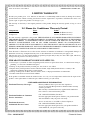
Please read the operating instructions and safety precautions carefully
and thoroughly before installing and operating your room air conditioner.
Veuillez lire attentivement et en entier ce guide d’utilisation et les
mesures de sécurité ci-incluses avant de procéder à l’installation et au
fonctionnement de votre climatiseur.
IMPORTANT
Please read through this manual. It contains valuable
information about your air conditioner. This manual
may help save time and money by explaining proper
air conditioner maintenance and preventing improper
use.
ENGLISH FRANÇAIS

2 Room Air Conditioner
Packaged Terminal Air Conditioner/Heat Pump Owner's Manual
TABLE OF CONTENTS
FOR YOUR RECORDS
Write the model and serial numbers here:
Model #
Serial #
You can find them on a label on the side of each unit.
Dealer's Name
Date Purchased
■ Staple your receipt to this page in the event you need it
to prove date of purchase or for warranty issues.
READ THIS MANUAL
Inside you will find many helpful hints on how to use and
maintain your air conditioner properly. Just a little
preventive care on your part can save you a great deal of
time and money over the life of your air conditioner.
You'll find many answers to common problems in the chart
of troubleshooting tips. If you review our chart of
Troubleshooting Tips first, you may not need to call for
service at all.
PRECAUTION
• Contact an authorized service technician for repair or
maintenance of this unit.
• For installation problems.
• The air conditioner is not intended for use by young
children or invalids without supervision.
• Young children should be supervised to ensure that
they do not play with the air conditioner.
• When the power cord is to be replaced, replacement
work shall be performed by authorized personnel
only using only genuine replacement parts.
• Installation work must be performed in accordance
with the National Electric Code or the Canadian
Electrical Code, all applicable Federal, State,
Provincial, Municipal and Fire codes and ordinances.
This work must be done by qualified and authorized
personnel only.
Safety Precautions..........................3
Before Operation.............................7
Introduction ....................................8
Electrical Safety ..............................9
Installation ....................................10
Control Locations..........................12
Maintenance and Service ............18

ENGLISH
Owner’s Manual 3
Safety Precautions
Safety Precautions
To prevent injury to the users or other people, or property damage, the following instructions
must be followed.
■ Incorrect operation due to ignoring these instructions may cause harm or damage. The
seriousness is classified by the following indications:
■ Meanings of symbols used in this manual are as shown below.
WARNING
CAUTION
This symbol indicates the possibility of death or serious injury.
This symbol indicates the possibility of injury or damage to properties only.
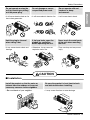
WARNING
■ Installation
Don't do this!
Be sure to follow the instruction.
Don’t use a power cord, a
plug, or a loose socket
which is damaged.
• It may cause a fire or electrical
shock.
Always plug into a grounded
outlet.
• It may cause a fire or electrical
shock.
Do not modify or extend the
power cord length.
• It will cause electric shock or fire
due to heat generation.
Do not disassemble or
modify products.
• It may cause failure and
electric shock.
Be caution when unpacking
and installing.
• Sharp edges may cause
injury.
Do not use the power cord near
flammable gas or combustibles
such as gasoline, benzene,
thinner, etc.
• It may cause explosion or fire.
Gasolin

4 Room Air Conditioner
Safety Precautions
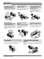
■ Operation
Do not place the power cord
near a heater.
• It may cause fire and electric
shock.
Do not allow water to run
into electric parts.
• It will cause failure of machine or
electric shock.
Use a soft cloth to clean. Do
not use wax, thinner, or a
strong detergent.
• The appearance of the air
conditioner may deteriorate,
change color, or develop
surface flaws.
Wax
Thinner
Ventilate the room well when
using this appliance
together with a stove, etc.
• Oxygen depletion could occur.
Turn off the power and
breaker when cleaning the
unit.
• Moving parts could cause injury.
Turn off the main power
switch when not using it for
a long time.
• Prevent accidental startup and
the possibility of injury.
Unplug the unit if strange
sounds, odors, or smoke
come from it.
• It could represent a fire hazed.
Do not open the air inlet grill
of the product during
operation.
• Otherwise, it may electrical
shock and failure.
If water enters the product, turn
off the the power switch of the
main body of appliance. Contact
service center after taking the
power plug out from the socket.
Do not place objects on the
power cord. Protect the cord
from being pinched or
damaged.
• There is danger of fire or electric
shock.
Use a dedicated circuit for
this appliance.
• An overloaded circuit is a fire
hazard.
Take the power plug out if
necessary, holding the end
of the plug and do not touch
it with wet hands.
• It may cause a fire or electrical
shock.

ENGLISH
Owner’s Manual 5
Safety Precautions
CAUTION
■ Installation
Do not operate or stop the
unit by inserting or pulling
out the power plug.
• It will cause electric shock or fire
due to heat generation.
Do not damage or use an
unspecified power cord.
• It will cause electric shock or fire.
Do not operate with wet
hands or in damp
environment.
• It will cause electric shock.
Hold the plug by the end
when taking it out.
• It may cause electric shock and
damage.
If fuel gas leaks, open the
window for ventilation
before operating the unit.
• Otherwise, it may cause an
explosion and a fire.
Never touch the metal parts
of the unit when removing
the filter.
• They are sharp and may cause
injury.
Install the product so that the noise or
exhaust from the outdoor unit may not
cause any concerns to the neighbors.
• Be considerate of your neighbor.
Be sure the product is level front-to-back
and side-to-side when installing.
• It may cause vibration or water leakage.

6 Room Air Conditioner
Safety Precautions
■ Operation
Be cautious not to touch the sharp edges
when installing.
• A severe cut or other injury could result.
Do not insert hands or other objects
through the air inlet or outlet during
operation.
• Electrical and moving parts could cause shock or
injury.
Do not put a pet or house
plant where it will be
exposed to direct air flow.
• It is not good to sit in the draft.
Do not block the inlet or
outlet of air flow.
• It may cause product failure.
Use a soft cloth to clean. Do
not use wax, thinner, or a
strong detergent.
• The appearance of the air
conditioner may deteriorate,
change color, or develop surface
flaws.
Do not step on the
indoor/outdoor unit and do
not put anything on it.
• It may cause an injury through
dropping of the unit or falling
down.
Always insert the filter
securely.
Clean it every two weeks.
• Operation without filters will
cause failure.
Do not drink water drained
from the air conditioner.
• This could cause health issues.

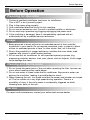
Before Operation
Owner’s Manual 7
ENGLISH
Before Operation
1. Contact a qualified installation contractor for installation.
This is NOT a do-it-yourself project.
2. Plug in the power plug properly.
3. Use a dedicated electrical circuit for this machine.
4. Do not use an extension cord. Consult a qualifed installer or electrician.
5. Do not start/stop operation by plugging/unplugging the power cord.
6. If the cord/plug is damaged, have it immeadiateley replaced with an
authorized part by a qualified service technician.
1. Being exposed to direct airflow for an extended period of time could be
hazardous to your health. Do not expose occupants, pets, or plants to direct
airflow for extended periods of time. In other words, don't sit in the draft.
2. Due to the possibility of oxygen deficiency, ventilate the room when used
together with stoves or other heating devices.
3. Do not use this air conditioner for non-specified special purposes (e.g.
preserving precision devices, food, pets, plants, and art objects). Such usage
could damage the items.
1. Do not touch the metal parts of the unit when removing the filter. Injuries can
occur when handling sharp metal edges.
2. Do not use water to clean inside the air conditioner. Exposure to water can
destroy the insulation, leading to possible electric shock.
3. When cleaning the unit, first make sure that the power and breaker are turned
off. The fan rotates at a very high speed during operation. There is a
possibility of injury if the unit’s power is accidentally triggered on while
cleaning inner parts of the unit.
For repair and maintenance, contact your authorized service dealer.
Preparing for Operation
Usage
Cleaning and Maintenance
Service

8 Room Air Conditioner
Introduction
This symbol alerts you to the risk of electric shock.
This symbol alerts you to hazards that could cause harm to
the air conditioner.
This symbol indicates special notes.
NOTICE
This appliance should be installed in accordance with the National Electric Code or in Canada, the
Canadian Electric Code and applicable Federal, State, Provincial, Municipal and Fire codes and oridnances.
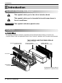
Introduction
Symbols Used in this Manual
Features
IN
D
O
O
R
REAR GRILLE
(Aluminum Rear Grille)
EXPANDED METAL GRILLE
(Superior for a performance)
SLEEVE ASSEMBLY
(Including Aluminum Rear Grille)
THE SLEEVE AND THE REAR GRILLE
(Available as an option)
VERTICAL AIR DEFLECTOR
(Horizontal Louver)
AIR FILTER
INLET GRILLE
(Air Intake)

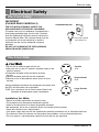
Electrical Safety
Owner’s Manual 9
ENGLISH
Electrical Safety
Electrical Safety
Electrical Data
PREFERRED METHOD
Ensure proper ground
exists before use
Tandem
15 A
Perpendicular
20 A
Large Tandem
30 A
IMPORTANT
(PLEASE READ CAREFULLY)
FOR THE USER'S PERSONAL SAFETY, THIS
APPLIANCE MUST BE PROPERLY GROUNDED
The power cord of this air conditioner is equipped with a
three-prong (grounding) plug. Use this with a standard
three-slot (grounding) wall power outlet to minimize the
hazard of electric shock. The customer should have the
wall receptacle and circuit checked by a qualified
electrician to make sure the receptacle is properly
grounded.
DO NOT CUT OR REMOVE THE THIRD (GROUND)
PRONG FROM THE POWER PLUG.
1.Do not use an extension cord with this unit.
2.When the unit is in the OFF position, the power supply to the
electrical controls.
3.Disconnect the power to the unit before servicing
the unit.
4.Remove the power cord from the wall receptacle.
5.Remove or turn off the protective device (fuses or circuit
breaker).
Wirings including installation of the receptacle must comply with
the NEC and local codes, local regulations.
FUSE- Use a time-delay fuse or circuit breaker. Refer to the
nameplate for proper power supply requirements.
Installation (for 60Hz)
• Electric installation requirement for personal safety:
• This equipment must be properly connected to ground.
• Under no circumstances cut or break the grounder conductor.
• We recommend not to use an extension wire or any adaptor with this product.
• Follow the national or local electric codes.
• If the power supply does not fulfill the specifications previously mentioned, call an authorized electrician.
• The aluminum wired in the houses may bring about some problems, call an authorized electrician.
• This unit requires a separated power supply that works only for this application.

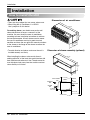
10 Room Air Conditioner
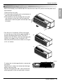
Installation
How to Install the Unit
Installation
406 mm
(16")
406 mm
(16")
1,066 mm
(42")
1066 mm
(42")
318 mm
(12
1
/
2
")
318 mm
(12
1
/
2
")
505 mm
(20")
Over 20"
HEAT
RADIATION
WALL
WALL
INSULATION SLEEVE
INTAKE
AIR
COOLED
AIR
1/4" Bubble
of the level
• There are sharp edges that can cause serious cuts.
• When lifting the air conditioner, it is HEAVY.
Use 2 people to lift this device.
For existing sleeve, you should measure the wall
sleeve dimensions to ensure a correct fit of the
machine, You must install the new air conditioner
according to these installation instructions to achieve
the best performence. All wall sleeves used to mount
the new air conditioner must be in good structural
condition and have the rear grille that securely attaches
to the sleeve or the flange of the sleeve to secure the
new air conditioner.
• To avoid vibration and noise, make sure the unit is
installed securely and firmly.
When installing the sleeve, make certain there is
nothing within 20" of the back that would interfere with
heat radiation and exhaust air flow. The exhausted air
must dissipate freely away from the machine and not
return directly to its intake.
Dimension of air conditioner
Dimension of sleeve assembly (optional)

Owner’s Manual 11
ENGLISH
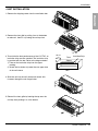
Installation
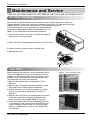
• UNIT INSTALLATION
1. Remove the shipping screw from the ventilation door.
2. Remove the front gille by pulling it out at the bottom
to release it, then lift it up along the unit top front.
3. To maintain the best performance of the LG PTAC, an
insulation strip must be attached. The insulation strip
is provided with the box. Refer to the diagram below.
1) Take out the insulation strip from the upper
packing.
2) Attach the insulation strip onto the rear upper side
of the wall sleeve.
4. Slide the unit into the wall sleeve and secure with
6 screws through the unit flange holes.
5. Reinstall the front grille by hooking the top over the
unit top, then pushing it in at the bottom.
Front
Insulation Strip
Rear
Sleeve
280 mm
(11")

12 Room Air Conditioner
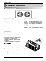
Control Locations
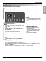
Control Locations
Manual Controls
TEMPERATURE CONTROL
Set the Thermostat control to the desired
temperature mark 5 (the mid-point is a good
starting position). If the room temperature is not
satisfactory after a reasonable time, adjust the
control to a cooler or warmer setting, as
appropriate.
OPERATION MODE SELECTOR
OFF Turns air conditioner off.
LOW FAN Low speed fan operation without cooling.
HIGH FAN High speed fan operation without cooling.
LOW COOL Cooling with the low speed fan operation.
HIGH COOL Cooling with the high speed fan operation.
LOW HEAT Heating with the low speed fan operation.
HIGH HEAT Heating with the high speed fan operation.
• VENTILATION
The ventilation lever is located to the lower left side
of the unit.
The ventilation lever must be in the CLOSE position in
order to maintain the best cooling conditions.
When fresh air is necessary in the room, set the
ventilation lever to the OPEN position.
The damper is opened and outdoor air is drawn
into the room.
This will reduce the cooling or heating efficiency.
When the air conditioner has been running and is
turned off or set to the fan position, wait at least 3
minutes before resetting to the cooling operation.
Note:
A slight heat odor may come from the unit
when first switching to HEAT after the
cooling season is over.
This odor, caused by fine dust particles on
the heater, will disappear quickly.
This is harmless.
VENT
OPEN
VENT
CLOSE

Owner’s Manual 13
ENGLISH
Control Locations
Electronic Controls
The controls will look like one of the following.
TEMP
MODE
HEAT
E/SAVE
FANFAN
COOLCOOL
HIGHHIGH
LOWLOW TIMERTIMER
FAN TIMER
°C
ON
OFF
ON
OFF
POWER
MODE
-
Push this button to cycle through the modes from COOL → FAN
→ HEAT→ COOL.
- COOL
• Fan runs continually for normal cooling operation.
- ENERGY SAVER
• The fan stops when the compressor stops cooling.
Approximately every 3 minutes the fan will turn on and the unit
will check the room air temperature to determine if cooling is
needed.
- FAN
• Fan operation without heating or cooling.
- HEAT
• Fan runs continually for normal heating operation.
TIMER
- SHUT-OFF TIME
• You will usually use shut-off time while you sleep.
• If unit is running, use Timer to set number of hours until shut-off.
• For your sleeping comfort, once Time is set, the Temperature setting will raise 2°F(1°C) after 30 minutes, and once
again after another 30 minutes.
• Push Timer to cycle through the settings from 1 Hour → 2 Hours → ... → 12 Hours maximum.
TEMPERATURE SETTING
• Use this button to automatically control the
temperature of the room.
The temperature can be set within a range of
54°F(12°C) to 86°F(30°C) by increments of
2°F(1°C).
• The setting appears in the display.
FAN SPEED
• Every time you push this button, it cycles through the settings as follows:
{High(F2) → Low(F1) → High(F2) → Low(F1)}
• To turn the air conditioner ON, push this button.
To turn the air conditioner OFF, push the button
again.
• This button takes priority over any other button.

14 Room Air Conditioner
Control Locations
Self-Diagnosis
FUNCTION:
If the unit has a malfunction, a green OPERATION LED located on the Display PCB used by the unit to
indicate the errors.
USE:
If the customer has to call the service center about a service conern, he can be very clear about the
problem by referring the user's manual the customer. This way they can clearly define the problem and
obtain quick service as the techinican will be fylly prepared with the correct tools and parts.
Here are some of the problems defined below for which the LED indicates by flashing number of times
the error has been reconrded against it.
These error codes are the mentioned in the table below:
ON Normal
OFF No power / failed board
Fault Codes
CH 01 Indoor Air Thermistor Error
CH 02 Indoor Coil Thermistor Error
CH 03 Outdoor Air Thermistor Error (PTHP Only)
CH 04 Outdoor Coil Thermistor Error (PTHP Only)
CH 05 Mode Error
CH 06 Setpoint Error
CH 07 Bad Thermistor Wiring

Owner’s Manual 15
ENGLISH
Control Locations
Additional Controls
• REMOVING THE FRONT GRILLE
Additional controls are available after
removing the front grille and option
cover of control box.
To remove the front grille, pull out the
bottom of front grille and then lift up.
To replace the front grille, place the tabs
over the top of the unit and push the
bottom of front grille until the clips snap
into place.
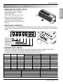
• ADDITIONAL CONTROLS
The additional controls are located behind the option cover of control box. The standard settings will be in
the OFF position. The authorized servicer has to check switches and ensure the switches are in the desired
position.
• TEMPERATURE LIMITING
Temperature Limiting can save money by limiting the lowest temperature for cooling and the highest
temperature for heating. The temperature limiting is controlled by switches #1 - #3.
This temperature limiting is not available with the Remote Wall Thermostat.
LOCAL
1
OFF
2
OFF
3
OFF
4
OFF
5
LOCAL
1
OFF
2
OFF
3
OFF
4
OFF
5
LOCAL
1
OFF
2
OFF
3
OFF
4
OFF
5
ON
ONREMOTE
OFF
ON ON ON
Remote/Local
Energy Saver
Temperature Limit 1
Temperature Limit 2
Temperature Limit 3
PTAC/PTHP
UNIT TYPE
LOCALLOCAL
1
OFF
OFF
2
OFF
OFF
3
OFF
OFF
4
OFF
OFF
5
LOCAL
1
OFF
2
OFF
3
OFF
4
OFF
5
LOCAL
LOCAL
1
OFF
OFF
2
OFF
OFF
3
OFF
OFF
4
OFF
OFF
5
LOCAL
1
OFF
2
OFF
3
OFF
4
OFF
5
OFF
6
OFF
7
LOCALLOCAL
1
OFF
OFF
2
OFF
OFF
3
OFF
OFF
4
OFF
OFF
5
LOCAL
1
OFF
2
OFF
3
OFF
4
OFF
5
OFF OFF OFF 54° F (12.2° C) 86° F (30.0° C)
86° F (30.0° C)
86° F (30.0° C)
86° F (30.0° C)
86° F (30.0° C)
86° F (30.0° C)
86° F (30.0° C)
86° F (30.0° C)
54° F (12.2° C)
54° F (12.2° C)
54° F (12.2° C)
54° F (12.2° C)
54° F (12.2° C)
54° F (12.2° C)
54° F (12.2° C)
54° F (12.2° C)
86° F (30.0° C)
ON OFF OFF 56° F (13.3° C)
84° F (28.9° C)
OFF ON OFF 58° F (14.4° C)
82° F (27.8° C)
ON ON OFF 60° F (15.5° C)
80° F (26.7° C)
OFF
OFF ON 62° F (16.6° C)
78° F (25.5° C)
ON OFF ON 64° F (17.7° C)
76° F (24.4° C)
OFF ON ON 66° F (18.9° C) 74° F (23.3° C)
ON ON ON 68° F (20.0° C)
72° F (22.2° C)
Temperature Temperature Temperature
Limit #1 Limit #2 Limit #3
Lowest Temp. Highest Temp. Lowest Temp. Highest Temp.
Cooling Operation
Heating Operation
Cooling+Electric Heater+Heat PumpOFFOFF
Cooling+Electric HeaterONOFF
Cooling Only
Heat Pump Only
Unit Type
ON
OFF
#7
ON
ON
#6

16 Room Air Conditioner
Control Locations
• REMOTE/LOCAL CONTROL
When remote/local switch #1 is on, it allows the unit to operate by the Remote Wall Thermostat.
The unit control by knobs are not active controls.
• ENERGY SAVER
The energy saver switch #2 is on. This switch is set at cycle fan to provide continuous fan operation in cool
or heat modes. When the switch is off the continuous fan allows continuous circulation of room air.
When the switch is on, the fan is on or off with the compressor or with the heater. It may also cycle on and
off intermittently for short periods of times to determine the room temperatue for comfort purposes.
• FRONT DESK CONTROL
When the pair wire is connected to the connector FD2 and FD1, the unit can be turned ON or OFF with a
switch located at the Front Desk Control panel. When the front desk switch is ON, the fan operates
according to the setting without working compressor and heater. When the front desk switch is OFF, the unit
can operate according to the setting of controls.
• REMOTE WALL THERMOSTAT
When the wires are connected, the unit will be controlled
by a remote wall thermostat.
The thermostat connections supply the 24 Volt AC. When
you install the digital/electronic thermostat, you must set it
to 24 Volt AC. See the installation Instruction in this manual
for the Remote Wall Thermostat.
Wiring Schematic for
Remote Heat Pump
Wiring Schematic for
Straight Cool Unit.
Note: The following figures show wiring
schematics for heat pump and straight cool
units with electric heat, respectively.
GL GH O W Y R C
Low Fan
High Fan
Reversing Valve
Heater
Compressor
24 Volt-L
24 Volt-N
Wire # AWG Maximum Length
#22 600 ft (180 m)
#20
900 ft (270 m)
#18 1500 ft (450 m)
#16 2000 ft (610 m)
FD2 FD1 DR2 DR1 MS2 MS1
Front Desk Control
Front Desk Control
Door Switch
Door Switch
Motion Sensor
Motion Sensor
(Molex Housing Spec 396-06V)
(Molex Housing Spec 396-07V)

Owner’s Manual 17
ENGLISH
Control Locations
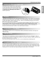
1. Remove the front grille.
2. To remove the front grille, pull out the bottom of
the front grille and then lift up.
3. Re-install the cover by placeing the front grille
over the tabs on the top of the unit and push
the bottom of the front grille until the clips snap
into place.
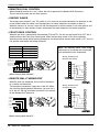
• This Room Air Conditioner (PTAC) discharges
air from the top of the unit through reversible, 2-
position discharge grille louvers. The unit is
shipped from the factory with the discharge grille
louvers at an angle of 40˚ off vertical. In an
alternate position the louvers will be at an angle
of 15˚ off vertical.
To adjust the air discharge direction, remove the
front grille.
Remove the 4 screws that fasten the discharge
grille to the front grille.
Flip the discharge grille 180°, then reattach the
discharge grille to the front grille with 4 screws.
Disassembly Instructions
- Before disassembly, the POWER SWITCH must be set to the OFF position and the power cord
disconnected.
40˚
15˚
Screws

18 Room Air Conditioner
Maintenance and Service
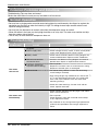
Maintenance and Service
Air Filter Cleaning
Vent Filter
TURN THE AIR CONDITIONER OFF AND REMOVE THE PLUG FROM THE POWER OUTLET.
The air filter should be checked at least twice a month to see if cleaning is necessary.
Trapped particles in the filter will build up and block the airflow. This reduces the cooling
capacity and also causes an accumulation of frost on the cooling coils.
If the filter becomes torn or damaged you should replace
immediately. Replacement filters are available from your
dealer, or an authorized customer service centers.
1. Remove the air filter from the front grille assembly by
pulling the air filter up slightly.
2. Wash the filter using lukewarm water below 104°F(40°C).
3. Gently shake the excess water from the filter.
4. Replace the filter.
Before cleaning the vent filter, disconnect power to the
unit by unplugging the power cord at the wall outlet or
subbase, or disconnect power at the fuse box or circuit
breaker. If unit is operated with vent door closed, the
vent filter does not need to be cleaned.
1. Remove the cabinet front as described in Front
Removal.
2. Remove the six screws securing the chassis to the
wall sleeve with a Phillips-Head screwdriver.
3. Slide the chassis out of the wall sleeve far enough
so that the vent filter is accessible as shown in
Figure A.
4. Remove the vent filter by unscrewing the two screws
at the top of the filter and gently pulling the filter
away from the partition panel. Refer to Figure B.
5. Clean and replace the filter by reattaching the hook
to the bottom of the vent door and replacing the two
screws, slide the chassis back into the wall sleeve,
secure it in place with six screws and reinstall the
front cabinet.
Figure A – Vent (Left side of unit)
Figure B – Vent Filter Removal

Owner’s Manual 19
ENGLISH
Maintenance and Service
Chassis
Additional Drainage(Optional)
Cabinet Front
Corrosion Resistant Models
Compressor / Fan Motor
The chassis and refrigeration coils must be cleaned twice annually or more often if the atmospheric
conditions cause large amounts of dirt, debris or lint to be deposited. Use water and mild detergent
to clean the basepan, center partition and coils. The use of harshcleaning materials may cause a
deterioration of the coil fins or endplates.
Do not use a high pressure cleaner as it could cause severe damage to the PTAC fins and coils. A
hose if maybe to used to clean the coils provided the spray does not damage the fins of the
refrigeration coils. Cover the control assembly with plastic to prevent water damage by keeping it dry.
Corrosion Resistant units operating in harsh atmospheric conditions must be removed from
thesleeve and cleaned every 3 months in the same manner as above.
The base pan may overflow due to high humidity.
To drain the excess water, remove the drain cap
from the back of the unit. This should only be done
in situations where high humidity conditions occur
or heat pumps are operating at lower outdoor
ambient tmpratures.
The compressor and fan motor are hermetically sealed, permanently lubricated, and require no
additional oiling.
The cabinet front and discharge air grille can be cleaned with a mild soap or detergent. Under no
circumstances should fuel or solvent based cleaners (e.g. acetone, benzene, naphtha, gasoline, etc.)
be used to clean the front or air grilles.
Use care when cleaning the control area. Do not use an excessively wet cleaning cloth.
Corrosion resistant models subjected to harsh seacoast environments must be removed from the
wall sleeve and completely flushed with clean water at least four times a year. The basepan, center
partition, condenser end plates, and the condenser itself should be sprayed with clean, fresh water.
Leaving the unit in the sleeve and simply spraying the outdoor grille is not sufficient.
Drain Cap

20 Room Air Conditioner
Maintenance and Service
Common Problems and Solutions
Troubleshooting
Normal Operation
Troubleshooting Tips save time and money!
Review the chart below first and you may not need to call for service.
• You may hear a pinging noise caused by water being picked up and thrown by the slinger fan against the
condenser on rainy days or when the humidity is high. This design feature helps remove moisture and
improves energy efficiency.
• You may hear the thermostat or controls click when the compressor cycles on and off.
• Water will collect in the base pan during high humidity or on rainy days. The water may overflow and drip
from the outdoor side of the unit.
• The fan may run even when the compressor does not.
COMPLAINT CAUSE REMEDY
■
No power
■
Power supply cord
■
Rotary switch
■
Wire disconnected or
connection loose
■
Capacitor (Discharge
capacitor before testing.)
■
Will not rotate
■
Revolves on overload.
• Check voltage at outlet. Correct if none.
• Check voltage to rotary switch. If none, check power
supply cord. Replace cord if circuit is open.
• Check switch continuity. Refer to wiring diagram for
terminal identification. Replace switch if defective.
• Connect wire. Refer to wiring diagram for terminal
identification. Repair or replace loose terminal.
• Test capacitor.
Replace if not within ±10% of manufacturer's rating.
Replace if shorted, open, or damaged.
• Fan blade hitting shroud or cross flow fan hitting
scroll. Realign assembly.
• Units using slinger ring condenser fans must have
1
/
4
to
5
/
16
inch clearance to the base. If it is hitting the
base, shim up the bottom of the fan motor with
mounting screw(s).
• Check fan motor bearings; if motor shaft will not
rotate, replace the motor.
• Check voltage. See limits on this page. If not within
limits, call an electrician.
• Test capacitor.
Check bearings. Does the fan blade rotate freely?
If not, replace fan motor.
• Pay attention to any change from high speed to low
speed. If the speed does not change, replace the
motor.
Fan motor
will not run.
Fan motor runs
intermittently
La page charge ...
La page charge ...
La page charge ...
La page charge ...
La page charge ...
La page charge ...
-
 1
1
-
 2
2
-
 3
3
-
 4
4
-
 5
5
-
 6
6
-
 7
7
-
 8
8
-
 9
9
-
 10
10
-
 11
11
-
 12
12
-
 13
13
-
 14
14
-
 15
15
-
 16
16
-
 17
17
-
 18
18
-
 19
19
-
 20
20
-
 21
21
-
 22
22
-
 23
23
-
 24
24
-
 25
25
-
 26
26


LG LP120CEDC Le manuel du propriétaire
- Catégorie
- Climatiseurs split-system
- Taper
- Le manuel du propriétaire
- Ce manuel convient également à
dans d''autres langues
- English: LG LP120CEDC Owner's manual