
FrançaisDeutschEnglish
русский
簡体中文
日本語
繁體中文
Additional Information for MammoDuo Model
Zusätzliche Informationen zum MammoDuo-Modell
Informations supplémentaires pour le modèle
MammoDuo
Дополнительная информация о модели
MammoDuo
MammoDuo 机型的其他信息
MammoDuo 機型的其他資訊
MammoDuo 仕様をお買い上げのお客様へ


1
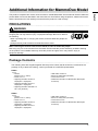
Additional Information for MammoDuo Model
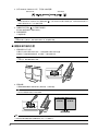
This product comprises two monitor units mounted on a dedicated stand. Some methods used to handle this
product differ from those described in the Instructions for Use. Before using the product, read this document
and the Instructions for Use carefully to ensure that the product is used correctly.
PRECAUTIONS
WARNING
Carry or place the unit according to the correct specied methods.
Dropping the unit may result in injury or equipment damage. Be sure to observe
the following.
• When unpacking and / or carrying the monitor, ensure at least two people are
utilized.
• Grasp and rmly hold the bottom and handle of the monitor.
When removing the monitor unit from the stand, be sure to utilize two people.
Removing only one of the monitors from the stand unit will make the product extremely unstable. Working
on the product in an unstable state may cause the product to topple, which may result in injury or
equipment damage.
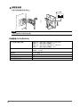
Package Contents
The following items are supplied together with the product. Check that all of them are contained in the
package. If any of these are missing, contact your dealer or local EIZO representative.
RX560
• Monitor
(Monitor unit x 2, stand)
• Power cord x 2
• Digital signal cable: PP300 x 2
DisplayPort - DisplayPort
• Digital signal cable: PP100 x 1
DisplayPort - DisplayPort
• Digital signal cable: DD300DL x 2
DVI - DVI (dual link)
• USB cable: UU300 x 2
• EIZO LCD Utility Disk (CD-ROM)
• Instructions for Use
• Additional Information for MammoDuo Model (this
document)
GX560
• Monitor
(Monitor unit x 2, stand)
• Power cord x 2
• Digital signal cable: PP300 x 4
DisplayPort - DisplayPort
• Digital signal cable: PP100 x 1
DisplayPort - DisplayPort
• USB cable: UU300 x 4
• EIZO LCD Utility Disk (CD-ROM)
• Instructions for Use
• Additional Information for MammoDuo Model (this
document)
English

2
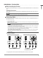
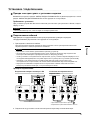
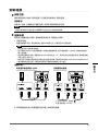
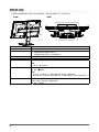
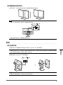
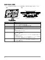
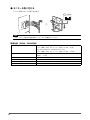
Controls and Functions
For information about the part names and functions of the monitor unit, refer to "Controls and Functions"
in the Instructions for Use.
5
6
7
8
1
4
2
3
Rear view Top view
1. Mount unit Connects the monitor unit to the stand.
2. Handle This handle is used for transportation.
3. Stand The stand enables you to:
• Adjust the position and horizontal angle of each monitor.
• Adjust the vertical / horizontal angle and height of the entire monitor
4. Cable holder Holds the monitor cables.
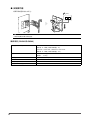
5. Rotation screw By rotating this screw, each monitor screen can be turned clockwise or
counterclockwise to adjust the size of the space between the monitors.
6. Swivel lock screw
Tightening this screw locks the horizontal angle.
Note
• The screw is not locked before shipment.
7. Tilt lock Locks the vertical angle of the monitor to 0˚.
: Locked, : Released
Note
• The angle is locked to 0˚ before shipment. To change the monitor tilt angle, release
the lock.
• When transporting the product, set the vertical angle of the monitor to 0˚ and apply
the tilt lock. This helps make transportation of the product easier.
8. Mount lock Locks the mount unit to the stand unit.
To remove the mount unit from the stand unit, release the mount lock.
: Locked, : Released

3
Installation / Connection
●
Before Installing the Product
Carefully read "PRECAUTIONS" in this document as well as "PRECAUTIONS" in the Instructions for
Use.
Installation Requirements
When installing the product, ensure that there is adequate space around the sides, back and top of
the monitor.
Attention
• Position the monitor so that there is no light to interfere with the screen.
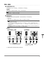
●
Connecting Cables
For information about the compatible resolutions of the monitor, refer to "Compatible Resolutions" in
the Instructions for Use.
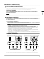
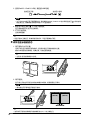
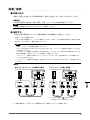
1. Connect signal cables.
Check the shapes of the connectors, and connect the cables. After connecting the DVI cable, tighten the
fasteners to secure the connector.
Attention
• Be sure to use the cables attached to the product.
• The DisplayPort connectors of the monitor consist of input and output connectors. When connecting the
monitor to a PC, connect the cable to the input connector.
• To set up a daisy-chain connection, it is necessary to set the DisplayPort version to “1.2”. For details on
how to perform setup, refer to the Installation Manual (on the CD-ROM).
• Visit the EIZO website for information about monitors and graphic boards that can be used for the daisy-
chain connection: http://www.eizoglobal.com
• Before using a daisy-chain connection, remove the cap of the output connector on the monitor that
outputs signals.
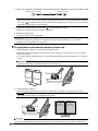
Connection examples:
Connecting each monitor to a PC Setting up a daisy-chain connection
*1, *2
*1 For the GX560, connect to
.
*2 Use attached "PP100".
2. Plug the power cord into a power outlet and the power connector on the monitor.
*1
English

4
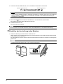
3. Connect the USB cable when using RadiCS / RadiCS LE.
Connect to monitor Connect to PC
Attention
• In order to perform monitor quality control for the GX560, connect a PC with RadiCS / RadiCS LE installed
to
. Refer to “2-2. Connecting Cables” in the Instructions for Use on how to connect cables.
4. Touch on the front of the monitor to turn on the power to the monitor.
The power switch indicator of the monitor lights up green.
5. Turn on the PC.
The screen image appears.
Note
• If the monitor does not operate correctly, refer to "No-Picture Problem" in the Instructions for Use.
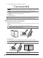
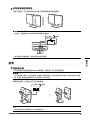
●
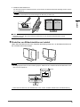
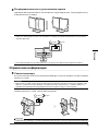
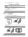
Adjusting the Posture of Each Monitor
1. Adjust the swivel and horizontal positions.
Holding the top and bottom of the monitor unit with both hands, adjust the angle and position of each monitor
individually.
The swivel angle can be locked by turning the swivel lock screw clockwise to tighten it.
Note
• The swivel lock screw is not locked before shipment.
2. Adjust the rotation.
The space between monitors can be eliminated by turning the rotation screw. Adjust as necessary.
Attention
• Do not perform rotation by moving the monitors by hand.
Note
• Use a (#2) phillips head screwdriver for the swivel lock screw and rotation screw.

5
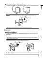
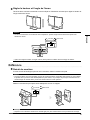
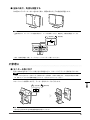
●
Adjusting the Screen Height and Angle
Holding both monitors together as in the following gure, adjust the screen height and vertical angle.
Attention
• The tilt lock is locked before shipment. Adjust the vertical angle of the screens after releasing the lock.
: Locked, : Released
• After adjusting the height and vertical angle, pass the cables through the cable holder.
Reference
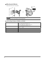
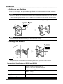
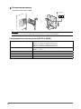
●
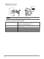
Removing the Monitor
In a case such as when you mount the optional RadiLight on the monitor, remove the monitor unit
from the stand.
Attention
• Removing only one of the monitors from the stand will make the product extremely unstable. Working on
the product in an unstable state may cause the product to topple, which may result in injury or equipment
damage. Be sure to utilize two people.
Remove the monitor unit from the stand after releasing the mount lock.
: Locked, : Released
Note
• Refer to the RadiLight Instructions for Use for information about the mounting procedure.
English

6
●
Mounting the Monitor
Mount the monitor unit on the stand.
: Locked
Attention
• Check that the mount lock indicator is in the locked position.
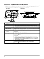
Mechanical Specications (RX560 and GX560)
Dimensions (W x H x D) 709.0 mm x 476.0 mm - 566.0 mm x 225.0 mm
(Tilt: 0°, swivel (each monitor unit) : 0°)
696.5 mm x 476.0 mm - 566.0 mm x 237.1 mm
(Tilt: 0°, swivel (each monitor unit) : 15°)
Net weight RX560: 17.3 kg
GX560: 17.1 kg
Height Adjustment 90 mm (Tilt: 0˚)
Tilt Up 25˚, down 5˚
Swivel (total) 40°
Swivel (each monitor unit) 15°

1
Zusätzliche Informationen zum MammoDuo-Modell
Dieses Produkt besteht aus zwei Monitoren, die an einem zugehörigen Standfuß montiert sind. Einige
Betriebsmethoden dieses Produkts unterscheiden sich von denen in der Gebrauchsanweisung. Lesen Sie
vor dem Gebrauch dieses Produkts dieses Dokument und die Gebrauchsanweisung sorgfältig durch, um
eine ordnungsgemäße Verwendung sicherzustellen.
VORSICHTSMASSNAHMEN
WARNUNG
Tragen oder platzieren Sie das Gerät gemäß der korrekten denierten
Methoden.
Wenn das Gerät herunterfällt, kann es zu Verletzungen oder Schäden am Gerät
kommen. Achten Sie auf Folgendes.
• Das Entpacken und / oder Transportieren des Monitors muss von mindestens
zwei Personen übernommen werden.
• Greifen Sie die Unterseite und den Griff des Monitors und halten Sie ihn fest.
Entfernen Sie den Monitor mit zwei Personen vom Standfuß.
Wenn nur ein Monitor vom Standfuß entfernt wird, ist das Produkt extrem instabil. Wenn Sie mit dem
Produkt in einem instabilen Zustand arbeiten, kann es umfallen und zu Verletzungen oder Schäden am
Gerät führen.
Verpackungsinhalt
Die folgenden Elemente werden zusammen mit dem Produkt geliefert. Prüfen Sie, ob sie alle in der
Verpackung enthalten sind. Wenn Elemente fehlen, wenden Sie sich an Ihren Fachhändler oder Ihren
EIZO-Handelsvertreter.
RX560
• Monitor
(Monitor x 2, Standfuß)
• Netzkabel x 2
• Digitales Signalkabel: PP300 x 2
DisplayPort - DisplayPort
• Digitales Signalkabel: PP100 x 1
DisplayPort - DisplayPort
• Digitales Signalkabel: DD300DL x 2
DVI - DVI (Dual-Link)
• USB-Kabel: UU300 x 2
• EIZO LCD Utility Disk (CD-ROM)
• Gebrauchsanweisung
• Zusätzliche Informationen zum MammoDuo-Modell
(dieses Dokument)
GX560
• Monitor
(Monitor x 2, Standfuß)
• Netzkabel x 2
• Digitales Signalkabel: PP300 x 4
DisplayPort - DisplayPort
• Digitales Signalkabel: PP100 x 1
DisplayPort - DisplayPort
• USB-Kabel: UU300 x 4
• EIZO LCD Utility Disk (CD-ROM)
• Gebrauchsanweisung
• Zusätzliche Informationen zum MammoDuo-Modell
(dieses Dokument)
Deutsch

2
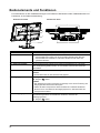
Bedienelemente und Funktionen
Für Informationen zu den Teilebezeichnungen und Funktionen des Monitors siehe „Bedienelemente und
Funktionen“ in der Gebrauchsanweisung.
5
6
7
8
1
4
2
3
Ansicht von hinten Ansicht von oben
1. Montageeinheit Verbindet den Monitor mit dem Standfuß.
2. Griff Dieser Griff wird zum Transport des Monitors genutzt.
3. Standfuß Der Standfuß ermöglicht:
• das Einstellen der Position und des horizontalen Winkels jeden Monitors.
• das Einstellen des vertikalen / horizontalen Winkels und der Höhe des
gesamten Monitors.
4. Kabelabdeckung Hält die Anschlusskabel zusammen.
5. Rotationsschraube Durch Rotieren dieser Schraube kann jeder Monitorbildschirm im oder gegen
den Uhrzeigersinn gedreht werden, um den Abstand zwischen den Monitoren
einzustellen.
6. Drehverschlussschraube
Das Festdrehen dieser Schraube befestigt den horizontalen Winkel.
Hinweis
• Die Schraube wird vor dem Versand nicht gesperrt.
7. Neigungssperre Befestigt den vertikalen Winkel des Monitors bei 0˚.
: Gesperrt, : Gelöst
Hinweis
• Der Winkel wird vor dem Versand bei 0˚ befestigt. Lösen Sie zur Änderung des
Neigungswinkels des Monitors die Sperre.
• Stellen Sie beim Transportieren dieses Produkts den vertikalen Winkel des
Monitors auf 0˚ und stellen Sie die Neigungssperre ein. Dies erleichtert den
Transport des Produkts.
8. Befestigungssperre Befestigt die Montageeinheit am Standfuß.
Um die Montageeinheit vom Standfuß zu entfernen, lösen Sie die
Befestigungssperre.
: Gesperrt, : Gelöst

3
Installation / Verbindung
●
Vor der Installation des Produkts
Lesen Sie sich sowohl die „VORSICHTSMASSNAHMEN“ dieses Dokuments als auch die
„VORSICHTSMASSNAHMEN“ in der Gebrauchsanweisung sorgfältig durch.
Hinweise zur Installation
Wenn Sie das Produkt installieren, stellen Sie sicher, dass neben, hinter und über dem Monitor
genügend Freiraum besteht.
Achtung
• Stellen Sie den Monitor nicht an einen Platz, an dem Licht direkt auf den Bildschirm fällt.
●
Anschließen von Kabeln
Für Informationen zu den kompatiblen Auösungen des Monitors siehe „Kompatible Auösungen“ in
der Gebrauchsanweisung.
1. Schließen Sie die Signalkabel an.
Überprüfen Sie die Form der Anschlüsse und schließen Sie die Kabel an. Ziehen Sie nach dem Anschließen
des DVI-Kabels den Verschluss fest, um den Steckverbinder zu sichern.
Achtung
• Verwenden Sie unbedingt die dem Produkt beiliegenden Kabel.
• Die DisplayPort-Anschlüsse des Monitors bestehen aus Eingangs- und Ausgangsanschlüssen. Zum
Anschließen des Monitors an einen PC verbinden Sie das Kabel mit dem Eingangsanschluss.
• Um eine Durchschleifverbindung einzurichten, müssen Sie die DisplayPort-Version auf „1.2“ stellen.
Informationen zum Setup nden Sie im Installationshandbuch (auf der CD-ROM).
• Informationen über Monitore und Grakkarten, die für die Durchschleifverbindung verwendet werden
können, nden Sie auf der EIZO-Website: http://www.eizoglobal.com
• Entfernen Sie vor der Verwendung einer Durchschleifverbindung die Kappe vom Ausgangsanschluss des
Monitors, der Signale ausgibt.
Beispiele für den Anschluss:
Anschließen jedes Monitors an einen PC Einrichten einer Durchschleifverbindung
*1, *2
*1 Für GX560 verbinden Sie mit
.
*2 Verwenden Sie das beiliegende „PP100“.
2. Verbinden Sie mithilfe des Netzkabels den Netzanschluss des Monitors mit einer Steckdose.
*1
Deutsch

4
3. Schließen Sie das USB-Kabel an, wenn Sie RadiCS / RadiCS LE verwenden.
Verbinden mit dem Monitor Verbinden mit dem PC
Achtung
• Um die Monitor-Qualitätskontrolle für den GX560 durchzuführen, verbinden Sie einen PC mit installiertem
RadiCS / RadiCS LE mit
. Siehe „2-2. Anschließen von Kabeln“ in der Gebrauchsanweisung zum
Anschließen von Kabeln.
4. Berühren Sie auf der Vorderseite des Monitors, um den Monitor einzuschalten.
Die Netzkontrollschalter-LED des Monitors leuchtet grün.
5. Schalten Sie den PC ein.
Das Schirmbild wird angezeigt.
Hinweis
• Wenn der Monitor nicht korrekt funktioniert, siehe „Keine-Bildprobleme“ in der Gebrauchsanweisung.
●
Einstellen der Ausrichtung jedes Monitors
1. Stellen Sie Drehung und horizontalen Positionen ein.
Halten Sie Ober- und Unterseite jedes Monitors mit beiden Händen fest und stellen Sie den Winkel und die
Position jedes Monitors einzeln ein.
Der Drehwinkel kann gesperrt werden, indem die Drehverschlussschraube zum Anziehen im Uhrzeigersinn
gedreht wird.
Hinweis
• Die Drehverschlussschraube wird vor dem Versand nicht gesperrt.

5
2. Stellen Sie die Rotation ein.
Der Abstand zwischen den Monitoren kann durch Drehen der Rotationsschraube beseitigt werden. Passen
Sie nach Bedarf an.
Achtung
• Führen Sie die Rotation nicht durch Bewegen der Monitore per Hand aus.
Hinweis
• Verwenden Sie einen (#2) Kreuzschlitzschraubenzieher für die Drehverschlussschraube und die
Rotationsschraube.
●
Einstellen von Bildschirmhöhe und -winkel
Halten Sie beide Monitore wie in der folgenden Darstellung zusammen, um die Bildschirmhöhe und
den vertikalen Winkel einzustellen.
Achtung
• Die Neigungssperre wird vor dem Versand gesperrt. Stellen Sie den vertikalen Winkel der Bildschirme nach
dem Lösen der Sperre ein.
: Gesperrt, : Gelöst
• Führen Sie die Kabel nach dem Einstellen der Höhe und des vertikalen Winkels durch die Kabelhalterung.
Deutsch

6
Referenz
●
Entfernen des Monitors
Wenn Sie, zum Beispiel, die optionale RadiLight-Einheit am Monitor montieren möchten, entfernen
Sie den Monitor vom Standfuß.
Achtung
• Wenn nur ein Monitor vom Standfuß entfernt wird, ist das Produkt extrem instabil. Wenn Sie mit dem Produkt
in einem instabilen Zustand arbeiten, kann es umfallen und zu Verletzungen oder Schäden am Gerät führen.
Führen Sie den Vorgang mit zwei Personen durch.
Entfernen Sie den Monitor vom Standfuß, nachdem Sie die Befestigungssperre gelöst haben.
: Gesperrt, : Gelöst
Hinweis
• Siehe die RadiLight-Gebrauchsanweisung für Informationen zur Montage.
●
Montage des Monitors
Montieren Sie den Monitor auf dem Standfuß.
: Gesperrt
Achtung
• Überprüfen Sie, ob sich der Indikator der Befestigungssperre in der gesperrten Position bendet.
Mechanische Spezikationen (RX560 und GX560)
Abmessungen (B x H x T) 709,0 mm x 476,0 mm - 566,0 mm x 225,0 mm
(Neigung: 0°, Drehung (jeder Monitor): 0°)
696,5 mm x 476,0 mm - 566,0 mm x 237,1 mm
(Neigung: 0°, Drehung (jeder Monitor): 15°)
Nettogewicht RX560: 17,3 kg
GX560: 17,1 kg
Höhenanpassung 90 mm (Neigung: 0˚)
Neigung Nach oben 25˚, nach unten 5˚
Drehung (vollständig) 40°
Drehung (jeder Monitor) 15°

1
Informations supplémentaires pour le modèle MammoDuo
Ce produit inclut deux moniteurs montés sur un pied spécial. Certaines méthodes de manipulation de ce
produit diffèrent de celles décrites dans la Notice d’instruction. Avant d’utiliser le produit, lisez attentivement
ce document ainsi que la Notice d’instruction an d’assurer une utilisation correcte du produit.
PRECAUTIONS
AVERTISSEMENT
Transportez ou placez l’appareil conformément aux méthodes spéciées.
Vous pourriez vous blesser ou endommager le matériel en laissant tomber
l’appareil. Veillez à respecter les points suivants.
• Lors du déballage et/ou du transport du moniteur, assurez-vous qu'au moins
deux personnes sont présentes.
• Empoignez fermement le bas et la poignée du moniteur.
Lorsque vous retirez le moniteur du pied, veillez à ce que cette opération soit effectuée par deux
personnes.
Si vous ne retirez qu’un seul moniteur du pied, le produit sera dans un équilibre très précaire. Si vous
utilisez le produit alors qu'il est en état de déséquilibre, il peut tomber, ce qui risque de provoquer des
blessures ou d’endommager le matériel.
Contenu de l’emballage
Les articles suivants sont fournis avec le produit. Vériez qu’ils sont tous inclus dans l’emballage. Si le
moindre de ces articles manque, contactez votre revendeur ou votre représentant EIZO local.
RX560
• Moniteur
(moniteur x 2, pied)
• Cordon d’alimentation x 2
• Câble de signal digital : PP300 x 2
DisplayPort - DisplayPort
• Câble de signal digital : PP100 x 1
DisplayPort - DisplayPort
• Câble de signal digital : DD300DL x 2
DVI - DVI (dual link)
• Câble USB : UU300 x 2
• EIZO LCD Utility Disk (CD-ROM)
• Notice d’instruction
• Informations supplémentaires pour le modèle
MammoDuo (ce document)
GX560
• Moniteur
(moniteur x 2, pied)
• Cordon d’alimentation x 2
• Câble de signal digital : PP300 x 4
DisplayPort - DisplayPort
• Câble de signal digital : PP100 x 1
DisplayPort - DisplayPort
• Câble USB : UU300 x 4
• EIZO LCD Utility Disk (CD-ROM)
• Notice d’instruction
• Informations supplémentaires pour le modèle
MammoDuo (ce document)
Français

2
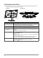
Commandes et fonctions
Pour obtenir des informations sur les noms des pièces et les fonctions du moniteur, reportez-vous à
« Commandes et fonctions » dans la Notice d’instruction.
5
6
7
8
1
4
2
3
Vue arrière Vue du dessus
1. Support Relie le moniteur au pied.
2. Poignée Cette poignée est utilisée pour le transport.
3. Pied Le pied vous permet de :
• Régler la position et l’angle horizontal de chaque moniteur.
• Régler l’angle vertical / horizontal et la hauteur du moniteur entier
4. Enveloppe de câbles Maintient les câbles du moniteur.
5. Vis de rotation Lorsque vous tournez cette vis, vous pouvez tourner chaque écran de moniteur dans
le sens horaire ou antihoraire pour régler la taille de l’espace entre les moniteurs.
6. Vis de verrouillage de
pivotement
Serrer cette vis verrouille l’angle horizontal.
Remarque
• La vis n’est pas bloquée avant l’expédition.
7. Verrou d'inclinaison Verrouille l’angle vertical du moniteur sur 0˚.
: verrouillé, : déverrouillé
Remarque
• L’angle est verrouillé sur 0˚ avant l’expédition. Pour changer l’angle d'inclinaison du
moniteur, débloquez le verrou.
• Lorsque vous transportez le produit, réglez l’angle vertical du moniteur sur 0˚ et
enclenchez le verrou d’inclinaison. Cela facilite le transport du produit.
8. Verrou du support Verrouille le support au pied.
Pour retirer le support du pied, débloquez le verrou du support.
: verrouillé, : déverrouillé

3
Installation / Connexion
●
Avant l’installation du produit
Lisez attentivement la section « PRECAUTIONS » de ce document ainsi que la section
« PRECAUTIONS » de la Notice d’instruction.
Conditions d’installation
Lors de l’installation du produit, veillez à laisser un espace sufsant à l’arrière, au-dessus et sur les
côtés du moniteur.
Attention
• Positionnez le moniteur de manière à éviter tout reet lumineux sur l’écran.
●
Câbles de raccordement
Pour obtenir plus d’informations sur les résolutions compatibles du moniteur, reportez-vous à la
section « Résolutions compatibles » dans la Notice d’instruction.
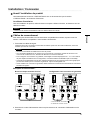
1. Raccorder les câbles de signal.
Vériez la forme des connecteurs et branchez les câbles. Après avoir raccordé le câble DVI, serrez les
attaches pour xer le connecteur.
Attention
• Assurez-vous d’utiliser les câbles fournis avec le produit.
• Les connecteurs DisplayPort du moniteur sont composés de connecteurs d’entrée et de sortie. Pour
connecter le moniteur à un PC, branchez le câble sur le connecteur d’entrée.
• Pour congurer une connexion en guirlande, il faut régler la version DisplayPort sur « 1.2 ». Pour obtenir
de plus amples informations sur la conguration, consultez le Manuel d’installation (sur le CD-ROM).
• Consultez le site Web EIZO pour de plus amples informations sur les moniteurs et les cartes graphiques
pouvant être utilisés pour la connexion en guirlande : http://www.eizoglobal.com
• Avant d'utiliser une connexion en guirlande, retirez l’embout du connecteur de sortie situé sur le moniteur
émettant les signaux.
Exemples de branchement :
Brancher chaque moniteur à un PC Conguration d'une connexion en guirlande
*1, *2
*1 Pour le GX560, connectez à
.
*2 Utilisez le « PP100 » fourni.
2. Branchez le cordon d’alimentation dans une prise secteur et le connecteur d’alimentation sur le
moniteur.
*1
Français

4
3. Connectez le câble USB si vous utilisez RadiCS / RadiCS LE.
Raccordez au moniteur Raccordez au PC
Attention
• Pour effectuer le contrôle de la qualité du moniteur du GX560, connectez un PC équipé de RadiCS /
RadiCS LE à
. Reportez-vous à « 2-2. Câbles de raccordement» dans la Notice d’instruction sur le
raccordement des câbles.
4. Appuyez sur à l’avant du moniteur pour mettre le moniteur sous tension.
L’indicateur d’alimentation du moniteur s’allume en vert.
5. Mettez en marche le PC.
L'image d'écran apparaît.
Remarque
• Si le moniteur ne fonctionne pas correctement, reportez-vous à « Problème « Pas d’image » » dans la Notice
d’instruction.
●
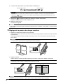
Réglage de la posture de chaque moniteur
1. Réglez les positions de pivotement et horizontale.
Tenez le haut et le bas du moniteur avec les deux mains pour régler l'angle et la position de chaque moniteur
individuellement.
L'angle de pivotement peut être verrouillé en tournant la vis du verrou de pivotement dans le sens horaire
pour la serrer.
Remarque
• La vis du verrou de pivotement n'est pas bloquée avant l'expédition.
2. Réglez la rotation.
L’espace entre les moniteurs peut être supprimé en tournant la vis de rotation. Réglez si nécessaire.
Attention
• N'effectuez aucune rotation en déplaçant les moniteurs à la main.
Remarque
• Utilisez un tournevis cruciforme n° 2 pour la vis du verrou de pivotement et la vis de rotation.

5
●
Régler la hauteur et l'angle de l'écran
Tenez les deux moniteurs ensemble comme indiqué sur l’illustration suivante pour régler la hauteur et
l’angle vertical de l’écran.
Attention
• Le verrou d’inclinaison est enclenché avant l’expédition. Ajustez l'angle vertical des écrans après avoir
desserré le verrou.
: verrouillé, : déverrouillé
• Après avoir réglé la hauteur et l'angle vertical, faites passer les câbles dans l’enveloppe de câbles.
Référence
●
Retrait du moniteur
Si vous montez le RadiLight optionnel sur le moniteur, retirez le moniteur du pied.
Attention
• Si vous ne retirez qu’un seul moniteur du pied, le produit sera dans un équilibre très précaire. Si vous utilisez
le produit alors qu'il est en état de déséquilibre, il peut tomber, ce qui risque de provoquer des blessures ou
d’endommager le matériel. Deux personnes doivent effectuer cette opération.
Retirez le moniteur du pied après avoir débloqué le verrou du support.
: verrouillé, : déverrouillé
Remarque
• Reportez-vous à la Notice d’instruction du RadiLight pour plus d’informations sur la procédure de montage.
Français

6
●
Montage du moniteur
Montez le moniteur sur le pied.
: verrouillé
Attention
• Vériez que l'indicateur de verrouillage du support est en position verrouillée.
Spécications mécaniques (RX560 et GX560)
Dimensions (L x H x P) 709 mm x 476 mm - 566 mm x 225 mm
(Inclinaison : 0°, pivotement (chaque moniteur) : 0°)
696,5 mm x 476 mm - 566 mm x 237,1 mm
(Inclinaison : 0°, pivotement (chaque moniteur) : 15°)
Poids net RX560 : 17,3 kg
GX560 : 17,1 kg
Hauteur réglable 90 mm (Inclinaison : 0˚)
Inclinaison Vers le haut : 25˚, vers le bas : 5˚
Pivotement (total) 40°
Pivotement (chaque moniteur) 15°
La page est en cours de chargement...
La page est en cours de chargement...
La page est en cours de chargement...
La page est en cours de chargement...
La page est en cours de chargement...
La page est en cours de chargement...
La page est en cours de chargement...
La page est en cours de chargement...
La page est en cours de chargement...
La page est en cours de chargement...
La page est en cours de chargement...
La page est en cours de chargement...
La page est en cours de chargement...
La page est en cours de chargement...
La page est en cours de chargement...
La page est en cours de chargement...
La page est en cours de chargement...
La page est en cours de chargement...
La page est en cours de chargement...
La page est en cours de chargement...
La page est en cours de chargement...
La page est en cours de chargement...
La page est en cours de chargement...
La page est en cours de chargement...
La page est en cours de chargement...
La page est en cours de chargement...
La page est en cours de chargement...
La page est en cours de chargement...
-
 1
1
-
 2
2
-
 3
3
-
 4
4
-
 5
5
-
 6
6
-
 7
7
-
 8
8
-
 9
9
-
 10
10
-
 11
11
-
 12
12
-
 13
13
-
 14
14
-
 15
15
-
 16
16
-
 17
17
-
 18
18
-
 19
19
-
 20
20
-
 21
21
-
 22
22
-
 23
23
-
 24
24
-
 25
25
-
 26
26
-
 27
27
-
 28
28
-
 29
29
-
 30
30
-
 31
31
-
 32
32
-
 33
33
-
 34
34
-
 35
35
-
 36
36
-
 37
37
-
 38
38
-
 39
39
-
 40
40
-
 41
41
-
 42
42
-
 43
43
-
 44
44
-
 45
45
-
 46
46
-
 47
47
-
 48
48


Eizo RX560 Le manuel du propriétaire
- Taper
- Le manuel du propriétaire
- Ce manuel convient également à
dans d''autres langues
- Deutsch: Eizo RX560 Bedienungsanleitung
- 日本語: Eizo RX560 取扱説明書
Documents connexes
-
Eizo GX340 Le manuel du propriétaire
-
 Radiforce RX440 Le manuel du propriétaire
-
-
-
-
Eizo MX215 Le manuel du propriétaire
-
-
-
-
