Bosch GST18V-50N Manuel utilisateur
- Catégorie
- Outils électroportatifs
- Taper
- Manuel utilisateur

For English Version
See page 2
Version française
Voir page 19
Versión en español
Ver la página 35
IMPORTANT
Read Before Using
IMPORTANT
Lire avant usage
IMPORTANTE
Leer antes de usar
Operating / Safety Instructions
Consignes d’utilisation / de sécurité
Instrucciones de funcionamiento y seguridad
Call Toll Free for Consumer Information & Service Locations
Pour obtenir des informations et les adresses de nos centres de service après-vente, appelez ce numéro gratuit
Llame gratis para obtener información para el consumidor y ubicaciones de servicio
1-877-BOSCH99 (1-877-267-2499) www.boschtools.com
GST18V-50
160992A7EF_GST18V50_202203.indd 1 3/25/22 11:47 AM

-2-
General Power Tool Safety Warnings
Read all safety warnings, instructions, illustrations and specifications provid-
ed with this power tool. Failure to follow all instructions listed below may result
in electric shock, fire and/or serious injury.
SAVE ALL WARNINGS AND INSTRUCTIONS FOR FUTURE REFERENCE
The term “power tool” in the warnings refers to your mains-operated (corded) power tool or
battery-operated (cordless) power tool.
1. Work area safety
a. Keep work area clean and well lit. Cluttered
or dark areas invite accidents.
b. Do not operate power tools in explosive
atmospheres, such as in the presence of
flammable liquids, gases or dust. Power
tools create sparks which may ignite the dust
or fumes.
c. Keep children and bystanders away while
operating a power tool. Distractions can
cause you to lose control.
2. Electrical safety
a. Power tool plugs must match the outlet.
Never modify the plug in any way. Do not use
any adapter plugs with earthed (grounded)
power tools. Unmodified plugs and matching
outlets will reduce risk of electric shock.
b. Avoid body contact with earthed or ground-
ed surfaces, such as pipes, radiators, rang-
es and refrigerators. There is an increased
risk of electric shock if your body is earthed
or grounded.
c. Do not expose power tools to rain or wet
conditions. Water entering a power tool will
increase the risk of electric shock.
d. Do not abuse the cord. Never use the cord
for carrying, pulling or unplugging the power
tool. Keep cord away from heat, oil, sharp
edges or moving parts. Damaged or entan-
gled cords increase the risk of electric shock.
e. When operating a power tool outdoors, use
an extension cord suitable for outdoor use.
Use of a cord suitable for outdoor use reduc-
es the risk of electric shock.
f. If operating a power tool in a damp location
is unavoidable, use a Ground Fault Circuit
Interrupter (GFCI) protected supply. Use of
an GFCI reduces the risk of electric shock.
3. Personal safety
a. Stay alert, watch what you are doing and
use common sense when operating a power
tool. Do not use a power tool while you are
tired or under the influence of drugs, alco-
hol or medication. A moment of inattention
while operating power tools may result in se-
rious personal injury.
b. Use personal protective equipment. Always
wear eye protection. Protective equipment
such as a dust mask, non-skid safety shoes,
hard hat, or hearing protection used for ap-
propriate conditions will reduce personal
injuries.
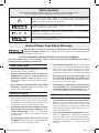
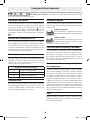
Safety Symbols
The definitions below describe the level of severity for each signal word.
Please read the manual and pay attention to these symbols.
!
This is the safety alert symbol. It is used to alert you to potential
personal injury hazards. Obey all safety messages that follow this
symbol to avoid possible injury or death.
DANGER indicates a hazardous situation which, if not avoided, will
result in death or serious injury.
WARNING indicates a hazardous situation which, if not avoided,
could result in death or serious injury.
CAUTION indicates a hazardous situation which, if not avoided, could
result in minor or moderate injury.
160992A7EF_GST18V50_202203.indd 2 3/25/22 11:47 AM

-3-
General Power Tool Safety Warnings
c. Prevent unintentional starting. Ensure the
switch is in the off-position before connect-
ing to power source and / or battery pack,
picking up or carrying the tool. Carrying
power tools with your finger on the switch or
energizing power tools that have the switch
on invites accidents.
d. Remove any adjusting key or wrench before
turning the power tool on. A wrench or a key
left attached to a rotating part of the power
tool may result in personal injury.
e. Do not overreach. Keep proper footing and
balance at all times. This enables better con-
trol of the power tool in unexpected situa-
tions.
f. Dress properly. Do not wear loose clothing
or jewelry. Keep your hair and clothing away
from moving parts. Loose clothes, jewelry or
long hair can be caught in moving parts.
g. If devices are provided for the connection
of dust extraction and collection facilities,
ensure these are connected and properly
used. Use of dust collection can reduce
dust-related hazards.
h. Do not let familiarity gained from frequent
use of tools allow you to become compla-
cent and ignore tool safety principles. A
careless action can cause severe injury with-
in a fraction of a second.
4. Power tool use and care
a. Do not force the power tool. Use the correct
power tool for your application. The correct
power tool will do the job better and safer at
the rate for which it was designed.
b. Do not use the power tool if the switch
does not turn it on and off. Any power tool
that cannot be controlled with the switch is
dangerous and must be repaired.
c. Disconnect the plug from the power source
and/or remove the battery pack, if detach-
able, from the power tool before making
any adjustments, changing accessories, or
storing power tools. Such preventive safe-
ty measures reduce the risk of starting the
power tool accidentally.
d. Store idle power tools out of the reach of
children and do not allow persons unfamil-
iar with the power tool or these instructions
to operate the power tool. Power tools are
dangerous in the hands of untrained users.
e. Maintain power tools and accessories.
Check for misalignment or binding of mov-
ing parts, breakage of parts and any other
condition that may affect the power tool’s
operation. If damaged, have the power tool
repaired before use. Many accidents are
caused by poorly maintained power tools.
f. Keep cutting tools sharp and clean. Prop-
erly maintained cutting tools with sharp
cutting edges are less likely to bind and are
easier to control.
g. Use the power tool, accessories and tool
bits etc. in accordance with these instruc-
tions, taking into account the working condi-
tions and the work to be performed. Use of
the power tool for operations different from
those intended could result in a hazardous
situation.
h. Keep handles and grasping surfaces dry,
clean and free from oil and grease. Slippery
handles and grasping surfaces do not allow
for safe handling and control of the tool in
unexpected situations.
5. Battery tool use and care
a. Recharge only with the charger specified
by the manufacturer. A charger that is suit-
able for one type of battery pack may create
a risk of fire when used with another battery
pack.
b. Use power tools only with specifically des-
ignated battery packs. Use of any other bat-
tery packs may create a risk of injury and fire.
c. When battery pack is not in use, keep it
away from other metal objects like paper
clips, coins, keys, nails, screws, or other
small metal objects that can make a con-
nection from one terminal to another.
Shorting the battery terminals together may
cause burns or a fire.
d. Under abusive conditions, liquid may be
ejected from the battery; avoid contact. If
contact accidentally occurs, flush with wa-
ter. If liquid contacts eyes, additionally seek
medical help. Liquid ejected from the bat-
tery may cause irritation or burns.
e. Do not use a battery pack or tool that is
damaged or modified. Damaged or modified
batteries may exhibit unpredictable behavior
resulting in fire, explosion or risk of injury.
160992A7EF_GST18V50_202203.indd 3 3/25/22 11:47 AM

-4-
General Power Tool Safety Warnings
f. Do not expose a battery pack or tool to fire
or excessive temperature. Exposure to fire
or temperature above 265 °F may cause ex-
plosion.
g. Follow all charging instructions and do not
charge the battery pack or tool outside the
temperature range specified in the instruc-
tions. Charging improperly or at tempera-
tures outside the specified range may dam-
age the battery and increase the risk of fire.
6. Service
a. Have your power tool serviced by a quali-
fied repair person using only identical re-
placement parts. This will ensure that the
safety of the power tool is maintained.
b. Never service damaged battery packs. Ser-
vice of battery packs should only be per-
formed by the manufacturer or authorized
service providers.
a. Hold the power tool by insulated gripping
surfaces, when performing an operation
where the cutting accessory may contact
hidden wiring. Cutting accessory contacting
a “live” wire may make exposed metal parts
of the power tool “live” and could give the
operator an electric shock.
b. Use clamps or another practical way to se-
cure and support the workpiece to a stable
platform. Holding the workpiece by hand or
against your body leaves it unstable and may
lead to loss of control.
c. Do not drill, fasten or break into existing
walls or other blind areas where electrical
wiring may exist. If this situation is unavoid-
able, disconnect all fuses or circuit breakers
feeding this worksite.
d. Disconnect battery pack from tool or place
the switch in the locked or off position be-
fore making any assembly, adjustments or
changing accessories. Such preventive safe-
ty measures reduce the risk of starting the
tool accidentally.
e. Never leave the trigger locked “ON”. Before
inserting the battery pack, check that the
trigger lock is “OFF”. Accidental start-ups
could cause injury.
f. Keep hands away from cutting area. Do
not reach under the material being cut. The
proximity of the blade to your hand is hidden
from your sight.
g. Keep hands from between the gear hous-
ing and saw blade holder. The reciprocating
blade holder can pinch your fingers.
h. Do not use dull or damaged blades. Bent
blade can break easily or cause kickback.
i. Before starting to cut, turn tool “ON” and
allow the blade to come to full speed. Tool
can chatter or vibrate if blade speed is too
slow at beginning of cut and possibly kick-
back.
j. Secure material before cutting. Never hold
it in your hand or across legs. Small or thin
material may flex or vibrate with the blade,
causing loss of control.
k. Make certain all adjusting screws and the
blade holder are tight before making a cut.
Loose adjusting screws and holders can
cause the tool or blade to slip and loss of
control may result.
l. When removing the blade from the tool
avoid contact with skin and use proper
protective gloves when grasping the blade
or accessory. Accessories may be hot after
prolonged use.
Safety Rules for Cordless Jig Saws
160992A7EF_GST18V50_202203.indd 4 3/25/22 11:47 AM

-5-
Additional Safety Warnings
GFCI and personal protection devices like elec-
trician’s rubber gloves and footwear will further
enhance your personal safety.
Develop a periodic maintenance schedule for
your tool. When cleaning a tool be careful not
to disassemble any portion of the tool since
internal wires may be misplaced or pinched or
safety guard return springs may be improperly
mounted. Certain cleaning agents such as gaso-
line, carbon tetrachloride, ammonia, etc. may
damage plastic parts.
Ensure the switch is in the off position before
inserting battery pack. Inserting the battery
pack into power tools that have the switch on
invites accidents.
Some dust created by power
sanding, sawing, grinding,
drilling, and other construction activities con-
tains chemicals known to cause cancer, birth
defects or other reproductive harm. Some ex-
amples of these chemicals are:
• Leadfromlead-basedpaints,
• Crystalline silica from bricks and cement
and other masonry products, and
• Arsenic and chromium from chemically-
treated lumber.
Your risk from these exposures varies, depend-
ing on how often you do this type of work. To
reduce your exposure to these chemicals: work
in a well ventilated area, and work with ap-
proved safety equipment, such as those dust
masks that are specially designed to filter out
microscopic particles.
160992A7EF_GST18V50_202203.indd 5 3/25/22 11:47 AM

-6-
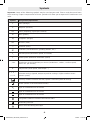
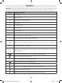
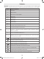
Symbols
Important: Some of the following symbols may be used on your tool. Please study them and learn
their meaning. Proper interpretation of these symbols will allow you to operate the tool better and
safer.
Symbol Designation/Explanation
V Volts (voltage)
A Amperes (current)
Hz Hertz (frequency, cycles per second)
W Watt (power)
kg Kilograms (weight)
min Minutes (time)
s Seconds (time)
⌀Diameter (size of drill bits, grinding wheels, etc.)
n0No load speed (rotational speed, at no load)
n Rated speed (Maximum attainable speed)
.../min Revolutions or reciprocation per minute (revolutions, strokes, surface speed,
orbits etc. per minute)
0 Off position (zero speed, zero torque...)
1, 2, 3, ...
I, II, III,
Selector settings (speed, torque or position settings. Higher number means
greater speed)
Infinitely variable selector with off (speed is increasing from 0 setting)
Arrow (action in the direction of arrow)
Type or a characteristic of current
Type or a characteristic of current
Type or a characteristic of current
Designates Double Insulated Construction tools
Grounding terminal
Alerts user to warning messages
160992A7EF_GST18V50_202203.indd 6 3/25/22 11:47 AM

-7-
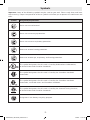
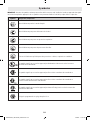
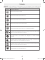
Symbols
Important: Some of the following symbols may be used on your tool. Please study them and learn
their meaning. Proper interpretation of these symbols will allow you to operate the tool better and
safer.
Symbol Designation/Explanation
Alerts user to read manual.
Alerts user to wear eye protection.
Alerts user to wear respiratory protection.
Alerts user to wear hearing protection.
Alerts user to wear eye, respiratory, and hearing protection.
This symbol designates that this tool is listed by Underwriters Laboratories,
to United States and Canadian Standards.
This symbol designates that this tool is listed by the Canadian Standards
Association.
This symbol designates that this tool is listed by the Canadian Standards
Association, to United States and Canadian Standards.
This symbol designates that this tool is listed by the Intertek Testing Services,
to United States and Canadian Standards.
Designates Li-ion battery recycling program.
160992A7EF_GST18V50_202203.indd 7 3/25/22 11:47 AM

-8-
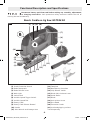
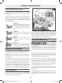
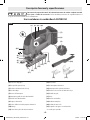
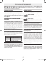
Functional Description and Specifications
(20)
(5) (6)
(7)
(8)
(9)
(11)
(12)
(13)
(14)
(15)
(16)
(17)
(1)
(2)
(3)
(4)
(21)
(10)
(18) (19)
(21)
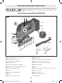
(1) Shock Protection Guard
(2) Blade Receptacle
(3) Blade Release Lever
(4) Work Light
(5) Switch Lock
(6) Variable Speed Trigger Switch
(7) Variable Speed Dial
(8) Battery Pack*
(9) Battery Pack Release Button*
(10) Handle
(11) Allen Wrench and Storage Area
(12) Footplate
(13) Non-Marring Overshoe
(14) Chip Blower Switch
(15) Blade Orbit Selector Lever
(16) Guide Roller
(17) Blade
(18) Anti-Splinter Insert
(19) Dust Hood
(20) Extraction Outlet
(21) Insulated gripping surface
* Sold Separately
Disconnect battery pack from tool before making any assembly, adjustments
or changing accessories. Such preventive safety measures reduce the risk of
starting the tool accidentally.
Bosch Cordless Jig Saw GST18V-50
Fig. 1
160992A7EF_GST18V50_202203.indd 8 3/25/22 11:47 AM

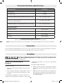
-9-
Battery Packs / Chargers:
Please refer to the battery/charger list, included with your tool.
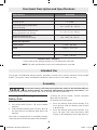
NOTE: For tool specifications refer to the nameplate on your tool.
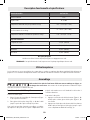
Model Number GST18V-50
Voltage rating 18 V
No load speed 0–3,500
Permitted battery temperature
during charging +32…+113°F (0…+45°C)
Permitted ambient temperature
during operation and storage -4…+122°F (-20…+50°C)
Recommended ambient
temperature during charging +32…+95°F (0...+35°C)
Maximum Capacities
Stroke length 1-1/32” (26 mm)
Wood 4-59/64” (125 mm)
Aluminum 25/32” (20 mm)
Mild steel 25/64” (10 mm)
Functional Description and Specifications
Assembly
Disconnect battery pack from tool or place the switch in the locked or off posi-
tion before making any assembly, adjustments or changing accessories. Such
preventive safety measures reduce the risk of starting the tool accidentally.
Inserting and Releasing
Battery Pack
To insert the battery pack:
1. Set switch lock (Figure 1, 5) to the locked
position.
2. Slide charged battery pack (Figure 1, 8) into
the housing until the battery pack locks into
position.
Your tool is equipped with a secondary locking
latch to prevent the battery pack from complete-
ly falling out of the handle, should it become
loose due to vibration.
To remove the battery pack:
1. Press the battery pack release button (Fig-
ure 1, 9) and slide the battery pack (Figure
1, 8) forward.
2. Press the battery pack release button (Fig-
ure 1, 9) again and slide the battery pack
(Figure 1, 8) completely out of tool housing.
The jigsaw is intended for making straight, curved or intricate cuts in various materials using suitable
blades. The jigsaw is only intended for handheld, supervised use. For indoor use only.
Intended Use
160992A7EF_GST18V50_202203.indd 9 3/25/22 11:47 AM

-10-
Assembly
(3)
(2)(16)
(17)
Fig. 2
(17)
(3)
Fig. 3
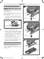
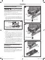
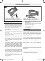
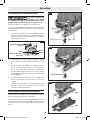
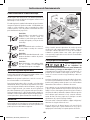
Blade Installation And Removal
This jigsaw is equipped with
a Bosch tool-less blade
changing system for fast and easy changes of
T-shank blades. (Note: This jigsaw does not ac-
cept U-shank blades.)
If blade is not properly installed, then the blade
may unexpectedly dislodge from jigsaw when
tool is energized.
1. Pull the blade release lever (3) to the point
that the slots on the blade clamp’s ring line
up with the slot in the center of the clamp
(Fig. 2 & 3).
Blade Release Lever
Slot
Blade Clamp Ring
Slot
Slot
2. To remove a previously-used blade, simply
pull it out of the blade clamp (Fig. 4).
3. Insert the saw blade (17) (teeth in cutting
direction) until it the “T” part of the blade
shank is completely inserted in to the blade
clamp (2). When inserting the saw blade, the
back of the blade must rest in the groove of
the guide roller (16) (Fig. 3).
4. When blade release lever (3) is released, it
will spring back to its closed position.
5. Verify that the blade clamp (2) has also re-
turned to its closed position (which is the
point where slots were previously).
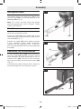
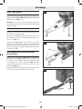
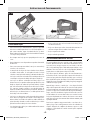
Attaching Non-Marring Overshoe
Your tool is equipped with a protective plastic
overshoe that protects finer surfaces.
To attach, hook overshoe (13) over front of met-
al footplate (12) and snap into place at rear of
footplate (Fig. 5).
(12)
(13)
Fig. 4
Fig. 5
160992A7EF_GST18V50_202203.indd 10 3/25/22 11:47 AM

-11-
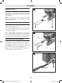
Assembly
(12)(18)
Fig. 6
Anti-Splinter Insert
To minimize splintering of the top surface of
the material being cut, place the JA1013 anti-
splinter insert (18) in the blade opening of the
footplate (12) (Fig. 6).
Note: This insert will only work with blades
that have ground sides such as T301CD, T101B,
T101D, and T101DP.
Dust Cover
Fit the hood before you connect the power tool
to the dust extraction system.
Attach the hood (19) to the power tool so that
the bracket locks into place on the shock protec-
tion guard (1) (Fig. 7).
Remove the hood (19) when working without
a dust extraction system, blade installation/
removal, and for miter/bevel cuts. To do this,
pull the hood forwards off the shock protection
guard (1).
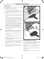
Connecting The Dust Extraction
Fit the extraction outlet (20) in the recesses of
the base plate (12). Rotate the Allen wrench
head clockwise to allow connection of the ex-
traction outlet (20). Connect a dust extraction
hose (not included) to the extraction outlet (20)
(Fig. 8).
Switch off the sawdust blower device when you
have connected the dust extraction system.
(1)
(19)
Fig. 7
(20) (12)
Fig. 8
160992A7EF_GST18V50_202203.indd 11 3/25/22 11:47 AM

-12-
Operating Instructions
Disconnect battery pack from tool or place the switch in the locked or off posi-
tion before making any assembly, adjustments or changing accessories. Such
preventive safety measures reduce the risk of starting the tool accidentally.
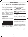
Switch Lock
The switch lock (5) is designed to prevent ac-
cidental starts. To operate switch, press the
switch lock button with your thumb to the un-
lock symbol . To lock the switch, press the
switch lock button to the lock symbol (Fig. 1).
Variable Speed Trigger Switch
Your tool is equipped with a variable speed trig-
ger switch (6). The tool can be turned “ON”
or “OFF” by squeezing or releasing the trigger.
The speed can be adjusted from the minimum
to maximum nameplate SPM by the pressure
you apply to the trigger. Apply more pressure to
increase the speed and release pressure to de-
crease speed (Fig. 1).
Variable Speed Dial
Your jig saw is equipped with a variable speed
dial (7). The blade stroke rate may be adjusted
during cutting operation by presetting the dial on
or between any one of the six numbers (Fig. 1).
Stroke settings
1–2 Low stroke rate
3–4 Medium stroke rate
5–6 High stroke rate
Work Light
Your tool is equipped with a work light (4) for
better visibility during operation. When the tool
is turned on, the light turns on. When the tool
is turned off, there is a slight delay before the
light turns off.
Chip Blower
Your jig saw is equipped with a chip blower to
help keep the cutting line clear of chips.
Blower switched on
For working with wood, plastic and
similar material that produce large
amounts of sawdust.
Blower switched off
For working with metals and when
cooling agents are used, or with dust
collection accessory.
Protection Against Deep
Discharging
The lithium ion battery is protected against deep
discharging by the “Electronic Cell Protection
(ECP)”. When the battery is empty, the tool is
switched off by means of a protective circuit.
Temperature-dependent
Overload Protection
In normal conditions of use, the tool cannot be
overloaded. However, if the power tool is over-
loaded or not kept within the permitted battery
temperature range, the speed is reduced or the
power tool switches off.
If the tool speed is automatically reduced in
such situations, the tool will run again at full
speed once the permitted battery temperature
is reached or the load is reduced. During auto-
matic shut-down, switch off the power tool, al-
low the battery to cool down, and then switch
the power tool back on (Fig. 1).
Brake
When the trigger is released it activates the
electrical brake to stop the blade quickly. This
feature is especially useful when making repeti-
tive cuts.
160992A7EF_GST18V50_202203.indd 12 3/25/22 11:47 AM

-13-
Operating Instructions
Blade Orbit Selector Lever
Maximum cutting efficiency can be obtained by
adjusting the blade orbit selector lever to suit
the material being cut.
The following chart will help you determine
which setting to use for your application. This
chart is intended as a guideline only, and test
cuts in scrap material should be performed first
to determine the best setting.
Setting 0
Hard materials such as metals or
thin sheet metals. This setting
can be used with knife blades,
grit edge blades, rasp work. and
down cutting blades.
Setting 1
Soft materials where cleaner
cutting or delicate scrolling work
is performed.
Setting 2
Medium density materials such
as harder woods or particle
board.
Setting 3
Soft materials such as wood,
plastics, etc. and when fast cut-
ting is more important than a
clean cut.
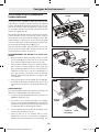
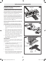
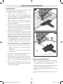
Footplate Angle Adjustment
The footplate may be tilted to allow angle cuts
up to 45° in either direction.
Note: Before adjusting the footplate, remove
anti-splinter insert, if used.
To adjust footplate, loosen screw with allen
wrench (11) provided, slide the footplate (12)
slightly forward towards the front of tool, then
rotate to desired angle. The detent slots will
hold the footplate firmly at 45°, and there are
additional position marks for 15° and 30° an-
gles. Intermediate angles may be set with a pro-
tractor. After positioning the footplate securely
tighten screw (22) (Fig. 9).
Flush Cutting
To allow the saw to make a perpendicular cut
close to a vertical surface in front of the saw, the
footplate may be repositioned as follows:
Loosen screw, move the footplate back in the 0°
alignment slot, and securely tighten screw. Note
that when the footplate is retracted in this man-
ner, only 90° cuts are possible, and the optional
cutting guide and anti-splinter insert guide may
not be used.
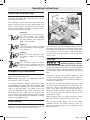
Tool Tips
Always hold the saw by the
insulated gripping surfaces
on the front of the tool and the switch handle.
Failure to hold the tool by the insulated gripping
surface may result in electric shock or electrocu-
tion if sawing into a blind area where live wiring
exits.
Always be certain that smaller workpieces are
securely fastened to a bench or other support.
Larger panels may be held in place by clamps on
a bench or sawhorses.
To begin a cut, clearly mark the cutting line, and
rest the front of the footplate on the work. En-
gage the switch, and move the blade into the
work using only enough forward pressure to
keep the blade cutting steadily. Do not force,
as this will not make the saw cut faster; let the
blade do the work.
When sawing metal or similar materials, apply
coolant/lubricant alongside the cutting line.
Use of reverse-tooth blade such as the Bosch
T101BR requires the orbital setting to be “0”
and that downward pressure be applied to the
top of the saw.
(22)
(23)
(12)
(11)
(23)
(17)
Fig. 9
160992A7EF_GST18V50_202203.indd 13 3/25/22 11:47 AM

-14-
Operating Tips
Blade Selection
• Choose blades carefully, as the ability of the
jigsaw to make the fastest cuts, to follow tight
curves, to achieve the smoothest finish and/
or to maximize the life of the blade are direct-
ly related to the type of blade used.
• Always use a blade that is appropriate for the
cutting task.
• Always make a test cut in a piece of scrap ma-
terial.
• For tight curves it is best to use a narrow or
scroll blade.
• Most jigsaw blades have upwardpointing
teeth, which helps to pull the jigsaw against
the workpiece and minimizes vibration.
Blades with upward-pointing teeth produce
a clean cut on the bottom of the workpiece.
• Blades with downward-pointing teeth (re-
verse-tooth blade) can be used to produce a
clean cut on the top of the workpiece (that
side that faces the jigsaw’s footplate), such
as when cutting an already-installed counter-
top from the top. When using reverse-tooth
blades, downward force must be applied to
the jigsaw.
• Blades with teeth that point straight out (rath-
er than up or down) allow splinter-free cutting
on both sides of the workpiece. When using
such blades, downward force must be applied
to the jigsaw.
• The following types of blades should only be
used with orbital Setting 0:
– Blades with teeth that point downward (re-
verse-tooth blades).
– Blades with teeth that point straight out
rather than up or down.
– Carbide-tipped blades.
– Grit-edge blades.
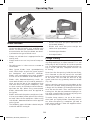
Plunge Cutting
Plunge cutting is useful and time-saving in mak-
ing rough openings in softer materials. It is not
necessary to drill a hole for an inside or pocket
cut. The longest blade to be used for plunge cut-
ting is 3-1/8” (80 mm). Footplate must be set
0° setting.
Draw lines for the opening, hold the saw firmly,
tilt it forward so that the toe of the saw foot
rests on the work, but with the blade well clear
of the work. Turn the tool on and run at top
speed, and then very gradually lower the blade
(Fig. 10).
When it touches, continue pressing down on the
toe of the saw foot slowly pivoting the saw like
a hinge until the blade cuts through and the foot
rests flat on the work. Then saw ahead on the
cutting line. We do not recommend plunge cut-
ting with a scroll blade. Do not try to plunge cut
into hard materials such as steel.
To make sharp corners, cut up to the corner,
then back up slightly before rounding the cor-
ner. After the opening is complete, go back to
each corner and cut it from the opposite direc-
tion to square it off.
Fig. 10
160992A7EF_GST18V50_202203.indd 14 3/25/22 11:47 AM

-15-
Operating Tips
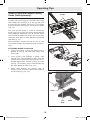
JA1010 Circle and Parallel Cutting
Guide (Sold separately)
The JA1010 is used for fast and accurate
straight and circle cutting. It includes the guide,
two clamps for attaching it to the jig saw, and
a center pin for guiding circle cuts. The clamps
and the centering pin can be stored on the guide
(Fig. 11).
One end of the clamp is used to attach the
guide’s bar to jig saws that have narrow tops on
their footplate mounting slots A and the other
end is used to attach the guide’s bar to jig saws
that have wide tops on their footplate mounting
slots B (Fig. 12).
When possible, attach the bar to the jig saw
using both clamps for enhanced grip and preci-
sion.
ATTACHING GUIDE TO JIG SAW
1. Orient the clamp so that the proper end is
placed on the jig saw foot from either side
of the tool.
2. Insert guide’s bar through a clamp, then
through the slots provided in foot, with the
guide’s fence orientated correctly for the in-
tended application, parallel cutting or circle
cutting. (If possible, place second clamp on
bar from opposite side of jig saw.)
3. Place lock knob(s) on proper side of
clamp(s) and securely tighten lock knob(s)
on the clamp(s) (Fig. 13).
Fig. 11
B
A
Fig. 12
Fig. 13
GuideLock
Knob
Clamp
Center
Pin
Clamps
160992A7EF_GST18V50_202203.indd 15 3/25/22 11:47 AM

-16-
Operating Tips
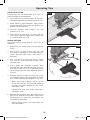
PARALLEL CUTTING
Parallel cuts can be made from 5/8” to 6” in
from the edge of the workpiece.
1. The guide fence surface needs to be posi-
tioned ALONGSIDE the workpiece (Fig. 14).
2. Hook clamp(s) onto footplate, adjust fence
to desired width and place lock knob(s) on
proper side of clamp(s).
3. Securely tighten lock knob(s) on the
clamp(s) (Fig. 13).
4. Insert battery pack onto jig saw, hold the
saw firmly, squeeze trigger and slowly push
the saw forward (Fig. 14).
CIRCLE CUTTING
Circle cuts can be made from 5” to 16-1/2” in
diameter.
1. Determine the center point of the desired
circle.
2. Drill a 3/16” (5 mm) center hole 7/8” (23
mm) deep in workpiece. (For enhanced pre-
cision, drill the hole using a drill press, if
possible).
3. Drill or plunge cut near the circle’s edge,
turn saw off, and disconnect battery pack
from the tool.
4. Insert guide bar through a clamp, then
through the slots provided in foot, from ei-
ther side of foot (Fig. 13). (If possible, place
second clamp on bar from opposite side of
jig saw).
5. Remove guide pin from end of guide, push
pin through proper hole provided in guide,
then into center hole of workpiece (Fig. 15).
– When used with a Bosch JS572 jig saw
or the GST18V-50 / GST18V-50B cordless
jig saw, the holes labeled for the JS572
should be used.
– For other jig saws, one of the other holes
should be used.
6. Measure the distance from the center of the
hole to the desired circle radius. Adjust that
measurement as necessary to account for
the width of the blade:
– When cutting a hole, cut from inside the
intended radius.
Fig. 14
Fig. 15
Wedge
Center Pin
160992A7EF_GST18V50_202203.indd 16 3/25/22 11:47 AM

-17-
Operating Tips
– When cutting wheels or discs, cut from
the outside the intended radius.
7. Hook clamp(s) onto footplate, and position
the guide to that adjusted radius measure-
ment.
8. Place lock knob(s) on proper side of
clamp(s) and securely tighten lock knob(s)
on the clamp(s) (Fig. 12).
9. Insert battery pack onto jig saw, hold the
saw firmly, squeeze trigger and slowly push
the saw forward.
CIRCLE-CUTTING TIPS:
• Place small wedges in the cut as shown in Fig.
15, to keep the inner circle from spreading
when near the end of the cut.
• Use a thick jig saw blade, such as the Bosch
T101TP or T144DP whenever possible.
• Make sure that the jig saw’s orbital setting is
at 0 (zero).
• Cut slowly so the blade will stay straight in
the cut.
160992A7EF_GST18V50_202203.indd 17 3/25/22 11:47 AM

-18-
Maintenance
Service
NO USER SERVICEABLE
PARTS INSIDE. Preventive
maintenance performed by un au thorized per-
sonnel may result in misplacing of internal
wires and components which could cause seri-
ous hazard. We recom mend that all tool service
be performed by a Bosch Factory Service Center
or Authorized Bosch Service Station.
Batteries
Be alert for battery packs that are nearing
their end of life. If you notice decreased tool
performance or significantly shorter running
time between charges then it is time to replace
the battery pack. Failure to do so can cause the
tool to operate improperly or damage the char-
ger.
Tool Lubrication
Your Bosch tool has been properly lubricated
and is ready for use.
Motors
The motor in your tool has been engineered for
many hours of dependable service. To maintain
peak efficiency of the motor, we recommend it
be examined every six months. Only a genuine
Bosch replacement motor specially designed for
your tool should be used.
Bearings
Bearings which become noisy (due to heavy load
or very abrasive material cutting) should be re-
placed at once to avoid overheating and motor
failure.
Cleaning
Certain cleaning agents and
solvents damage plastic
parts. Some of these are: gasoline, carbon tetra-
chloride, chlorinated cleaning solvents, ammo-
nia and household detergents that contain am-
monia.
Ventilation openings and switch levers must be
kept clean and free of foreign matter. Do not
attempt to clean by inserting pointed objects
through opening.
CLEANING BLADE HOLDER
Clean the saw blade holder regularly. For this,
remove the saw blade from the tool and lightly
tap footplate on a level surface.
Regularly spray penetrating oil onto the saw
blade holder.
Check the guide roller regularly. If worn, it must
be replaced through an authorized Bosch Fac-
tory Service Center
Lubricate the guide roller occasionally with a
drop of oil.
To avoid accidents, always disconnect the battery pack from tool before ser-
vicing or cleaning.
Accessories and Attachments
The use of any other attachments or accessories not specified in this manual
may create a hazard.
Store accessories in a dry and temperate environment to avoid corrosion and deterioration.
Standard equipment Optional accessories and attachments
- JA1013 Anti splinter insert
- Bosch T-shank jig saw blade
- JA1012 Articulating Dust Extraction Kit
- Non-Marring Overshoe
- JA1010 Circle and parallel cutting guide
- Carrying bag
- Other Bosch T-shank jig saw blades
160992A7EF_GST18V50_202203.indd 18 3/25/22 11:47 AM

-19-
page heading
Symboles relatifs à la sécurité
Les définitions ci-dessous décrivent le niveau de gravité pour chaque terme signalant un danger.
Veuillez lire le mode d’emploi et lire la signification de ces symboles.
!
C’est le symbole d’alerte relatif à la sécurité. Il est utilisé pour vous avertir de
l’existence possible d’un danger de lésion corporelle. Obéissez à tous les messages
relatifs à la sécurité qui suivent ce symbole pour éviter tout risque de blessure ou
même de mort.
DANGER indique une situation dangereuse qui, si elle n’est pas évitée, causera la
mort d’une personne ou une blessure grave.
AVERTISSEMENT indique une situation dangereuse qui, si elle n’est pas évitée,
pourrait causer la mort d’une personne ou une blessure grave.
MISE EN GARDE indique une situation dangereuse qui, si elle n’est pas évitée,
pourrait causer une blessure légère ou modérée.
Lisez toutes les consignes de sécurité, instructions, illustrations et spécifications
fournies avec cet outil électrique. Le non-respect de toutes les instructions figurant ci-
après pourrait causer un choc électrique, un incendie et/ou des blessures graves.
CONSERVEZ TOUS LES AVERTISSEMENTS ET TOUTES LES CONSIGNES DE SÉCURITÉ POUR RÉFÉRENCE FUTURE.
Dans les avertissements, le terme « outil électroportatif » se rapporte à votre outil branché sur le secteur (avec fil) ou à
votre outil alimenté par piles (sans fil).
1. Sécurité du lieu de travail
a. Maintenez le lieu de travail propre et bien éclairé. Les
risques d’accident sont plus élevés quand on travaille dans
un endroit encombré ou sombre.
b. N’utilisez pas d’outils électroportatifs dans des atmo-
sphères explosives, comme par exemple en présence
de gaz, de poussières ou de liquides inflammables. Les
outils électroportatifs produisent des étincelles qui ris-
quent d’enflammer les poussières ou les vapeurs.
c. Éloignez les enfants et les visiteurs quand vous vous
servez d’un outil électroportatif. Vous risquez une perte
de contrôle si on vous distrait.
2. Sécurité électrique
a. Les fiches des outils électroportatifs doivent corre-
spondre à la prise. Il ne faut absolument jamais modifier
la fiche. N’utilisez pas d’adaptateur de prise avec des out-
ils électroportatifs munis d’une fiche de terre. Le risque
de choc électrique est moindre si on utilise une fiche non
modifiée sur une prise qui lui correspond.
b. Évitez tout contact du corps avec des surfaces reliées à
la terre tels que tuyaux, radiateurs, gazinières ou réfri-
gérateurs. Le risque de choc électrique augmente si votre
corps est relié à la terre.
c. N’exposez pas les outils électroportatifs à la pluie ou à
l’humidité. Si de l’eau pénètre dans un outil électroporta-
tif, le risque de choc électrique augmente.
d. Ne maltraitez pas le cordon. Ne vous en servez jamais
pour transporter l’outil électroportatif, pour le tirer ou pour
le débrancher. Éloignez le cordon de la chaleur, des huiles,
des arêtes coupantes ou des pièces mobiles. Les cordons
abîmés ou emmêlés augmentent les risques de choc élec-
trique.
e. Si vous utilisez un outil électroportatif à l’extérieur,
employez une rallonge conçue pour l’extérieur. Ces ral-
longes sont faites pour l’extérieur et réduisent le risque de
choc électrique.
f. S’il est absolument nécessaire d’utiliser l’outil électro-
portatif dans un endroit humide, utilisez une alimen-
tation protégée par un disjoncteur de fuite de terre
(GFCI). L’utilisation d’un disjoncteur GFCI réduit les ris-
ques de choc électrique.
3. Sécurité personnelle
a. Restez concentré, faites attention à ce que vous faites,
et servez-vous de votre bon sens lorsque vous utilisez
un outil électroportatif. N’employez pas d’outils élec-
troportatifs quand vous êtes fatigué ou sous l’emprise de
drogues, d’alcool ou de médicaments. Quand on utilise des
outils électroportatifs, il suffit d’un moment d’inattention
pour causer des blessures corporelles graves.
Avertissements généraux concernant la sécurité des outils lectroportatifs
160992A7EF_GST18V50_202203.indd 19 3/25/22 11:47 AM

-20-
page headingAvertissements généraux concernant la sécurité des outils lectroportatifs
b. Utilisez des équipements de sécurité person-
nelle. Portez toujours une protection oculaire. Le port
d’équipements de sécurité tels que des masques anti-
poussières, des chaussures de sécurité antidérapantes,
des casques de chantier et des protecteurs d’oreilles dans
des conditions appropriées réduira le risque de blessure
corporelle.
c. Évitez les démarrages intempestifs. Assurez-vous que
l’interrupteur est dans la position arrêt (Off) avant de
brancher l’outil dans une prise de courant et/ou un bloc-
piles, de le ramasser ou de le transporter. Le transport
d’un outil électroportatif avec le doigt sur la gâchette ou le
branchement de cet outil quand l’interrupteur est en posi-
tion de marche (ON) est une invite aux accidents.
d. Enlevez toutes les clés de réglage avant de mettre
l’outil électroportatif en marche. Si on laisse une clé sur
une pièce tournante de l’outil électroportatif, il y a risque
de blessure corporelle.
e. Ne vous penchez pas. Conservez toujours une bonne
assise et un bon équilibre. Ceci vous permettra de mieux
maîtriser l’outil électroportatif dans des situations inatten-
dues.
f. Habillez-vous de manière appropriée. Ne portez pas
de vêtements amples ou de bijoux. Attachez les cheveux
longs. N’approchez pas les cheveux, les vêtements ou les
gants des pièces en mouvement. Les vêtements amples,
les bijoux ou les cheveux longs risquent d’être happés par
les pièces en mouvement.
g. Si l’outil est muni de dispositifs permettant le raccorde-
ment d’un système d’aspiration et de collecte des pous-
sières, assurez-vous que ces dispositifs sont raccordés
et utilisés correctement. L’utilisation d’un dépoussiéreur
peut réduire les dangers associés à l’accumulation de
poussière.
h. Ne laissez pas la familiarité résultant de l’utilisation
fréquente des outils vous inciter à devenir
complaisant(e) et à ignorer les principes de sécurité
des outils. Une action négligente pourrait causer des bles-
sures graves en une fraction de seconde.
4. Utilisation et entretien des outils électro-
portatifs
a. Ne forcez pas sur l’outil électroportatif. Utilisez l’outil
électroportatif qui convient à la tâche à effectuer. L’outil
qui convient à la tâche fait un meilleur travail et est plus sûr
à la vitesse pour lequel il a été conçu.
b. Ne vous servez pas de l’outil électroportatif si son in-
terrupteur ne parvient pas à le mettre en marche ou à
l’arrêter. Tout outil électroportatif qui ne peut pas être
commandé par son interrupteur est dangereux et doit être
réparé.
c. Débranchez la fiche de la prise secteur et/ou retirez le
bloc-piles de l’outil électrique (s’il est amovible) avant
d’y apporter de quelconques modifications, de changer
d’accessoire ou de ranger l’outil électrique. De telles
mesures de sécurité préventive réduisent le risque de dé-
marrage intempestif de l’outil électroportatif.
d. Rangez les outils électroportatifs dont vous ne vous
servez pas hors de portée des enfants et ne permettez
pas à des personnes qui ne connaissent pas l’outil élec-
troportatif ou qui ignorent ces consignes de s’en servir.
Les outils électroportatifs sont dangereux dans les mains
d’utilisateurs inexpérimentés.
e. Entretenez de façon appropriée les outils électriques
et les accessoires. Assurez-vous que les pièces en mou-
vement sont bien alignées et qu’elles ne se coincent pas,
qu’il n’y a pas de pièces cassées ou qu’il n’existe aucune
situation pouvant affecter le fonctionnement de l’outil
électrique. Si l’outil est abîmé, faites-le réparer avant de
l’utiliser. De nombreux accidents sont causés par des out-
ils électroportatifs mal entretenus.
f. Maintenez les outils coupants affûtés et propres.Les
outils coupants entretenus correctement et dotés de
bords tranchants affûtés sont moins susceptibles de
coincer et sont plus faciles à maîtriser.
g. Utilisez l’outil électroportatif, les accessoires et les
embouts d’outil, etc. conformément à ces instructions,
en tenant compte des conditions de travail et des travaux à
réaliser. L’emploi d’outils électroportatifs pour des tâches
différentes de celles pour lesquelles ils ont été prévus peut
résulter en une situation dangereuse.
h. Gardez les poignées et les surfaces de préhension pro-
pres, sèches et exemptes de toute trace d’huile ou de
graisse. Les poignées et les surfaces de préhension glis-
santes ne permettent pas une manipulation et un contrôle
sûrs de l’outil dans des situations inattendues.
5. Utilisation et entretien des outils à piles
a. Rechargez les piles uniquement avec le chargeur spéci-
fié par le fabriquant. Un chargeur qui convient à un type
de bloc-piles peut entraîner un risque d’incendie quand il
est utilisé avec un autre bloc-piles.
b. Utilisez des outils électroportatifs uniquement avec
les bloc-piles spécifiquement désignés pour eux.
L’utilisation de tout autre bloc-piles peut créer un risque de
blessures et d’incendie.
c. Lorsque le bloc-piles n’est pas utilisé, gardez-le à dis-
tances d’autres objets métalliques tels que des trom-
bones, des pièces de monnaie, des clés, des clous, des
vis ou de tout autre objet métallique pouvant faire une
connexion entre une borne et une autre. Court-circuiter
les bornes des piles peut causer des brûlures ou un in-
cendie.
160992A7EF_GST18V50_202203.indd 20 3/25/22 11:47 AM
La page charge ...
La page charge ...
La page charge ...
La page charge ...
La page charge ...
La page charge ...
La page charge ...
La page charge ...
La page charge ...
La page charge ...
La page charge ...
La page charge ...
La page charge ...
La page charge ...
La page charge ...
La page charge ...
La page charge ...
La page charge ...
La page charge ...
La page charge ...
La page charge ...
La page charge ...
La page charge ...
La page charge ...
La page charge ...
La page charge ...
La page charge ...
La page charge ...
La page charge ...
La page charge ...
La page charge ...
La page charge ...
-
 1
1
-
 2
2
-
 3
3
-
 4
4
-
 5
5
-
 6
6
-
 7
7
-
 8
8
-
 9
9
-
 10
10
-
 11
11
-
 12
12
-
 13
13
-
 14
14
-
 15
15
-
 16
16
-
 17
17
-
 18
18
-
 19
19
-
 20
20
-
 21
21
-
 22
22
-
 23
23
-
 24
24
-
 25
25
-
 26
26
-
 27
27
-
 28
28
-
 29
29
-
 30
30
-
 31
31
-
 32
32
-
 33
33
-
 34
34
-
 35
35
-
 36
36
-
 37
37
-
 38
38
-
 39
39
-
 40
40
-
 41
41
-
 42
42
-
 43
43
-
 44
44
-
 45
45
-
 46
46
-
 47
47
-
 48
48
-
 49
49
-
 50
50
-
 51
51
-
 52
52


Bosch GST18V-50N Manuel utilisateur
- Catégorie
- Outils électroportatifs
- Taper
- Manuel utilisateur
dans d''autres langues
- English: Bosch GST18V-50N User manual
- español: Bosch GST18V-50N Manual de usuario