GE UVW9301BLTS Le manuel du propriétaire
- Catégorie
- Hottes
- Taper
- Le manuel du propriétaire
Ce manuel convient également à

Write the model and serial
numbers here:
Model # _________________
Serial # _________________
You can find them on a label
on the inside of the hood.
ESPAÑOL
Para consultar una version en
español de este manual de
instrucciones, visite nuestro sitio de
internet GEAppliances.com.
WALL HOODS
49-2000896 Rev. 1 05-21 GEA
GE is a trademark of the General Electric Company. Manufactured under trademark license.
UVW9301
UVW9361
OWNER’S MANUAL &
INSTALLATION
INSTRUCTIONS
SAFETY INFORMATION .............3
USING THE HOOD
Controls ..................................5
Chef Connect ............................ 6
Wi-Fi Connect ............................ 6
CARE AND CLEANING
Filters ....................................7
Surfaces ..................................8
Lights ....................................8
INSTALLATION INSTRUCTIONS ... 9
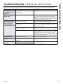
TROUBLESHOOTING TIPS ..........21
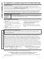
LIMITED WARRANTY .............. 22
ACCESSORIES ...................... 23
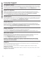
CONSUMER SUPPORT ............. 24
FRANÇAIS
Pour une version français de
ce manuel d’utilisation, veuillez
visiter notre site web à l’adresse
GEAppliances.com.

2 49-2000896 Rev. 1
THANK YOU FOR MAKING GE APPLIANCES A PART OF YOUR HOME.
Whether you grew up with GE Appliances, or this is your first, we’re happy to have you in the family.
We take pride in the craftsmanship, innovation and design that goes into every GE Appliances
product, and we think you will too. Among other things, registration of your appliance ensures that we
can deliver important product information and warranty details when you need them.
Register your GE appliance now online. Helpful websites and phone numbers are available in the
Consumer Support section of this Owner’s Manual. You may also mail in the pre-printed registration
card included in the packing material.

49-2000896 Rev. 1 3
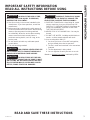
SAFETY INFORMATION
IMPORTANT SAFETY INFORMATION
READ ALL INSTRUCTIONS BEFORE USING
READ AND SAVE THESE INSTRUCTIONS
WARNING
TO REDUCE THE RISK OF FIRE,
ELECTRIC SHOCK OR INJURY TO PERSONS,
OBSERVE THE FOLLOWING:
A. Use this unit only in the manner intended by the
manufacturer. If you have questions, contact the
manufacturer.
B. Before servicing or cleaning unit, switch power off
at service panel and lock the service disconnecting
means to prevent power from being switched
on accidentally. When the service disconnecting
means cannot be locked, securely fasten a
prominent warning device, such as a tag, to the
service panel.
C. Do not use this unit with any solid-state speed
control device.
D. This unit must be grounded.
CAUTION
FOR GENERAL VENTILATING USE
ONLY. DO NOT USE TO EXHAUST HAZARDOUS
OR EXPLOSIVE MATERIALS AND VAPORS.
CAUTION
TO REDUCE RISK OF FIRE AND
TO PROPERLY EXHAUST AIR, BE SURE TO DUCT
AIR OUTSIDE. DO NOT VENT EXHAUST AIR INTO
SPACES WITHIN WALLS OR CEILINGS OR INTO
ATTICS, CRAWL SPACES OR GARAGES.
WARNING
TO REDUCE THE RISK OF INJURY
TO PERSONS IN THE EVENT OF A RANGE TOP
GREASE FIRE, OBSERVE THE FOLLOWING*:
A. SMOTHER FLAMES with a close-fitting lid, cookie
sheet or metal tray, then turn off the burner. BE
CAREFUL TO PREVENT BURNS. If the flames do
not go out immediately, EVACUATE AND CALL
THE FIRE DEPARTMENT.
B. NEVER PICK UP A FLAMING PAN—You may be
burned.
C. DO NOT USE WATER, including wet dishcloths or
towels—a violent steam explosion will result.
D. Use an extinguisher ONLY if:
1. You know you have a Class ABC extinguisher,
and you already know how to operate it.
2. The fire is small and contained in the area where
it started.
3. The fire department is being called.
4. You can fight the fire with your back to an exit.
* Based on “Kitchen Fire Safety” published by NFPA.

4 49-2000896 Rev. 1
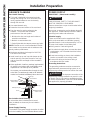
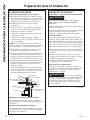
How to Remove Protective Shipping Film and Packaging Tape
Carefully grasp a corner of the protective shipping film
with your fingers and slowly peel it from the appliance
surface. Do not use any sharp items to remove the film.
Remove all of the film before using the appliance for the
first time.
To assure no damage is done to the finish of the
product, the safest way to remove the adhesive from
packaging tape on new appliances is an application of
a household liquid dishwashing detergent. Apply with a
soft cloth and allow to soak.
NOTE: The adhesive must be removed from all parts.
NOTE: For further cleaning instructions/suggestions,
please refer to the Care And Cleaning section.
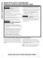
SAFETY INFORMATION
IMPORTANT SAFETY INFORMATION
READ ALL INSTRUCTIONS BEFORE USING
READ AND SAVE THESE INSTRUCTIONS
WARNING
TO REDUCE THE RISK OF A
RANGE TOP GREASE FIRE:
A. Never leave surface units unattended at high
settings. Boilovers cause smoking and greasy
spillovers that may ignite. Heat oils slowly on
medium settings.
B. Always turn hood ON when cooking at high heat or
when flambéing food (i.e. Crepes Suzette, Cherries
Jubilee, Peppercorn Beef Flambé).
C. Clean ventilating fans frequently. Grease should not
be allowed to accumulate on fan or filter.
D. Use proper pan size. Always use cookware
appropriate for the size of the surface element.
WARNING
TO REDUCE THE RISK OF FIRE,
ELECTRIC SHOCK OR INJURY TO PERSONS,
OBSERVE THE FOLLOWING:
A. Installation work and electrical wiring must be
done by qualified person(s) in accordance with all
applicable codes and standards, including fire-rated
construction.
B. Sufficient air is needed for proper combustion and
exhausting of gases through the flue (chimney) of
fuel burning equipment to prevent back drafting.
Follow the heating equipment manufacturer’s
guidelines and safety standards such as those
published by the National Fire Protection
Association (NFPA), the American Society for
Heating, Refrigeration and Air Conditioning
Engineers (ASHRAE) and the local code authorities.
C. When cutting or drilling into wall or ceiling, do not
damage electrical wiring and other hidden utilities.
D. Ducted fans must always be vented to the outdoors.
E. When applicable, install any makeup (replacement)
air system in accordance with local building
code requirements. Visit GEAppliances.com for
available makeup air solutions.
F. Turn off breaker to adjacent rooms while working.
WARNING
TO REDUCE THE RISK OF FIRE,
USE ONLY METAL DUCTWORK.
Ŷ'RQRWDWWHPSWWRUHSDLURUUHSODFHDQ\SDUWRI\RXU
hood unless it is specifically recommended in this
manual. All other servicing should be referred to a
qualified technician.

49-2000896 Rev. 1 5
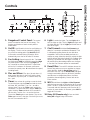
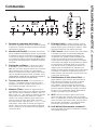
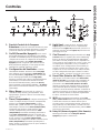
Controls
USING THE HOOD: Controls
1. Rangehood Control Panel: The control
panel is located on the front of the canopy. The
position and function of each control pad are
noted below.
2. On/Off: On/Off switch for the fan and lighting up
the display. The fan can be operated by tapping
any of the fan setting pads. Hold On/Off pad for
3 seconds to activate Delay Off feature, which
automatically turns the fan off after 15 minutes.
3. Fan Setting: Speed control for fan. Tap Low
for LOW speed. Med for MEDIUM speed and High
for HIGH speed. Press and hold the High pad
for 3 seconds to activate the BOOST speed that
will run for 10 minutes. On Remote, press Ÿ to
increase fan speed, press ź to decrease fan speed,
including Boost.
4. Plus and Minus: The plus (+) and minus (–)
pads control the time for the clock and the timer.
To add time, tap the + pad. To subtract time, tap
the – pad.
5. Timer: Sets a timer for cooking or sets the clock.
To start the timer, tap the Timer pad and the clock
will show “HR” and “MIN”. Tap + or – to add or
subtract time. Tap on the Timer again to start the
countdown. To cancel the timer, tap the Timer pad
again. Hold the Timer pad down for 3 seconds to
set the clock. Tap the + or – to set the the hour.
Tap on the Timer again to set minutes. Tap on the
Timer again to lock in the time. Clock will sync once
the unit is connected to Wi-Fi.
6. Light: Controls the lights. Tap the Light pad to
turn the lights on fully. Tap the Light pad again and
the lights will dim. Tap the Light pad a third time to
turn off the lights.
7. Chef Connect: Hold the Chef Connect pad
down for 3 seconds to activate the Bluetooth
®
. This
is a Bluetooth
®
pairing feature for use with other
compatible Chef Connect enabled products on a
cooktop or range. When the device is paired, the light
and fan will turn ON at the Default Sync Settings upon
receiving a command from the range or cooktop. It
will remain ON at that setting until the user changes
it. See the Chef Connect section for more details.
8. Reset Filter: The red LED indicator above the
Reset Filter pad turns on as a reminder to change
/clean the filter. Hold the Reset Filter pad for 3
seconds to turn off. Tap the Reset Filter pad again
to begin recalculating the time. While this indicator
reminds user to change/clean filters, the filters
should be cleaned regularly. Please refer to the
Filters section.
9. Wi-Fi: Hold down the Light and Chef Connect
pads for three seconds to activate the Wi-Fi connect
mode. The Wi-Fi symbol above the clock blinks for
3 seconds and then becomes solid. See the Wi-Fi
section for more details. On Remote, press Wi-Fi to
toggle Wi-Fi function.
10. Delay Off (Remote only): Press and hold
Delay Off to toggle Delay Off function.
3
4
25678
1 9
10
Remote Control
6
9
2
7
3

6 49-2000896 Rev. 1
Wi-Fi Connect
USING THE HOOD: Chef Connect / Wi-Fi Connect
* Compatible Apple or Android devices and home Wi-Fi network required.
Connecting your Wi-Fi Connect Enabled hood (on some models)
Your GE Appliances hood is designed to provide you with two-way communication between your appliance and smart
device. By using the GE Appliances Wi-Fi Connect features, you will be able to control essential hood operations such
as fan speed, light functions, timer/clock function, delay off and filter reset using your smartphone or tablet.*
What you will need
Your GE Appliances hood uses your existing home Wi-Fi
network to communicate between the appliance and your
smart device. In order to setup your GE Appliances hood,
you will need to gather some information:
1. Each GE Appliances hood has a connected
appliance information label that includes an
Appliance Network Name and Password. These
are the two important details that you will need to
connect to the appliance. The label is located on the
side of the unit behind the filters.
2. Have your smart phone or tablet ready with the ability
to access the internet and download apps.
3. You will need to know the password of your home
Wi-Fi router. Have this password ready while you are
setting up your GE Appliances hood.
Connect your GE Appliances hood
1. On your smart phone or tablet visit
GEAppliances.com/connect to learn more about
connected appliance features and to download the
appropriate app.
2. Follow the app onscreen instructions to connect your
GE Appliances hood.
3. Once the process is complete, the connection light
located on your GE Appliances hood display will stay
on solid and the app will confirm you are connected.
4. If the connection light does not turn on or is blinking,
follow the instructions on the app to reconnect. If
issues continue please call 800.220.6899 and ask for
assistance regarding hood wireless connectivity.
To connect additional smart devices, repeat steps 1 and 2.
Note that any changes or modifications to the remote
enable device installed on this hood that are not
expressly approved by the manufacturer could void the
user’s authority to operate the equipment.
Chef Connect Operation Bluetooth
®
Connection
To pair with another device:
To start the pairing process on the hood, press and hold
the Chef Connect button for 3 seconds. The backlight
for all the icons will light up until the hood is paired with
the range or other device. If the pairing is successful,
the Bluetooth
®
symbol above the clock will turn on and
become solid.
It will time out after 2 minutes if the pairing is not
completed, after which the pairing sequence will need to
be restarted.
To cancel pairing:
To cancel the pairing, hold the Chef Connect button
down for 3 seconds and then turn off the hood.
Default Sync Settings:
The factory default setting for the light will be the brightest.
The factory default setting for the fan sync will be OFF.
The user can change the Default Sync Settings by
pressing and holding the Low button for 3 seconds. This
will enter the Default Settings Mode. Once in this mode,
the backlights for all buttons will blink on/off indefinitely
and the fan and light will switch to the current Default
Sync Setting, so the user knows what the current default
value is. At this time, set the light and fan to the desired
default levels. Once the user is satisfied with the selection,
press and hold the Off button for 3 seconds. This will exit
this mode. At that time the backlights will stop blinking and
the state of the fan and light will change back to their prior
state before entering the Default Settings Mode.
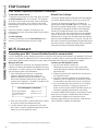
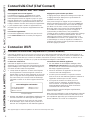
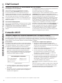
Chef Connect
Sample Label
Connected Appliance Information
FCC ID: ZKJ-WCATA005
IC: 10229A-WCATA001
MAC ID: ************
Network: ************
Password: **********

49-2000896 Rev. 1 7
Be sure the circuit breaker is off and all surfaces are cool before cleaning or servicing any part of the vent hood.
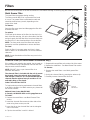
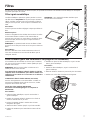
Metal Grease Filter
The metal filters trap grease during cooking.
The filters must ALWAYS be in place when the hood
is in use. The grease filters are dishwasher-safe and
should be cleaned every month, depending on the
usage of the hood.
To remove:
Open the filter cover panel and disengage the filter lock
to release the filter.
To replace:
Fit the tabs at the bottom of the filter into the slots in the
back of the filter opening. Lift up the front side of the filter
and push gently until the filter locks into place. Make sure
the filter lock is in the closed position to secure the filter.
NOTE: The front panel covers the filters and must be
pressed up and then pulled down to access the filters.
To clean:
Swish the filter in hot soapy water and rinse in clean
water or wash it in the dishwasher. Do not use abrasive
cleansers.
NOTE: Some discoloration of the filter may occur in the
dishwasher.
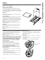
Charcoal Filter (for recirculation installation only)
If the model is not vented to the outside, the air needs to
be recirculated through a disposable charcoal filter that
helps remove smoke and odors.
NOTE: DO NOT rinse, or put charcoal filter in an
automatic dishwasher.
The charcoal filter is included with the unit. It cannot
be cleaned, It must be replaced when Reset Filter
LED indicator comes on. It is recommended that the
charcoal filter be replaced every 6 months or if it is
noticeably dirty or discolored.
Order Charcoal Filter UXCF91
To inquire about purchasing replacement charcoal filters
or to find the location of a dealer nearest you, please call
our toll-free number:
National Parts Center 800.626.2002
In Canada, call 800.661.1616 or visit geappliances.ca
To install:
1. Remove the metal filters—see Metal Grease Filter
section.
2. Install the charcoal filter mounts to either side of the
motor using three screws per side.
3. Insert the tab on the charcoal filter into the triangular
slot on the mount.
4. Clip the charcoal filter in until it is locked.
5. Repeat with second filter on the other side of the motor.
6. Replace the metal filters - See Metal Grease Filter section.
To remove:
1. Remove the metal filters—see Metal grease filter
section.
2. Unclip the charcoal filter by pressing the release clip.
3. Carefully remove charcoal filter from tab.
Filters
CARE AND CLEANING: Filters
Charcoal
Filter Mount

8 49-2000896 Rev. 1
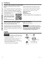
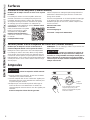
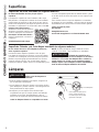
Lights
Painted Surfaces and Black Stainless Color (on some models)
Do not use a steel wool pads or other abrasive
cleaners; they will scratch the surface.
Clean grease-laden surfaces of the hood frequently. To
clean the hood surface, use a hot, damp cloth with a
mild detergent suitable for painted surfaces. About one
tablespoon of ammonia may be added to the water. Use
a clean, hot, damp cloth to remove soap. Dry with a dry,
clean cloth.
NOTE: When cleaning, take care not to come in contact
with filters and other surfaces.
CAUTION
When cleaning the hood surfaces,
be certain that you do not touch the light with moist
hands or cloth. A warm or hot light may break if
touched with a moist surface. Always let the light
cool completely before cleaning around it.
CAUTION
Allow lights to cool before touching.
1. Before attempting to replace the lights, make sure that
the light switch is turned off.
2. Rotate light counterclockwise to unlock and pull out.
Wearing latex gloves may offer a better grip.
3. Replace with new light of same type, making sure
pins are inserted properly into the sockets of the lamp
holder and turn clockwise to lock.
All lamps need to be GU10 compatible.
Surfaces
CARE AND CLEANING: Surfaces / Lights
Rotate the lamp until the
pins are located in narrow
neck of the socket to lock.
Lamp
Holder
Stainless Steel Surfaces (on some models)
Do not use a steel wool pad; it will scratch the
surface.
To clean the stainless steel surface, use warm sudsy
water or a stainless steel cleaner or polish. Always wipe
the surface in the direction of the brush line. Follow
the cleaner instructions for cleaning the stainless steel
surface. Cleaners with oxalic acid such as Bar Keepers
Friend Soft Cleanser™ will
remove surface rust, tarnish, and
small blemishes. To receive a
coupon for a trial sample of Bar
Keepers Friend Soft Cleanser™
follow the link below or scan the
QR Code.
www.barkeepersfriend.com/ge
Use only a liquid cleanser free of grit and rub in the
direction of the brush lines with a damp soft sponge.
To inquire about purchasing stainless steel appliance
cleaner or polish, or to find the location of a dealer
nearest you, please call our toll-free number:
National Parts Center
800.626.2002
GEApplianceParts.com
In Canada, call 800.661.1616 or visit geappliances.ca

49-2000896 Rev. 1 9
Installation
Instructions
“If you have questions, call GE Appliances at 800.GE.CARES (800.432.2737)
or visit our website at: GEAppliances.com. In Canada, visit GEAppliances.ca or call 800.561.3344.
INSTALLATION INSTRUCTIONS
BEFORE YOU BEGIN
Read these instructions completely and carefully.
Ŷ
IMPORTANT — Save these
instructions for local inspector’s use.
Ŷ
IMPORTANT — Observe all governing
codes and ordinances.
Ŷ
Note to Installer – Be sure to leave these
instructions with the Consumer.
Ŷ
Note to Consumer – Keep these instructions for
future reference.
Ŷ
Skill level – Installation of this vent hood requires
basic mechanical and electrical skills.
Ŷ
Completion time – Approximately 1 to 3 hours
Ŷ
Proper installation is the responsibility of the
installer.
Ŷ
Product failure due to improper installation is not
covered under the Warranty.
FOR YOUR SAFETY
WARNING
Before beginning the installation,
switch power off at service panel and lock the
service disconnecting means to prevent power from
being switched on accidentally. When the service
disconnecting means cannot be locked, securely
fasten a prominent warning device, such as a tag,
to the service panel.
CAUTION
Due to the weight and size of
these vent hoods and to reduce the risk of personal
injury or damage to the product, TWO PEOPLE
ARE REQUIRED FOR PROPER INSTALLATION.
WARNING
Disconnect all electrical power
at the main circuit breaker or fuse box before
installing.
WARNING
TO REDUCE THE RISK OF FIRE,
ELECTRIC SHOCK OR INJURY TO PERSONS,
OBSERVE THE FOLLOWING:
A. Installation work and electrical wiring must be
done by qualified person(s) in accordance with
all applicable codes and standards, including
fire-rated construction.
B. Sufficient air is needed for proper combustion
and exhausting of gases through the flue
(chimney) of fuel burning equipment to prevent
back drafting. Follow the heating equipment
manufacturer’s guidelines and safety standards
such as those published by the National Fire
Protection Association (NFPA), the American
Society for Heating, Refrigeration and Air
Conditioning Engineers (ASHRAE) and the local
code authorities.
C. When cutting or drilling into wall or ceiling, do
not damage electrical wiring and other hidden
utilities.
D. Ducted fans must always be vented to the
outdoors.
E. Turn off breaker to adjacent rooms while
working.
WARNING
TO REDUCE THE RISK OF FIRE,
USE ONLY METAL DUCT WORK.
Wall Hoods
UVW9301, UVW9361

10 49-2000896 Rev. 1
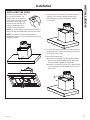
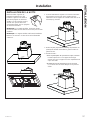
Installation Preparation
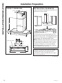
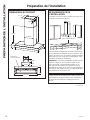
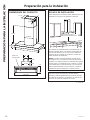
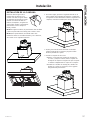
INSTALLATION CLEARANCES
These vent hoods are designed to be installed onto
a wall with no above cabinets.
The vent hood must be installed between the 24”
required minimum and 36” recommended maximum
above the cooking surface. For supplied duct cover
ceiling heights, see Installation Height Table.
NOTE: Installation height should be measured from
the cooking surface to the lowest part of the hood.
The hood must be installed onto a wall. It can be
vented to the outdoors, or it can be installed for
recirculating operation. For recirculation operation,
see Recirculation Install Planning.
PRODUCT DIMENSIONS
INSTALLATION PREPARATION
26-5/8Ǝ min. - 50-7/8Ǝ max.
12-1/4Ǝ
2-3/4Ǝ
4-5/8Ǝ
13-13/16Ǝ
25-3/4Ǝ
30ƎRUƎ
20Ǝ
24” Required Min.
36” Recommended Max.
20Ǝ
30ƎRUƎ
Filter Cover Panel
12-1/8Ǝ
8Ǝ
6-15/16Ǝ
10-5/8Ǝ
Installation instructions, describing the intended
mounting and wiring of the range hood cord
connection kit, shall be provided with each range
hood cord connection kit.
1" = 2.5 cm

49-2000896 Rev. 1 11
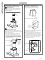
INSTALLATION PREPARATION
Installation Preparation
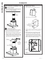
PLAN THE INSTALLATION
CAUTION
To reduce risk of fire and to
properly exhaust air, be sure to duct the air outside.
Do not vent exhaust air into spaces within walls or
ceilings or into attics, crawl spaces, or garages.
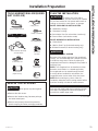
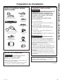
PARTS SUPPLIED FOR INSTALLATION
Ŷ 1 Hardware Package
Ŷ 1 Literature Package
Ŷ Recirculation Duct (for recirculation install only)
Ŷ Charcoal filters (recirculation mode)
PARTS NEEDED FOR INSTALLATION
Ŷ 1 Strain Relief
Ŷ 1 Wall or Roof Cap (for ducted venting only)
Ŷ All Metal Ductwork (for ducted venting only)
WARNING
PERSONAL INJURY HAZARD
Because of the weight and size of the rangehood
canopy. It is recommended that 2 people are used
to install the range hood. Failure to properly lift
rangehood could result in damage to the product or
personal injury.
NOTE: This rangehood can be installed as either
ducted or recirculation. In a ducted application,
this rangehood can be vented through the wall
or ceiling. When installed for recirculation, the
rangehood vents out the sides of the duct cover.
NOTE: Before making any cuts or holes for
installation, determine which venting method will be
used and carefully calculate all measurements.
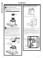
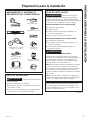
TOOLS AND MATERIALS REQUIRED
(NOT SUPPLIED)
REMOVE THE PACKAGING
CAUTION
Wear gloves to protect against
sharp edges.
Ŷ Remove the duct covers.
Ŷ Remove the hardware bag, literature package
and other boxed parts.
Ŷ Remove and properly discard the protective
plastic wrapping and other packaging materials.
Wire cutter/stripper
Level
Aluminized
duct tape
Safety glasses
Phillips screwdriver
Strain relief for
junction box
Electric drill with #2 Phillips
and 1/8" drill bits
UL listed wire nuts
8" round duct
(length will vary)
Pencil and tape measure
Gloves
Use only with range hood cord connection kits that
have been investigated and found acceptable for
use with this model range hood.
1" = 2.5 cm

12 49-2000896 Rev. 1
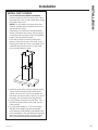
Installation Preparation
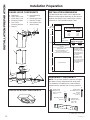
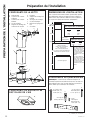
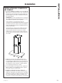
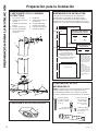
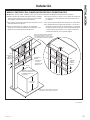
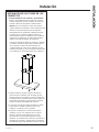
INSTALLATION DIMENSIONS
The Wall Hoods duct covers can be adjusted for
different ceiling heights depending on the distance
between the bottom of the hood and the cooktop
(distance X). See Installation Height Table.
RANGE HOOD COMPONENTS
RECIRCULATION COMPONENTS
INSTALLATION PREPARATION
A. Wall Hood
B. Upper Duct Cover
C. Lower Duct Cover
D. Mounting Screws
E. Duct Cover
Mounting Bracket
F. Damper
G. Hood Mounting
Bracket
H. Mounting Anchors
J. Machine Screws
K. Recirculation Box
L. Wood Screws
7/8Ǝ min
25-1/8Ǝ max
25-3/4Ǝ
2-3/4Ǝ
36”
X
X = Distance From Hood To
Cooktop
(Varies depending on installation)
Required Min - 24”,
Recommended Max - 36”
Also consult cooktop
manufacturer’s recommendation
For higher ceiling
installations up to
12', use the 12' High
Ceiling Duct Cover
kit (UX12DC93) for
your model.
For higher ceiling
installations up to
14', use the 14' High
Ceiling Duct Cover
kit (UX14DC93) for
your model.
Typical Range
Upper Duct
Cover
Lower
Duct Cover
Hood Body
Required Min & Recommended
Max Ceiling Height Examples
X = 24" X = 36"
Min Min
7' 6" 9' 6"
Max Max
8' 6" 10' 5"
Required Min Ceiling
Height for Recirculation
X = 24" X = 36"
Min Min
7' 10" 8' 10"
K
A
D
F
J
E
D
J
K
J
H
H
G
L
C
B
J
J
J
H
D
L
HARDWARE COMPONENTS
NOTE: The chimney extension replaces the upper
and lower chimney shipped with the range hood.
The hardware included with the hood should be
saved and also used with the chimney extension.
E
L
H
J
Phillips Head
Wood Screw
3/16" x 1-15/16"
(QTY: 4)
Phillips Head
Machine Screw
1/8" x 3/8"
(QTY: 14)
Phillips Head
Mounting Anchors
Screws
3/16" x 1-1/2"
(QTY: 6)
Mounting Anchors
(QTY: 6)
D
1' = 0.3 m, 1" = 2.5 cm

49-2000896 Rev. 1 13
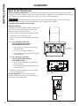
INSTALLATION PREPARATION
Installation Preparation
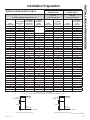
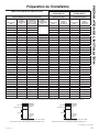
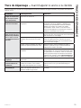
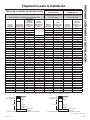
INSTALLATION HEIGHT TABLE
(UX12DC9SLSS or
UX12DC9BJTS)
(UX14DC9SLSS or
UX14DC9BJTS)
Installation Height with Supplied Duct Covers
Optional High Ceiling Duct Cover
up to 12 ft.
(not included with unit)
Optional High Ceiling Duct Cover
up to 14 ft.
(not included with unit)
Ceiling
Height (ft./in.)
Possible Vented
Install Height
(in.)
Possible Vented
Install Height
(Recirculation
vented Holes
Hidden) (in.)
Possible
Recirculation
Install
Height (in.)
Ceiling
Height (ft./in.)
Vented and
Recirculation
Height (in.)
Ceiling
Height (in.)
Vented and
Recirculation
Install
Height (in.)
7' 6" 24 24 9' 3" 24 12' 24-36
7' 7" 24-25 24-25 9' 4" 24-25 12' 1" 24-36
7' 8" 24-26 24-26 9' 5" 24-26 12' 2" 24-36
7' 9" 24-27 24-27 9' 6" 24-27 12' 3" 24-36
7' 10" 24-28 24-28 24 9' 7" 24-28 12' 4" 24-36
7' 11" 24-29 24-29 24-25 9' 8" 24-29 12' 5" 24-36
8' 24-30 24-30 24-26 9' 9" 24-30 12' 6" 24-36
8' 1" 24-31 24-31 24-27 9' 10" 24-31 12' 7" 24-36
8' 2" 24-32 24-32 24-28 9' 11" 24-32 12' 8" 24-36
8' 3" 24-33 24-33 24-29 10' 24-33 12' 9" 24-36
8' 4" 24-34 24-34 24-30 10' 1" 24-34 12' 10" 24-36
8' 5" 24-35 24-35 24-31 10' 2" 24-35 12' 11" 24-36
8' 6" 24-36 24-36 24-32 10' 3" 24-36 13' 24-36
8' 7" 24-36 24-36 24-33 10' 4" 24-36 13' 1" 25-36
8' 8" 24-36 24-36 24-34 10'5"-11'3" 24-36 13' 2" 26-36
8' 9" 24-36 24-36 24-35 11' 4" 24-36 13' 3" 27-36
8' 10" 24-36 24-36 24-36 11'5" 24-36 13' 4" 28-36
8' 11" 24-36 24-36 24-36 11'6" 24-36 13' 5" 29-36
9' 24-36 24-36 24-36 11'7" 24-36 13' 6" 30-36
9' 1" 24-36 24-36 24-36 11'8" 25-36 13' 7" 31-36
9' 2" 24-36 25-36 24-36 11'9" 26-36 13' 8" 32-36
9' 3" 24-36 26-36 24-36 11'10" 27-36 13' 9" 33-36
9' 4" 24-36 27-36 24-36 11' 11" 28-36 13' 10" 34-36
9' 5" 24-36 28-36 24-36 12' 29-36 13' 11" 35-36
9' 6" 25-36 29-36 25-36 14' 36
9' 7" 26-36 30-36 26-36
9' 8" 27-36 31-36 27-36
9' 9" 28-36 32-36 28-36
9' 10" 29-36 33-36 29-36
9' 11" 30-36 34-36 30-36
10' 31-36 35-36 31-36
10' 1" 32-36 36 32-36
10' 2" 33-36 33-36
10' 3" 34-36 34-36
10' 4" 35-36 35-36
10' 5" 36 36
*Based on a 36" electric range height.
For gas range, start chart at 92" and subtract 2" for the maximum install height for each block.
7/8Ǝ min
29-7/16Ǝ max
7/8Ǝ min
46-1/4Ǝ max
46-7/8" 46-7/8"
12" High Ceiling Duct Cover Kit 14" High Ceiling Duct Cover Kit
Upper
Duct Cover
Upper
Duct Cover
Lower
Duct Cover
Lower
Duct Cover
Hood Body Hood Body
1' = 0.3 m, 1" = 2.5 cm

14 49-2000896 Rev. 1
INSTALLATION PREPARATION
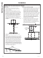
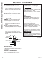
ADVANCE PLANNING
Duct Install Planning
Ŷ This hood is designed to be vented vertically
through the ceiling. Use an 8" round duct. Use
locally supplied elbows to vent horizontally
through the rear wall.
Ŷ Use metal ductwork only.
Ŷ Determine the exact location of the vent hood.
Ŷ Plan the route for venting exhaust to the
outdoors. To maximize the ventilation
performance of the vent system:
1. Minimize the duct run length and number of
transitions and elbows.
2. Maintain a constant duct size.
3. Seal all joints with duct tape to prevent any leaks.
NOTE: Flexible vent is not recommended. Flexible
vent creates back pressure and air turbulence that
greatly reduces performance.
Ŷ Maximum equivalent duct length for 100 CFM:
150 foot for vent hoods.
Ŷ Install a wall cap or roof cap with damper at the
exterior opening. Purchase the wall or roof cap
and any transition and length of duct needed in
advance.
Ŷ When applicable, install any makeup (replacement)
air system in accordance with local building code
requirements. Use makeup air kit JXMUA8.
Vent system can terminate either through the roof
RUWKHZDOO7RYHQWWKURXJKDZDOODHOERZLV
needed and installed immediately above the hood.
Recirculation Install Planning
A recirculation duct (included) and charcoal
filter (included) are necessary for recirculation
installation.
Power Supply Planning
The location of the power supply connection is called
out in the Installing The Hood Bracket Mount section.
POWER SUPPLY
IMPORTANT – (Please read carefully)
WARNING
FOR PERSONAL SAFETY, THIS APPLIANCE
MUST BE PROPERLY GROUNDED.
Remove house fuse or open circuit breaker before
beginning installation.
Do not use an extension cord or adapter plug with
this appliance. Follow National Electrical Codes or
prevailing local codes and ordinances.
Electrical supply
These vent hoods must be supplied with 120V,
60Hz, and connected to an individual, properly
grounded branch circuit, and protected by a 15 or
20 amp circuit breaker or time delay fuse.
Ŷ Wiring must be 2 wire with ground.
Ŷ If the electrical supply does not meet the above
requirements, call a licensed electrician before
proceeding.
Ŷ Route house wiring as close to the installation
location as possible in the ceiling or wall.
Ŷ Connect the wiring to the house wiring in
accordance with local codes.
Grounding instructions
The grounding conductor must be connected to
a ground metal, permanent wiring system, or an
equipment-grounding terminal or lead on the hood.
WARNING
The improper connection of the
equipment-grounding conductor can result in a risk
of electric shock. Check with a qualified electrician
or service representative if you are in doubt whether
the appliance is properly grounded.
Installation Preparation
Roof Cap
Round Duct
Wall Cap
Add Insulation
and/or Caulk
Add Insulation
and/or Caulk
Add tape to joint
Hood
1" = 2.5 cm

49-2000896 Rev. 1 15
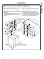
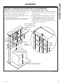
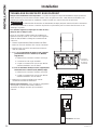
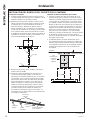
NEW CONSTRUCTION, PRE-PLANNING, OR REMODELING
NOTE: For existing construction, skip to the section, Installing The Hood Bracket Mount.
Ŷ Install horizontal wood supports between 2 wall
studs that align with the vertical mounting height
locations shown in the illustration.
Ŷ The horizontal supports must be flush with the room
side studs.
Ŷ For ducted installation, the hole for the duct in the
ceiling must be centered 5" away from the finished
rear wall.
Ŷ The bottom support aligns with the hood mounting
bracket. This height depends on the desired height
of the hood.
Ŷ The top support must be flush with the ceiling.
Ŷ The electrical wiring can be located 5-1/2” to the left
or right (junction box is on the left) of the centerline.
Must remain 7/16” above the back panel and 5” from
the ceiling, refer to illustration on next page.
INSTALLATION
Installation
Acceptable
area for
electrical
wiring
Acceptable
area for
electrical
wiring
14-3/8"
14-3/8"
5"
5"
11"
11"
See the Installation
Height Table for possible
installation heights.
24-36" + 1-1/8"
Wood Supports
• 36" minimum
width centered
• 4" height
From the lower left corner of
the gray shaded area, it is
recommended to have at least
20" of house electrical wiring.
* 36” or 38” Range
* Typical electrical range is 36"
and typical gas range is 38"
1" = 2.5 cm

16 49-2000896 Rev. 1
Installation
INSTALLATION
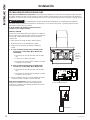
INSTALLING THE HOOD BRACKET MOUNT
Hood Body
1. Put a protective covering over the surface
below the location of the hood to protect from
dirt and/or damage.
2. Determine and mark the centerline (C) on the
wall (draw line up to the ceiling) where the range
hood will be installed. Based on the ceiling height,
determine the distance between 24” required
min, 36” recommended max (X) needed between
the cooking surface (B) and the bottom of the
hood. Draw a horizontal line at X. Align the install
template so that the bottom of the template is
centered and is level with the horizontal line drawn
at height X.
3. Find the stud locations and mark them on the
template.
4. Place the hood mounting bracket (G) on its outline
on the template. Mark at least one wood screw (L)
location that is on a stud. If another stud cannot be
found, mark at least two other screw locations for
mounting anchors, one on each side of the wood
screw (L). Remove the bracket from the wall and
install the mounting anchors (H). Place the hood
mounting bracket (G) back on the wall and mount it
with the wood screws (L) and mounting screws (D)
as needed. It is recommended to create a pilot hole
in the studs for wood screws (L).
Duct Covers and Power Supply
1. Place the duct cover bracket (E) on the wall so that
its edge is against the ceiling and level, making
sure the slots are in direct contact with the wall.
Align the center notches of the bracket and the
centerline. Mark the location of the screw holes
furthest apart from the center line if possible. If one
of the screw holes aligns with a stud, then a wood
screw will be used for that location. For the other
hole or if there are no studs, install 2 mounting
anchors (H). Place the duct cover bracket (E)
on the wall and install with wood screws (L) and
mounting screws (D) as needed.
2. The house electrical wiring must fall in the gray
shaded area shown below. From the lower left
corner of the shaded area, a minimum of 20” of
house electrical wiring is recommended to reach
the electrical junction box on the hood.
C
B
1-1/8"
X
24 to 36"
Hood Mounting Bracket
Mounting
Screw
Mounting
Screw
Wood Screw
Mounting
Anchors
Ǝ%HORZ&HLOLQJ
C
Ceiling
Ǝ
16-7/8"
Acceptable
area for house
electrical
wiring
1" = 2.5 cm

49-2000896 Rev. 1 17
INSTALLATION
INSTALLING THE HOOD
Remove the grease filters from
the unit and set aside. The
grease filters are removed by
pressing the handle in the front
of the filter. When replacing,
make sure that the filters are
properly positioned with the
handles in front and visible.
NOTE: On some models, the front panel covers the
filters and must be pulled down to access the filters.
NOTE: This bracket must be removed prior to
installation. Remove 2 front and 2 bottom screws per
illustration bellow.
1. Securely press the damper on top of the exhaust
opening. Check that the damper opens freely.
Attach damper to hood using machine screws
(J) provided.
2. Remove and properly discard the protective plastic
wrapping from the hood and grease filter. Remove
the template off the wall.
3. Mount the Range Hood:
Ŷ Using 2 or more people, lift the range hood and
place on the hood mounting bracket. Make sure
the bracket fully engages the hood body.
Ŷ Install the 2 mounting screws (D) or wood screws
(L) as needed into the designated holes on the
back panel.
Installation

18 49-2000896 Rev. 1
Installation
INSTALLATION
ELECTRICAL CONNECTION
1. Remove the electrical junction box cover.
2. Remove the electrical box knockout.
3. Feed the Power Supply Cable through the hole
and secure with a strain relief.
4. Attach the white lead of the power supply (A) to
the white lead of the range hood (D) with a wire
nut. Attach the black lead of the power supply (B)
to the black lead of the range hood (C) with a wire
nut. Connect the house ground wire under the
green grounding screw (E).
5. Reattach the electrical junction box cover.
INSTALLING THE HOOD (Cont.)
A
Vented Installations
Connect the house ducting to the damper on the
hood body. Seal all connections with duct tape
(Do not use screws).
B
Recirculation (Non-vented)
NOTE: A recirculation box, a charcoal filter, and a
bracket are included with the hood and are necessary
for recirculation installation.
1. Attach the recirculation box to the duct over
mounting bracket with 4 machine screws (J).
2.
Connect the ducting from the exhaust outlet on
the hood to the recirculation box. Use duct tape
to seal the connections on the recirculation box
and the exhaust outlet.
House Wiring
A
E
D
C
B
Hood Wiring
Electrical Box
Knockout with
Strain Relief
Ceiling
House
Ducting
Recirculation Box
Duct Cover
Mounting
Bracket
Use tape
(Do not use screws)

49-2000896 Rev. 1 19
INSTALL DUCT COVERS
1. For ducted and recirculation installation:
Remove protective film from duct covers. Place
the upper duct cover so that it slides down inside
of the lower duct cover.
NOTE: For recirculation, the upper duct cover
must be installed with the exhaust vents on the
top towards the ceiling.
Depending on the amount of overlap between
the top and bottom duct covers, the top may be
reversed to hide vent holes. Refer to Installation
Height Table for possible heights.
Place the set of duct covers by sitting them
down to fit securely on top of the hood. Finish
attaching the lower duct cover to the body of the
hood with two machine screws (J) that screw
from up underneath the hood.
2. Install the upper duct cover by carefully raising
it up to avoid scratching until it reaches the
ceiling. Push the duct cover flush against the
wall, then use two machine screws (J) to mount
the upper duct to the duct mounting bracket.
3. If recirculating, install the charcoal filters. Then
reinstall the grease filters to the hood, see the
Filters section.
4. Turn the power supply on. Turn on the blower
and light. If the range hood does not operate,
check that the circuit breaker is not tripped or the
house fuse blown. If the unit still does not operate,
disconnect the power supply and check that the
wiring connections have been made properly.
Installation
INSTALLATION

20 49-2000896 Rev. 1
Installation
INSTALLATION
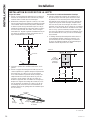
MAKE UP AIR TECHNOLOGY
Note to Installers and Inspectors: This product comes equipped with a simple installation feature that limits
maximum CFM levels in order to comply with certain local codes or regulations. This installation method may not
be necessary for all installations, please refer to your local codes for further guidelines.
CAUTION
Hood must be disconnected from main power prior performing the conversion instructions
listed below. Failure to do so could result in personal injury or damage to the product.
To modify unit (if needed for local codes):
390CFM or 290CFM
By design, the maximum blower speed is greater than
400 CFM. For local codes requiring reduced CFM,
modify the wiring as described below:
1. Open the filter cover panel and remove the filters.
2. Remove the control board box cover.
3. Locate the motor harness plugged into the control
board.
4. A -
For a maximum of 390 CFM
Unit can operate with 4 speeds
(Low, Medium, High, Boost).
1. Disconnect the connector of the blue wire
from the red wire.
2. Connect the 2 red wires together.
3. Cut off the blue unused connector and crimp
the end if desired.
B -
For a maximum of 290 CFM
Unit can operate with 3 speeds
(Low, Medium, High).
1. Disconnect the connector of the blue wire
from the red wire.
2. Cut off the blue unused connector and crimp
the end if desired.
5. Reattach the control board box cover and install
Filters, see Filters section.
Note to Inspectors: To verify this product was
installed in either configuration, check motor wiring
connections as described above.
Motor Harness Connector
Blue
Red
Red
Motor Harness
Control Board
Box Cover
La page est en cours de chargement...
La page est en cours de chargement...
La page est en cours de chargement...
La page est en cours de chargement...
La page est en cours de chargement...
La page est en cours de chargement...
La page est en cours de chargement...
La page est en cours de chargement...
La page est en cours de chargement...
La page est en cours de chargement...
La page est en cours de chargement...
La page est en cours de chargement...
La page est en cours de chargement...
La page est en cours de chargement...
La page est en cours de chargement...
La page est en cours de chargement...
La page est en cours de chargement...
La page est en cours de chargement...
La page est en cours de chargement...
La page est en cours de chargement...
La page est en cours de chargement...
La page est en cours de chargement...
La page est en cours de chargement...
La page est en cours de chargement...
La page est en cours de chargement...
La page est en cours de chargement...
La page est en cours de chargement...
La page est en cours de chargement...
La page est en cours de chargement...
La page est en cours de chargement...
La page est en cours de chargement...
La page est en cours de chargement...
La page est en cours de chargement...
La page est en cours de chargement...
La page est en cours de chargement...
La page est en cours de chargement...
La page est en cours de chargement...
La page est en cours de chargement...
La page est en cours de chargement...
La page est en cours de chargement...
La page est en cours de chargement...
La page est en cours de chargement...
La page est en cours de chargement...
La page est en cours de chargement...
La page est en cours de chargement...
La page est en cours de chargement...
La page est en cours de chargement...
La page est en cours de chargement...
La page est en cours de chargement...
La page est en cours de chargement...
La page est en cours de chargement...
La page est en cours de chargement...
-
 1
1
-
 2
2
-
 3
3
-
 4
4
-
 5
5
-
 6
6
-
 7
7
-
 8
8
-
 9
9
-
 10
10
-
 11
11
-
 12
12
-
 13
13
-
 14
14
-
 15
15
-
 16
16
-
 17
17
-
 18
18
-
 19
19
-
 20
20
-
 21
21
-
 22
22
-
 23
23
-
 24
24
-
 25
25
-
 26
26
-
 27
27
-
 28
28
-
 29
29
-
 30
30
-
 31
31
-
 32
32
-
 33
33
-
 34
34
-
 35
35
-
 36
36
-
 37
37
-
 38
38
-
 39
39
-
 40
40
-
 41
41
-
 42
42
-
 43
43
-
 44
44
-
 45
45
-
 46
46
-
 47
47
-
 48
48
-
 49
49
-
 50
50
-
 51
51
-
 52
52
-
 53
53
-
 54
54
-
 55
55
-
 56
56
-
 57
57
-
 58
58
-
 59
59
-
 60
60
-
 61
61
-
 62
62
-
 63
63
-
 64
64
-
 65
65
-
 66
66
-
 67
67
-
 68
68
-
 69
69
-
 70
70
-
 71
71
-
 72
72


GE UVW9301BLTS Le manuel du propriétaire
- Catégorie
- Hottes
- Taper
- Le manuel du propriétaire
- Ce manuel convient également à
dans d''autres langues
- English: GE UVW9301BLTS Owner's manual
- español: GE UVW9301BLTS El manual del propietario
Documents connexes
Autres documents
-
Monogram UVW9361BLTS Mode d'emploi
-
-
-
GE Appliances UVC7300 Le manuel du propriétaire
-
GE Appliances UVC9300SLSS Le manuel du propriétaire
-
Faber OSTR30SS400 Le manuel du propriétaire
-
-
GE Profile UVC9480SLSS Le manuel du propriétaire
-
Bosch DRZ7007UC(00) Guide d'installation