
SANITATION
TOILET
REVISION B | Form No. 600347268.000 04/2020 | ©2020 Dometic Corporation
WARNING
Cancer and Reproductive Harm
www.P65Warnings.ca.gov
MasterFlush
®
7600 Series
EN
Macerator Toilet
Installation and Operation Manual ........2
FR
Cuvette de toilette à pompe dilacératrice
Manuel d’installation et d’utilisation .....14

2
EN
Contents MasterFlush 7600 Series Toilet
1 Explanation of Symbols and Safety
Instructions ............................ 2
1.1 Recognize Safety Information .............2
1.2 Understand Signal Words ................2
1.3 Supplemental Directives .................2
1.4 General Safety Messages ................3
2 General Information ..................... 3
2.1 Model Identification ....................4
2.2 Component Locations. . . . . . . . . . . . . . . . . . .4
3 Intended Use ........................... 5
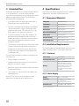
4 Specifications .......................... 5
4.1 Component Materials ...................5
4.2 Installation Requirements ................5
4.3 Toilet Dimensions ......................6
4.4 Rough-In Dimensions ...................6
5 Wiring Diagram ......................... 7
6 Installation ............................. 7
6.1 Preparing to Install the Toilet .............7
6.2 Removing an Existing Toilet ..............7
6.3 Installing the Toilet .....................8
7 Operation ............................. 10
7.1 Adding Water to the Bowl ...............10
7.2 Flushing the Toilet ..................... 11
7.3 Changing the Flush Settings ............. 11
7.4 Understanding the Full Tank Indicator ..... 11
8 Maintenance ...........................11
8.1 Cleaning ............................ 11
8.2 Routine Maintenance ..................12
8.3 Winterizing ..........................12
9 Troubleshooting ....................... 13
10 Disposal .............................. 13
11 Warranty Information ................... 13
Contents
Service Center & Dealer Locations
Visit: www.dometic.com
Read these instructions carefully. These instructions
MUST stay with this product.
1 Explanation of Symbols and
Safety Instructions
This manual has safety information and instructions to
help you eliminate or reduce the risk of accidents and
injuries.
1.1 Recognize Safety Information
This is the safety alert symbol. It is used to alert
you to potential physical injury hazards. Obey all
safety messages that follow this symbol to avoid
possible injury or death.
1.2 Understand Signal Words
A signal word will identify safety messages and property
damage messages, and also will indicate the degree or
level of hazard seriousness.
DANGER!
Indicates a hazardous situation that, if not avoided,
will result in death or serious injury.
WARNING
Indicates a hazardous situation that, if not avoided,
could result in death or serious injury.
CAUTION
Indicates a hazardous situation that, if not avoided,
could result in minor or moderate injury.
NOTICE: Used to address practices not related to
physical injury.
I
Indicates additional information that is not related
to physical injury.
1.3 Supplemental Directives
To reduce the risk of accidents and injuries, please
observe the following directives before proceeding to
install, operate, or service this appliance:
• Read and follow all safety information and
instructions.

3
EN
MasterFlush 7600 Series Toilet General Information
• Read and understand these instructions before
installing,operating, or servicing this product.
• The installation must comply with all applicable local
or national codes, including the latest edition of the
following standards:
U.S.A.
– ANSI/NFPA70, National Electrical Code (NEC)
– ANSI/NFPA 1192, Recreational Vehicles Code
– ANSI Z21.57, Recreational Vehicles Code
Canada
– CSA C22.1, Parts l & ll, Canadian Electrical Code
– CSA Z240 RV Series, Recreational Vehicles
1.4 General Safety Messages
WARNING: ELECTRICAL SHOCK, FIRE, AND/
OR EXPLOSION HAZARD. Failure to obey the
following warnings could result in death or
serious injury.
• Turn the power off before performing any electrical
installation or maintenance activities.
• Use care when diagnosing and/or adjusting
components on a powered unit.
• Use only Dometic replacement parts and
components that are specifically approved for use
with the appliance.
• Avoid improper installation, adjustment, alterations,
service, or maintenance of the appliance. Service and
maintenance must be done by a qualified service
person only.
• Do not modify this product in any way. Modification
can be extremely hazardous.
• Do not overfill the holding tank. To reduce this
possibility, use the full-tank shut-down circuitry in
the toilet’s electronic control module. An optional
Dometic tank monitor system can generate a full-
tank signal and disable flushing until the holding
tank is emptied. Overfilling the holding tank can
cause serious damage to the sanitation system, such
as rupturing the holding tank and releasing tank
contents into the motorhome.
2 General Information
This section provides information on the tooling and
parts for the MasterFlush
®
7600 Series toilet.
I
The images used in this document are for reference
purposes only. Components and component
locations may vary according to specific product
models. Measurements may vary ±0.38 in. (10 mm).
Included Kits Quantity
Mounting Hardware Kit
(Floor Flange or Remote)
1
MasterFlush 7600 Series Toilet
1
Recommended Tools
Pliers or Adjustable Wrench Drill
7/16 in. (11 mm) Wrench Electrical Connection
Tools
Optional Parts
The MasterFlush 7600 Series toilet can be connected
to one of several Dometic holding tank monitoring
systems to offer accurate, continuous tracking of tank
capacity. Contact the Dometic Customer Support
Center or www.dometic.com for more information.

4
EN
General Information MasterFlush 7600 Series Toilet
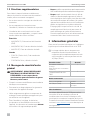
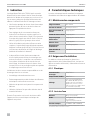
2.1 Model Identification
The toilet model identification label is located on the
toilet base under the water valve. Have this information
ready before contacting Dometic for service.
Loreasm
Loreasam
Model :
Item :
123456789
PNC :
123456789
Serial :
123456789
SO 1234
1 Model Identification Example
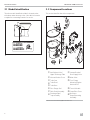
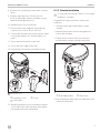
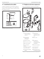
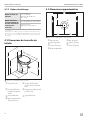
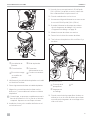
2.2 Component Locations
This section identifies the toilet components.
e
w
o
r
t
u
a
g
f
f
d
s
y
i
q
2 Component Locations
q
Anti-Siphon Valve/
Upper Discharge Tube
o
Vacuum Breaker/
Bowl Supply Hose
w
Vacuum Breaker Cover
a
Water Valve
e
Toilet Seat
s
Floor Flange
Mounting Option
Hardware Kit
1
r
Toilet Bowl
t
Toilet Base
y
Floor Flange Seal
d
Control Module
u
Flush Pedal Assembly
f
Pump/Base Cover
i
Discharge Pipe/
Trap Assembly
g
Macerator
Pump/Mounting
Assembly
1
Not shown: Remote Mounting Option Hardware Kit.

5
EN
MasterFlush 7600 Series Toilet Intended Use
3 Intended Use
The MasterFlush 7600 Series toilet (hereinaer referred
to as “MasterFlush”) is an electric-flush toilet that
macerates waste and pumps it to a holding tank or other
effluent storage/disposal system. The MasterFlush
provides the following benefits:
• A convenient electronic flush feature adds water or
flushes by pressing on the flush pedal.
• Two water consumption flush settings offer flexibility.
The normal flush uses 0.8 gal (3 L) and adds water
to the bowl aer a flush. The dry bowl uses 0.2 gal
(0.8L) and does not add water to the bowl.
• A versatile installation location offers flexibility. The
powerful macerator pump allows the toilet to be
located up to 40 (12.2 m) away from the holding
tank or other discharge line destination (remote
installation method).
• The automatic full-tank shut-down safety feature helps
avoid motorhome damage. When connected to a
holding tank level indication system, the toilet will
not flush when the holding tank is full and prevents
overfilling the tank.
The manufacturer accepts no liability for damage in the
following cases:
• Faulty assembly or connection
• Damage to the product resulting from mechanical
influences and excess voltage
• Alterations to the product without express permission
from the manufacturer
• Use for purposes other than those described in the
operating manual
Dometic Corporation reserves the right to modify
appearances and specifications without notice.
4 Specifications
The following section provides the materials, installation
requirements, and toilet rough-in dimensions.
4.1 Component Materials
Toilet Seat
Enameled Wood
Toilet Bowl
Vitreous Ceramic
Toilet Base
Polypropylene
Flush Pedal
Polypropylene
Macerator Pump Body
Glass-Filled Polypropylene
Water Valve
Polypropylene
Vacuum Breaker
ABS/Polypropylene
Floor Flange Seal
Nitrile Rubber, Foam
4.2 Installation Requirements
The following tables list the MasterFlush electrical, water
supply, discharge options, and rough-in dimensions.
4.2.1 Electrical
Power draw 15 A/12 VDC
Circuit breaker/fuse 20 A/12 VDC
Wiring
Refer to ANSI/RVIA LV and
NFPA 70/NEC Standards
for the recommended wire
gauge (USA). Refer to CEC
I and II Standards for the
recommended wire gauge
(Canada).
4.2.3 Water Supply
Fitting 0.5 in. (13 mm) NPT
Flow Rate 3–5 gpm (11.4–18.9 lpm)
recommended*
2 gpm (9.5 lpm) minimum
Static Pressure 30–100 PSI (207–690 kPa)
*A water supply that exceeds 5 gpm (18.9 lpm) may require a flow
restrictor at the toilet inlet.

6
EN
Specifications MasterFlush 7600 Series Toilet
4.2.4 Discharge Options
Floor Flange Option
Floor flange
3 in. (76 mm) ID;
0.25– 0.4 in. (6–11 mm) thick
Remote Option
(not mounted on the
flange directly above
the waste tank)
Sanitation hose size
1.5 in. (38 mm) or 1 in. (25 mm) ID
Horizontal hose run
40 (12.2 m) maximum**
**Check for an adequate discharge flow if the installation nears this distance.
Refer to ANSI 1192 and Z240 RV Series standards, where applicable, for
additional RV toilet installation guidelines. Specifications are subject to
change without notice.
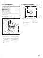
4.3 Toilet Dimensions
e
q
u
y
w
t
r
3 Toilet Dimensions and Clearances
q
15 in. (381 mm)
t
14.8 in. (375 mm)
back to front of base
w
33.9 in. (860 mm)
seat lid up
y
18.4 in. (467 mm)
seat height
e
20 in. (508 mm)
u
19 in. (483 mm)
r
10 in. (254 mm)
rough-in
4.4 Rough-In Dimensions
e
r
w
q
t
y
u
4 Rough-In Dimensions and Clearances
q
Back wall
t
Right wall
w
Le wall
y
11 in. (279 mm)
e
10 in. (254 mm)
u
11 in. (279 mm)
r
Floor flange

7
EN
MasterFlush 7600 Series Toilet Wiring Diagram
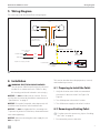
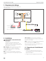
5 Wiring Diagram
This section provides the MasterFlush wiring diagram.
Water Valve
Circuit Board
with Internal Fuse
Motor
Full Tank Float
OPTIONAL (recommended)
DTM01 Panel Option
+12 VDC Input
Input Power Supply -12 VDC
+12 VDC Input
- VDC Input
Fuse or Breaker
0.5 AMP
Fuse or Breaker
25 AMP
Toilet
Brown
Brown
Orange
Black
Black
Red
Yellow
1 2 7
3 4 5 6
Black
Red
Blue
5 Wiring Diagram
6 Installation
WARNING: ELECTRICAL SHOCK HAZARD.
Turn the power off before performing any electrical
installation or maintenance work. Failure to obey
this warning could result in death or serious injury.
NOTICE: Do not install the toilet in a shower. Be sure
to follow the recommended installation requirements in
“Specifications” on page5.
NOTICE: Be sure the foot pedal, when depressed, will
touch the same flat surface as the installed toilet.
NOTICE: Do not over-tighten the floor mounting nuts.
To prevent any distortion of the base, alternate between
sides when tightening.
NOTICE: When reconnecting the water supply line, do
not over tighten.
This section describes the toilet preparation, removal,
and installation processes.
6.1 Preparing to Install the Toilet
1. Verify the location meets all the recommended
clearances for the new model. See Figure3 &
Figure4.
2. Turn off the power to the toilet’s location.
3. Turn off the water supply to the toilet’s location.
6.2 Removing an Existing Toilet
I
If a toilet removal is unnecessary, skip to “Installing
the Toilet” on page8.
1. Disconnect the power to the toilet.

8
EN
Installation MasterFlush 7600 Series Toilet
2. Disconnect and drain the water supply line.
3. Remove the toilet hold-down bolts and screws.
4. Remove the toilet from the floor.
5. Remove and dispose of the old floor flange seal, the
hold-down bolts, and any removal debris.
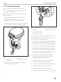
6.3 Installing the Toilet
This section describes the two toilet installation options.
6.3.1 Floor Flange Installation
I
To install the toilet farther from the holding tank,
skip to “Remote Installation” on page9.
NOTICE: When lowering the toilet onto the floor flange,
the toilet must align so that the outlet at the base fits
inside the floor flange outlet hole.
NOTICE: The floor flange must be secured to the floor
with a minimum of four screws (eight is recommended).
Complete these steps to perform a floor flange toilet
installation:
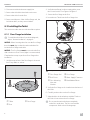
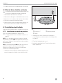
1. Verify the top surface of the floor flange is clean and
free of any debris or sealant.
q
w
e
6 Installing the T-Bolts
q
T-Bolts
e
Floor Flange
w
Slots
2. Verify the new flange’s toilet mounting holes are at
the correct location. See Figure4 & Figure6.
3. Secure the floor flange to the floor.
4. Insert the two T-bolts into the floor flange slots.
q
e
r
t
w
y
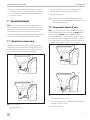
7 Installing the Floor Flange
q
Floor Flange Seal
r
Floor Flange
w
Bolt Covers
t
Water Supply Connector
e
Floor Mounting
Nuts and
Washers
y
Black Rubber Elbow
5. Verify the floor flange seal is installed onto the base of
the toilet.
6. Carefully set the toilet over the floor flange.
7. Align the holes in the toilet base with the T-bolts as
the toilet is lowered onto the floor flange.
I
Do not rest the entire toilet base completely
on the floor at this time. The floor seal must be
compressed. Refer to the following steps.

9
EN
MasterFlush 7600 Series Toilet Installation
8. Install the floor mounting nuts and washers onto the
T-bolts.
9. Carefully torque the nuts to 30–40 in. lb (3.4–
4.5N·m). When tight, the base should be securely
attached and flat against the floor.
10. Attach the bolt covers onto the nuts.
11. Reconnect the water supply line and torque the
connection to 30–40 in. lb (3.4–4.5 N·m).
12. Connect the electrical power to the toilet according
to the wiring diagram. See “Wiring Diagram” on
page7.
13. Turn on the electrical power to the toilet.
14. Turn on the water supply to the toilet.
15. Flush the toilet several times and check for leaks.
q
e
w
8 Attaching the Cover
q
Pump/Base Cover
e
Screws
w
Locking Tabs
16. Attach the pump/base cover to the base using the
screws at the sides of the toilet base and using the
locking tabs at the sides and the back.
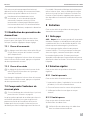
6.3.2 Remote Installation
I
To install with a floor flange, return to “Floor Flange
Installation” on page8.
Complete these steps to perform a remote toilet
installation.
1. Place the toilet in the location where it will be
installed.
2. Mark the fastener hole locations through the two
holes in the toilet base.
3. Drill pilot holes for the two hex screw fasteners
provided in the remote mounting hardware kit.
q
w
9 Removing the Black Elbow
q
Black Rubber Elbow
w
Check Valve
4. Remove the black rubber elbow from the check valve
at the back of the toilet.

10
EN
Operation MasterFlush 7600 Series Toilet
q
w
e
10 Routing Hoses
q
Sanitation Hose
e
Hose Clamps
w
Floor Access Hole
5. Drill access holes for the hoses if necessary.
I
Plumbing can be routed either above- or below-
floor as required.
6. Route either a 1.5 in. (38 mm) ID flexible sanitation
hose or a 1.5 in. (38 mm) ID PVC or ABS pipe from
the waste tank to the check valve.
7. Connect the flexible sanitation hose directly to the
check valve with hose clamps.
8. Reconnect the water supply line and torque the
connection to 30–40 in. lb (3.4–4.5 N·m).
9. Connect the electrical power to the toilet according
to the wiring diagram. See “Specifications” on
page5.
10. Fasten the toilet to the floor using a hex-head screw
on each side of the base.
11. Cover the fasteners with the plastic caps.
12. Turn on the electrical power to the toilet.
13. Turn on the water supply to the toilet.
14. Flush the toilet several times and check for leaks.
15. Attach the pump/base cover to the base using the
screws at the sides of the toilet base and using the
locking tabs at the sides and the back.
7 Operation
NOTICE: Make sure guests understand the toilet
operation before use. Failure to follow these instructions
could cause clogs or damage to the toilet or the system.
This section describes how to operate the toilet and use
the different flush settings.
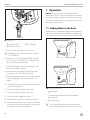
7.1 Adding Water to the Bowl
Adding water to an empty bowl helps prevent holding
tank odors from entering the living space. Adding water
is recommended prior to flushing solids and toilet paper.
q
11 Adding Water to the Bowl
q
Add Water
1. To add water to the bowl, press the flush pedal
part-way down.
2. Release the pedal.
I
To avoid a possible overflow, the water flow will
stop automatically if the pedal is pressed too long.

11
EN
MasterFlush 7600 Series Toilet Maintenance
7.2 Flushing the Toilet
NOTICE: Flush only water, bodily wastes, and rapid-
dissolving toilet tissue. Do not flush foreign objects. Do
not flush wet wipes, sanitary napkins, diapers, paper
cups, cotton swabs, food, hair, or liquids such as oils or
solvents. Failure to follow these instructions could cause
clogging or damage to the toilet or the toilet system.
q
12 Flushing the Bowl
q
Flush Bowl
1. To flush, press the flush pedal down completely.
2. Release the pedal.
This activates a powerful macerator pump that siphons
the water and waste from the toilet bowl, and then
macerates and propels the effluent to the holding tank.
I
Residual water trickle in ceramic bowls: due to
the integrated rim of this toilet bowl, water may
continue to slowly trickle into the toilet bowl for
up to 20 minutes aer flushing. If the water trickle
continues aer 30 minutes, replace the water valve.
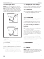
7.3 Changing the Flush Settings
This section describes two flush settings offered to help
manage water usage and how to apply each setting.
7.3.1 Normal Flush
I
The normal flush setting uses 0.8 gal (3 L) per flush
and adds water to the bowl aer every flush.
To change the flush setting from dry bowl to normal
flush, press the flush pedal for ten seconds.
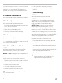
7.3.2 Dry Bowl Flush
I
The dry bowl flush setting uses 0.2 gal. (0.8 L) per
flush and does not add water to the bowl.
To change the flush setting from normal to dry bowl,
press the flush pedal for approximately ten seconds.
7.4 Understanding the Full Tank
Indicator
I
If an optional tank monitor is not installed, skip to
“Maintenance” on page11.
When an optional tank monitor system is installed
and operational, a solid red indicator light on the tank
monitor control panel will indicate the holding tank is
full. Flushing will be disabled to prevent overfilling the
holding tank.
To restore electrical power to the toilet for flushing,
empty or discharge the holding tank contents until the
indicator is off. Additional features and indicators may be
available based on the tank monitor model.
8 Maintenance
This section describes recommended cleaning and
maintenance procedures.
8.1 Cleaning
NOTICE: Do not clean the toilet with abrasive cleaners,
caustic chemicals, or lubricants and cleaners that contain
alcohols or petroleum distillates. Using them could
cause damage to internal seals.

12
EN
Maintenance MasterFlush 7600 Series Toilet
For routine cleaning, use Dometic
®
Toilet Bowl Cleaner.
If this cleaner cannot be found in your area, contact
Dometic for your nearest dealer. If the cleaner is not
available, use almost any non-abrasive bathroom and
toilet bowl cleaner. Follow the label instructions.
8.2 Routine Maintenance
This section describes routine maintenance procedures.
8.2.1 Monthly
This section describes monthly maintenance.
1. Inspect the toilet, plumbing, plumbing connections,
wires, and wire connections.
2. Open and close all plumbing valves.
3. Check any in-line water filters for blockage.
8.2.2 Yearly
This section describes yearly maintenance.
Check the water valve filter.
I
Check the water valve filter if the water flow into the
toilet becomes insufficient.
8.2.3 Extended Periods of Non-Use
NOTICE: The macerator toilet and sanitation system
should be protected if the toilet will not be used for
more than two weeks, especially in hot weather.
NOTICE: Do not use detergent that contains bleach or
environmentally harmful substances.
Complete these steps to protect the toilet before
storage or before two or more weeks of non-use.
1. Flush the toilet in normal mode and add 4oz (118ml)
of liquid biodegradable laundry detergent.
2. Flush the toilet at least five times.
3. Turn off the water supply to the toilet.
4. Flush the toilet three times without water.
I
This procedure will minimize any remaining water in
the macerator pump.
5. Turn off the power to the toilet.
6. If the system will be subjected to freezing
temperatures, continue with “Winterizing” on
page12.
8.3 Winterizing
NOTICE: This toilet is not intended for use when
exposed to temperatures below freezing.
NOTICE: Never leave the vehicle unoccupied for
extended periods of time with the municipal water
supply or the onboard water pump turned on when
there is a possibility of freezing temperatures.
NOTICE: Never use automotive-type antifreeze
(ethylene glycol) in freshwater systems. Use only
nontoxic antifreeze (propylene glycol) designated for
potable water systems. See the vehicle owner’s manual.
At the end of each camping season, or when the vehicle
is stored for long periods of time when the toilet may be
exposed to freezing temperatures, the system should be
winterized by using potable water-safe antifreeze.
Complete these steps to winterize the toilet:
1. Drain the potable water tank and empty the waste
holding tank.
2. Add freshwater antifreeze to the potable water tank
according to the antifreeze manufacturer instructions.
3. Flush the toilet several times until the antifreeze
mixture has flowed completely through the toilet, the
macerator pump, and the holding tank.
4. Turn off the power to the toilet.
I
Each installation is different, so the antifreeze
mixture amounts may vary. User discretion is
required to assure adequate protection.

13
EN
MasterFlush 7600 Series Toilet Troubleshooting
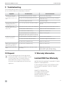
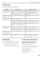
9 Troubleshooting
The following table describes common occurrences that
are not a result of defective workmanship or materials.
Symptom Possible Cause Service Instruction
The flush cycle operates
correctly but the water in the
bowl empties slowly or not
at all.
The discharge piping is pinched or kinked. Check the discharge piping.
The trap or the discharge piping is blocked. Plunge the line or squeeze the trap assembly to
clear the blockage.
The macerator pump is blocked. Clear the blockage.
The macerator pump makes
unusually loud noise or
continually trips the breaker.
There is foreign material in the pump chamber. Clear the foreign material from the pump
chamber.
The flush cycle is not
activated aer pressing the
flush pedal.
Electrical power to the toilet is off or disrupted. Check the wiring and circuit breakers or fuses.
The flush pedal is malfunctioning. Replace the switch in the flush pedal.
The circuit board is malfunctioning. Replace the circuit board.
If an optional tank monitor is installed: the
holding tank is full and the signal from the tank
has shut down the electrical power to the toilet.
Empty the holding tank.
Insufficient or no water
enters the toilet bowl.
The water supply line is pinched or kinked. Check the water supply line.
The screen in the water valve is blocked. Clear the blockage at the water valve.
The water valve is malfunctioning. Replace the water valve.
Water trickles slowly into the
toilet bowl for longer than
30 minutes aer flushing.
The water valve is malfunctioning. Replace the water valve.
The anti-siphon valve leaks
water.
The valve is obstructed, or the valve or valve
seat is faulty.
Manipulate the valve tab.
Pour hot water on the valve to clean it.
If unresolved, replace the trap assembly.
10 Disposal
M
Place the packaging material in the appropriate
recycling waste bins, whenever possible. Consult
a local recycling center or specialist dealer for
details about how to dispose of the product in
accordance with all applicable national and local
regulations.
11 Warranty Information
Limited ONE-Year Warranty
LIMITED ONE-YEAR WARRANTY AVAILABLE AT WWW.
DOMETIC.COM/WARRANTY.
IF YOU HAVE QUESTIONS, OR TO OBTAIN A COPY
OF THE LIMITED WARRANTY FREE OF CHARGE,
CONTACT:
DOMETIC CORPORATION
CUSTOMER SUPPORT CENTER
1120 NORTH MAIN STREET
ELKHART, INDIANA, USA 46514
1-800-544-4881 OPT 1

14
Sommaire Toilette MasterFlush série 7600
1 Explication des symboles et consignes de
sécurité ............................... 14
1.1 Reconnaître les consignes de sécurité .....14
1.2 Comprendre les mots-indicateurs ........14
1.3 Directives supplémentaires ..............15
1.4 Messages de sécurité d’ordre général .....15
2 Informations générales ................. 15
2.1 Identification du modèle ................16
2.2 Emplacements des composants ..........16
3 Indication ............................. 17
4 Caractéristiques techniques ............. 17
4.1 Matériaux des composants ..............17
4.2 Exigences d’installation ................17
4.3 Dimensions de la cuvette de toilette ......18
4.4 Dimensions approximatives .............18
5 Diagramme de câblage ................. 19
6 Installation ............................ 19
6.1 Préparation de l’installation de la toilette ...19
6.2 Retrait d’une toilette existante ............20
6.3 Installation de la toilette ................20
7 Fonctionnement .......................23
7.1 Ajout d’eau dans le bol .................23
7.2 Tirage de la chasse d’eau ...............23
7.3 Modification des paramètres de chasse
d’eau ...............................24
7.4 Comprendre l’indicateur de réservoir plein .24
8 Entretien ..............................24
8.1 Nettoyage ...........................24
8.2 Entretien régulier ......................24
8.3 Hivérisation ..........................25
9 Dépannage ...........................26
10 Élimination ............................26
11 Informations de garantie ................ 26
Sommaire
Liste des centres de service et des revendeurs
Consultez: www.dometic.com
Lire attentivement ces instructions. Ces instructions
DOIVENT rester avec ce produit.
FR
1 Explication des symboles et
consignes de sécurité
Ce manuel contient des consignes de sécurité et des
instructions pour aider l’utilisateur à éliminer ou réduire
le risque d’accidents et de blessures.
1.1 Reconnaître les consignes de
sécurité
C’est le symbole d’alerte à la sécurité. Il signale
des risques de blessures physiques. Obéir à tous les
messages de sécurité qui suivent ce symbole pour
éviter les risques de blessures ou de mort.
1.2 Comprendre les mots-
indicateurs
Un mot-indicateur identifie les messages de sécurité et
les messages liés aux dégâts matériels, et signale aussi le
degré ou niveau de gravité du danger.
DANGER!
Indique une situation dangereuse qui, si elle n’est
pas évitée, causera la mort ou des blessures
graves.
AVERTISSEMENT
Indique une situation dangereuse qui, si elle n’est
pas évitée, peut causer la mort ou des blessures
graves.
ATTENTION
Indique une situation dangereuse qui, si elle n’est
pas évitée, peut causer des blessures légères ou
modérées.
AVIS : Utilisé pour signaler des pratiques non liées à
une blessure physique.
I
Fournit des renseignements additionnels sans
rapport avec des blessures physiques.

15
FR
Toilette MasterFlush série 7600 Informations générales
1.3 Directives supplémentaires
Pour réduire le risque d’accidents et de blessures,
observer les directives suivantes avant de continuer à
installer, utiliser ou entretenir cet appareil:
• Lire et suivre toutes les consignes de sécurité et les
instructions.
• Lire et comprendre ces instructions avant
l’installation, l’utilisation ou l’entretien de ce produit.
• L’installation doit se conformer à tous les codes
locaux ou nationaux applicables, y compris la toute
dernière édition des normes suivantes:
États-Unis
– ANSI/NFPA 70, Code national de l’électricité
(CNE)
– ANSI/NFPA 1192, Code des véhicules récréatifs
– ANSI Z21.57, Code des véhicules récréatifs
Canada
– CSA C22.1, Parties l et ll, Code canadien de
l’électricité
– CSA Z240 RV Series, véhicules récréatifs
1.4 Messages de sécurité d’ordre
général
AVERTISSEMENT: RISQUE DE DÉCHARGE
ÉLECTRIQUE, DE DÉPART DE FEU ET/OU
D’EXPLOSION. Le non-respect de ces
avertissements pourrait entraîner de graves
blessures, voire la mort.
• Couper le courant avant d’effectuer toute installation
électrique ou tout entretien.
• Faire attention en diagnostiquant et/ou ajustant les
composants d’un appareil électrique.
• Utiliser uniquement des pièces et composants de
rechange Dometic spécifiquement approuvés pour
une utilisation avec cet appareil.
• Éviter l’installation, le réglage, les altérations,
les réparations ou la maintenance incorrects de
l’appareil. Les réparations et la maintenance doivent
être confiées à un agent technique qualifié.
• Ne pas modifier ce produit d’une quelconque manière.
Une modification peut être extrêmement dangereuse.
• Ne pas remplir excessivement le réservoir. Afin de
réduire le risque de remplissage excessif, utiliser le
circuit d’arrêt pour réservoir plein, situé dans le module
de contrôle électronique de la toilette. Un système
optionnel de surveillance de réservoir Dometic peut
générer un signal de réservoir plein et désactiver
le rinçage jusqu’à ce que le réservoir soit vidé. Un
remplissage excessif du réservoir peut causer de
graves dommages au système d’assainissement,
comme la rupture du réservoir et le déversement du
contenu de celui-ci dans la maison motorisée.
2 Informations générales
Cette section fournit des informations sur l’outillage et
les pièces pour la toilette MasterFlush
®
série 7600.
I
Les images utilisées dans ce document sont
uniquement fournies à titre de référence. Les
composants et leur emplacement peuvent varier
selon le modèle. Les mesures peuvent varier de
±0,38 po (10 mm).
Ensembles inclus Quantité
Ensemble de matériel de
montage
(Bride de plancher ou installation
à distance)
1
Toilette MasterFlush série
7600
1
Outils recommandés
Pince ou clé ajustable Perceuse
Clé 7/16 po (11 mm) Outils de connexion
électrique
Pièces facultatives
Les toilettes MasterFlush série 7600 peuvent être
raccordées à l’un des nombreux systèmes de
surveillance des réservoirs de Dometic pour offrir
un suivi précis et continu de la capacité du réservoir.
Contactez le centre d’assistance clientèle de Dometic
ou visitez le www.dometic.com pour obtenir plus de
renseignements.

16
FR
Informations générales Toilette MasterFlush série 7600
2.1 Identification du modèle
L’étiquette d’identification du modèle de toilettes se
trouve sur la base de la toilette, sous le robinet d’eau.
Préparez ces informations avant de contacter Dometic
pour obtenir un service.
Loreasm
Loreasam
Model :
Item :
123456789
PNC :
123456789
Serial :
123456789
SO 1234
1 Exemple d’identification de modèle
2.2 Emplacements des composants
Cette section identifie les composants de la toilette.
e
w
o
r
t
u
a
g
f
f
d
s
y
i
q
2 Emplacements des composants
q
Valve anti-siphon/
Tube de décharge
supérieur
o
Dispositif anti-
refoulement/Tuyau
d’alimentation de la
cuve
w
Couvercle du
dispositif anti-
refoulement
a
Valve d’eau
e
Siège de toilette
s
Ensemble de
matériel pour le
montage des brides
de plancher
1
r
Cuvette de la toilette
t
Base de la toilette
y
Joint de bride de
plancher
d
Module de régulation
u
Ensemble de pédale
de chasse d’eau
f
Couvercle de la
pompe/base
i
Tuyau de décharge/
Siphon
g
Pompe dilacératrice/
Ensemble de montage
1
Non illustré: ensemble de matériel pour l’option de montage à distance.

17
FR
Toilette MasterFlush série 7600 Indication
3 Indication
La toilette MasterFlush série 7600 (ci-après nommée
MasterFlush) est une toilette à chasse d’eau électrique
qui broie les déchets et les pompe vers un réservoir ou
vers un autre système de stockage/d’élimination des
effluents. La MasterFlush offre les avantages suivants:
• Une fonction pratique de chasse d’eau électronique
permet d’ajouter de l’eau ou de tirer la chasse en
appuyant sur la pédale de chasse.
• Deux réglages de la consommation d’eau pour
la chasse d’eau offrent une certaine souplesse. La
chasse d’eau normale utilise 0,8gal (3l) et ajoute de
l’eau dans le bol après une chasse d’eau. Le bol sec
utilise 0,2gal (0,8l) et n’ajoute pas d’eau au bol.
• Un lieu d’installation polyvalent offre une certaine
souplesse. La puissante pompe dilacératrice permet
de placer la toilette jusqu’à 40 pi (12,2m) du réservoir
ou d’une autre destination de la ligne de décharge
(méthode d’installation à distance).
• Le dispositif de sécurité d’arrêt automatique du
réservoir plein permet d’éviter les dommages aux
maisons motorisées. Lorsqu’elles sont connectées
à un système d’indication du niveau du réservoir
de stockage, la toilette ne tire pas la chasse d’eau
lorsque le réservoir de stockage est plein et empêche
le remplissage excessif du réservoir.
Le fabricant n’endosse aucune responsabilité en cas de
dommages dans les cas suivants:
• Assemblage ou branchement incorrect
• Endommagement du produit résultant des influences
mécaniques et d’une tension excessive
• Altération du produit sans la permission expresse du
fabricant
• Utilisation à d’autres fins que celles décrites dans le
manuel d’utilisation
Dometic Corporation se réserve le droit de modifier
l’apparence et les caractéristiques techniques de
l’appareil sans préavis.
4 Caractéristiques techniques
La section suivante présente les matériaux, les exigences
d’installation et les dimensions approximatives des toilettes.
4.1 Matériaux des composants
Siège de toilette
Bois émaillé
Cuvette de toilette
Céramique vitreuse
Base de la cuvette de
toilette
Polypropylène
Pédale de chasse d’eau
Polypropylène
Corps de pompe
dilacératrice
Polypropylène armé de verre
Robinet d’eau
Polypropylène
Dispositif anti-
refoulement
ABS/Polypropylène
Joint de bride de
plancher
Caoutchouc nitrile, mousse
4.2 Exigences d’installation
Les tableaux suivants présentent les dimensions
approximatives de la toilette MasterFlush, ainsi que ses
options en matière d’électricité, d’alimentation en eau et
d’évacuation.
4.2.1 Électrique
Consommation
d’énergie
15A/12V c.c.
Coupe-circuit/fusible 20A/12V c.c.
Câblage
Voir les normes ANSI/RVIA
LV et NFPA 70/NEC pour les
calibres de fil recommandés
(États-Unis). Voir les normes
CEC I et II pour les calibres de fil
recommandés (Canada).
4.2.2 Arrivée d’eau
Raccord 0,5po (13mm) NPT
Débit 3 à 5gpm (11,4 à 18,9lpm)
recommandé*
2gpm (9,5lpm) minimum
Pression statique 3 à 100 PSI (207 à 690kPa)
*Une alimentation en eau qui dépasse 5gpm (18,9lpm) peut nécessiter
un limiteur de débit à l’entrée des toilettes.

18
FR
Caractéristiques techniques Toilette MasterFlush série 7600
4.2.3 Options de décharge
Option de bride de
plancher
Bride de plancher
3po (76mm) DI;
épaisseur: 0,25 à 0,4po
(6à11mm)
Option à distance
(n’est pas monté sur
la bride directement
au-dessus du
réservoir)
Taille des tuyaux d’assainissement
DI 1,5 po (38 mm) ou 1 po (25 mm)
Tuyau horizontal
40pi (12,2m) maximum**
**Vérifiez si le débit d’évacuation est suffisant si l’installation s’approche de
cette distance.
Pour des directives additionnelles sur l’installation de la cuvette de toilette
dans un VR, voir les normes ANSI 1192 et Z240 RV Series, véhicules récréat-
ifs, s’il y a lieu. Les caractéristiques techniques sont sujettes à modification
sans préavis.
4.3 Dimensions de la cuvette de
toilette
e
q
u
y
w
t
r
3 Dimensions et dégagements de la toilette
q
15po (381mm)
t
14,8po (375mm) de
l’arrière vers l’avant de la
base
w
33,9po (860mm)
lorsque le siège est
relevé
y
Hauteur du siège de 18,4
po (467mm)
e
20po (508mm)
u
19po (483mm)
r
Approximativement
10 po (254 mm)
4.4 Dimensions approximatives
e
r
w
q
t
y
u
4 Dimensions et dégagements approximatifs
q
Mur du fond
t
Mur de droite
w
Mur de gauche
y
11po (279mm)
e
10po (254mm)
u
11po (279mm)
r
Bride de plancher

19
FR
Toilette MasterFlush série 7600 Diagramme de câblage
5 Diagramme de câblage
Cette section fournit le diagramme de câblage de la
toilette MasterFlush.
Water Valve
Circuit Board
with Internal Fuse
Motor
Full Tank Float
OPTIONAL (recommended)
DTM01 Panel Option
+12 VDC Input
Input Power Supply -12 VDC
+12 VDC Input
- VDC Input
Fuse or Breaker
0.5 AMP
Fuse or Breaker
25 AMP
Toilet
Brown
Brown
Orange
Black
Black
Red
Yellow
1 2 7
3 4 5 6
Black
Red
Blue
5 Diagramme de câblage
6 Installation
AVERTISSEMENT : RISQUE DE DÉCHARGE
ÉLECTRIQUE.
Coupez le courant avant d’effectuer toute
installation électrique ou tout entretien. Le non-
respect de cet avertissement pourrait entraîner de
graves blessures, voire la mort.
AVIS : Ne pas installer la toilette dans une douche.
Veillez à respecter les conditions d’installation
recommandées dans la section «Caractéristiques
techniques» en page17.
AVIS : Assurez-vous que la pédale, lorsqu’elle est
enfoncée, touche la même surface plane que la toilette
installée.
AVIS : Ne pas trop serrer les écrous de fixation.
Pouréviter toute déformation de la base, alternez entre
les côtés lors du serrage.
AVIS : Lorsque vous reconnectez la ligne d’alimentation
en eau, faites attention de ne pas trop serrer.
Cette section décrit les processus de préparation, de
retrait et d’installation de la toilette.
6.1 Préparation de l’installation de
la toilette
1. Vérifiez que l’emplacement répond à toutes les
recommandations pour le nouveau modèle. Voir la
Figure3 et la Figure4.
2. Coupez le courant à l’emplacement de la toilette.

20
FR
Installation Toilette MasterFlush série 7600
3. Coupez l’arrivée d’eau à l’emplacement de la toilette.
6.2 Retrait d’une toilette existante
I
Si vous devez enlever une toilette existante, référez-vous
à la section «Installation de la toilette» en page20.
1. Débranchez l’alimentation de la toilette.
2. Débranchez et vidangez la conduite d’alimentation en eau.
3. Retirez les vis et les boulons de maintien de la toilette.
4. Enlevez la cuvette de toilette du plancher.
5. Retirez et jetez l’ancien joint de bride de plancher, les
boulons de maintien et tout débris d’enlèvement.
6.3 Installation de la toilette
Cette section décrit les deux options d’installation de la toilette.
6.3.1 Installation avec bride de plancher
I
Pour installer la toilette plus loin du réservoir de
stockage, passez à la section «Installation à distance» en
page22.
AVIS : Lors de l’abaissement de la toilette sur la bride
de plancher, la toilette doit être alignée de manière à ce
que la sortie à la base s’insère dans le trou de sortie de la
bride de plancher.
AVIS : La bride de plancher doit être fixée au sol avec un
minimum de quatre vis (huit sont recommandées).
Effectuez ces étapes pour réaliser une installation de
toilette avec une bride de plancher:
1. Vérifiez que la surface supérieure de la bride de plancher est
propre et exempte de tout débris ou produit d’étanchéité.
q
w
e
6 Installation des boulons en T
q
Boulons en T
e
Bride de plancher
w
Fentes
2. Vérifiez que les trous de fixation de toilette de la
nouvelle bride sont au bon endroit. Voir la Figure4 et
la Figure6.
3. Fixez la bride de plancher au sol.
4. Insérez les deux boulons en T dans les fentes de la
bride de plancher.
La page est en cours de chargement...
La page est en cours de chargement...
La page est en cours de chargement...
La page est en cours de chargement...
La page est en cours de chargement...
La page est en cours de chargement...
La page est en cours de chargement...
La page est en cours de chargement...
-
 1
1
-
 2
2
-
 3
3
-
 4
4
-
 5
5
-
 6
6
-
 7
7
-
 8
8
-
 9
9
-
 10
10
-
 11
11
-
 12
12
-
 13
13
-
 14
14
-
 15
15
-
 16
16
-
 17
17
-
 18
18
-
 19
19
-
 20
20
-
 21
21
-
 22
22
-
 23
23
-
 24
24
-
 25
25
-
 26
26
-
 27
27
-
 28
28


dans d''autres langues
Documents connexes
-
Dometic MasterFlush 7640 Mode d'emploi
-
-
Dometic Masterflush MF7200 Le manuel du propriétaire
-
-
-
-
-
-
-
