HySecurity SlideDriver II Mode d'emploi
- Catégorie
- Ouvre-porte
- Taper
- Mode d'emploi

EN - User guide
Slide gate operator
SlideDriver™ II
SlideDriver II 15
SlideDriver II 40
SlideDriver II 50F
SlideDriver II 80V
SlideDriver II 200V

2support.hysecurity.com
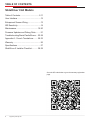
TABLE OF CONTENTS
SlideDriver II All Models
Table of Contents....................................2-11
User Interface ............................................12
Entrapment Sensor Wiring ........................13
IES Sensitivity............................................14
Maintenance ........................................ 15-20
Firmware Updates and Debug Data ..........21
Troubleshooting/Alerts/Faults/Errors ... 22-28
Appendix A - French Translations ........ 29-32
Warranty ....................................................36
............................................37
SlideDriver II Installer Checklist ........... 38-39
Scan the QR code below to go to the warranty registration
page.

3
MX5385 Rev. B ©2023
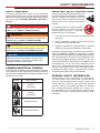
SAFETY MESSAGES
The safety messages below inform you about potential
address level of exposure to operator and are preceded by
one of four words:
DANGER, WARNING, CAUTION or
NOTICE.
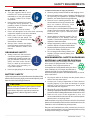
COMMON INDUSTRIAL SYMBOLS
These international safety symbols may appear on product
or in its literature to alert of potential personal injury hazards.
Obey all safety messages that follow these symbols to avoid
possible injury or death.
Symbol Safety Hazard
Attention -
Take Notice
Danger -
Keep Away
Entrapment Zone
Possible Pinch Point
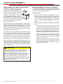
DANGER
Indicates a hazardous situation which, if not avoided,
WILL result in DEATH or SERIOUS INJURY.
WARNING
Indicates a hazardous situation which, if not avoided,
COULD result in DEATH or SERIOUS INJURY.
CAUTION
Indicates a hazardous situation which, if not avoided,
COULD result in MINOR or MODERATE INJURY.
NOTICE
Addresses practices not related to personal injury.
Indicates damage to equipment is probable if the
hazardous situation is not avoided.
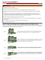
IMPORTANT SAFETY INSTRUCTIONS
Hazards, associated with automatic gates, can
be reduced with proper site design, installation,
and use. Installers, maintenance crews, and
owners/users must read and follow the safety
requirements found in HySecurity® product
manuals.
handle installation of HySecurity Gate
vehicular gate operators. A “qualified”
installer has one of the following:
1.
A minimum of three years experience installing similar
equipment.
2.
Proof of attending a HySecurity Technical Training
seminar within the past three years.
3.
aptitude in gate operator installation and operation.
Underwriter Laboratories (UL) and the American Society for
Testing and Materials (ASTM) are responsible for current
safety standards and regulations regarding gate operators
and automated gates. All aspects of gate installation must
comply with the appropriate safety standard. For the most
up-to-date ASTM F2200 Gate and Fence Standards, refer
to www.astm.org. For UL 325 Safety Standard, refer to
www.ul.com. Consult local government agencies for up-to-
date rules and regulations as certain municipalities have
established licensing, codes or regulations that regulate
automated gate system design and installation.
GENERAL SAFETY INFORMATION
A gate operator is only a component in a gate system.
The other parts of the gate system can include the
gate, the external safety sensors, access controls, and
vehicle detectors. To have a gate system that provides
for safety, security, and reliable operation it is essential
these components operate together as a system. It is
the responsibility of the system designer and/or installer
to ensure any safety or operational issues have been
addressed.
SAFETY REQUIREMENTS

4support.hysecurity.com
WARNING
To reduce the risk of injury or death:
1. READ AND FOLLOW ALL INSTRUCTIONS.
2. Never let children operate or play with gate controls. Keep the remote control away from children.
3. Always keep people and objects away from the gate. NO ONE SHOULD CROSS THE PATH OF THE MOVING
GATE.
4. Test the gate operator monthly. The gate MUST reverse on contact with a rigid object or stop when an object
activates the non-contact sensors. After adjusting the force or the limit of travel, retest the gate operator. Failure to
adjust and retest the gate operator properly can increase the risk of injury or death.
5. Use the emergency release only when the gate is not moving.
6.
gate hardware.
7. The entrance is for vehicles only. Pedestrians must use separate entrance.
8. SAVE THESE INSTRUCTIONS.
IDENTIFYING GATE OPERATOR CATEGORY AND UL 325 USAGE CLASS
Class I Class I: Intended for use in a location of one to four single family dwellings
or a parking area associated with one to four single family dwellings.
Class II
Class II: Intended for use in a commercial location or building such as a multi-
stores or other buildings servicing general public.
Class III
Class III: Intended for use in an industrial location or building such as factories
or loading docks or other locations not accessible by the general public.
Class IV
Class IV: Intended for use in guarded industrial locations or buildings such as
an airport security area or other restricted access location, not servicing general
public, in which access is monitored by security personnel or via closed circuitry.
SAFETY REQUIREMENTS

5
MX5385 Rev. B ©2023
VEHICULAR TRAFFIC ONLY
WARNING
to a separate walk-through gate.
Install this gate operator only when:
The operator is appropriate for the construction of the
gate and the Usage Class of the site.
All openings of a horizontal slide gate are guarded or
screened from the bottom of the gate to a minimum of
1.83 m (6 ft) above the ground to prevent a 57.2 mm (2-1/4
in) diameter sphere from passing through the openings
anywhere in the gate, and in that portion of the adjacent
fence that the gate covers in the open position.
All exposed pinch points are eliminated or guarded.
Guarding is supplied for exposed rollers.
The operator is intended for installation only on gates used for
vehicles. Pedestrians must be supplied with a separate access
opening. The pedestrian access opening shall be designed to
promote pedestrian usage. Locate the gate such that persons
will not come in contact with the vehicular gate during the entire
path of travel of the vehicular gate.
The gate must be installed in a location so that enough
clearance is supplied between the gate and adjacent structures
when opening and closing to reduce the risk of entrapment.
Swinging gates shall not open into public access areas.
The gate must be properly installed and work freely in both
directions prior to the installation of the gate operator. Do
not over-tighten the operator clutch or pressure relief valve
to compensate for an improperly installed, improperly
functioning, or damaged gate.
Permanently mounted controls intended for user activation
must be located at least 1.83 m (6 ft) away from any moving
part of the gate and where the user is prevented from
reaching over, under, around or through the gate to operate
the controls.
Exception: Emergency access controls only accessible
placed at any location in the line-of-sight of the gate.
The Stop and/or Reset button must be located in the line-
of-sight of the gate. Activation of the reset control shall not
cause the operator to start.
A minimum of two (2) WARNING SIGNS shall be installed,
in the area of the gate. Each placard is to be visible by
persons located on the side of the gate on which the placard
is installed.
For gate operators utilizing a non-contact sensor (Photo
Eye):
See instructions on the placement of non-contact
sensors for each type of application.
Care shall be exercised to reduce the risk of nuisance
tripping, such as when a vehicle trips the sensor while
the gate is still moving.
One or more non-contact sensors shall be located where
the risk of entrapment or obstruction exists, such as the
perimeter reachable by a moving gate or barrier.
For a gate operator utilizing a contact sensor (Edge):
One or more contact sensors shall be located where
the risk of entrapment or obstruction exists, such as at
the leading edge, trailing edge, and postmounted both
inside and outside of a vehicular horizontal slide gate.
A hardwired contact sensor shall be located and its
wiring arranged so that the communication between
the sensor and the gate operator is not subjected to
mechanical damage.
A wireless device that transmits radio frequency (RF)
signals to the gate operator for entrapment protection
functions shall be located where the transmission of
the signals are not obstructed or impeded by building
structures, natural landscaping or similar obstruction. A
wireless device shall function under the intended end-
use conditions.
One or more contact sensors shall be located on
the inside and outside leading edge of a swing gate.
Additionally, if the bottom edge of a swing gate is greater
than 152 mm (6 in) but less than 406 mm (16 in) above
the ground at any point in its arc of travel, one or more
contact sensors shall be located on the bottom edge.
USE OF VEHICLE DETECTORS
Use of vehicle detectors (loop detectors) is strongly
encouraged to prevent damage to vehicles caused by
gates closing on them. This is not considered to be a safety
item as most vehicle detectors cannot provide protection
to pedestrians. In some situations, photoelectric devices
may be used as vehicle detectors, but should be wired
accordingly.
GATE CONSTRUCTION AND SAFETY
Gate construction plays a very important role in ensuring
the safety of any automated gate system. The standard for
gate construction is ASTM F2200. Below are key areas to
address in gate design for safety. For complete information
consult the standard. Copies of the standard are available
at: https://www.astm.org/Standards/F2200.htm.
SAFETY REQUIREMENTS

6support.hysecurity.com
Another source of information is available from DASMA, the
Door and Access System Manufacturer’s Association. The
Association publishes Technical Data Sheets, one of which
concerns ASTM F2200. For more information, see:
http://www.dasma.com/PDF/Publications
General Requirements for gate construction:
Gates shall be constructed in accordance with the
provisions given for the appropriate gate type listed.
Refer to ASTM F2200 for additional gate types.
Gates shall be designed, constructed and installed to not fall
over more than 45 degrees from the vertical plane, when a
gate is detached from the supporting hardware.
Gates shall have smooth bottom edges, with vertical bottom
edged protrusions not exceeding 0.50 in (12.7 mm) other
than the Exceptions listed ASTM F2200.
The minimum height for barbed wire shall not be less than 6
ft (1.83 m) above grade. The minimum height for barbed tape
shall not be less than 8 ft (2.44 m) above grade.
An existing gate latch shall be disabled when a manually
A gate latch shall not be installed on an automatically
operated gate.
Protrusions shall not be permitted on any gate. Consult
ASTM F2200 for exceptions.
Gates shall be designed, constructed and installed such
that their movement shall not be initiated by gravity when
an automatic operator is disconnected.
For pedestrian access in the vicinity of an automated
vehicular gate, a separate pedestrian gate shall be
provided. The pedestrian gate shall be installed in a
location such that a pedestrian shall not come in contact
with a moving vehicular access gate. A pedestrian gate
shall not be incorporated into an automated vehicular
gate panel.
Any non-automated gate that is to be automated shall be
used for pedestrian access and to vehicular gates not
to be automated.
Any existing automated gate, when the operator requires
replacement, shall be upgraded to conform to the
The following provisions shall apply to Class I, Class II,
Class III, and Class IV vehicular horizontal slide gates:
All weight bearing exposed rollers 8 ft (2.44 m), or less, above
grade shall be guarded or covered.
All openings shall be designed, guarded, or screened from
the bottom of the gate to the top of the gate or a minimum of
72 inch (1.83 m) above grade, whichever is less, to prevent
a 2-1/4 inch (57 mm) diameter sphere from passing through
the openings anywhere in the gate, and in that portion of
the adjacent fence that the gate covers in the open position.
The gate panel shall include the entire section of the moving
gate, including any back frame or counterbalance portion of
the gate.
A gap, measured in the horizontal plane parallel to the
roadway, between a fixed stationary object nearest the
roadway (such as a gate support post) and the gate frame
when the gate is in either the fully open position or the fully
closed position, shall not exceed 2-1/4 inches (57 mm).
inches (406 mm) from the gate frame shall not be required
to comply with this section.
Positive stops are provided to limit travel to the designed
fully open and fully closed positions. These stops shall be
installed at either the top of the gate, or at the bottom of the
gate where such stops shall horizontally or vertically project
no more than is required to perform their intended function.
assure that the gate will enter a receiver guide. Consult ASTM
F2200 for details on various gate panel types.
EXTERNAL ENTRAPMENT PROTECTION
SENSORS
Most HySecurity gate operators are equipped with a Type A,
Inherent Entrapment Sensor (IES). UL 325 Safety Standard
compliance requires installation of external entrapment
protection sensors, the number of which, depends on
entrapment hazards that exist at each particular installation.
To comply with UL 325, the following external sensors may
be used:
Contact sensors, such as edge sensors
Non-contact sensors, such as photo eyes
Site designer or installer can choose either photo eyes, edge
sensors, or a combination of these devices.
UL 325 Safety Standard for automatic sliding gates
combination of both devices be installed to protect against
pedestrian entrapment in BOTH directions of gate travel and
wherever entrapment hazards exist.
SAFETY REQUIREMENTS

7
MX5385 Rev. B ©2023
SAFETY REQUIREMENTS
UL 325 LISTING: Edge sensors and photo eyes must
be tested and labeled as “Recognized Components” or
be deemed acceptable for use in a gate operator. Study
installation to determine where greatest entrapment
risks exist. Locate edge sensors and/or photo sensors
are used so that pedestrians are protected from entrapment
in both directions of gate travel and all hazard areas are fully
protected. Most HySecurity gate operators require external
entrapment sensors that utilize Normally Closed (NC) contact
means of monitoring. HySecurity gate operators utilizing the
SmartCNX Controller or the SmartTouch 720/725 Controller
require external entrapment sensors that have a 10k Ohm
or 4-wire pulsed monitoring scheme. Refer to UL website at
www.ul.com
for most up-to-date list of gate operator safety
standards (UL 325). Refer to
www.astm.org for a complete
list of ASTM F2200 Gate and Fence Standards.
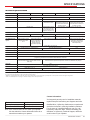
hysecurity.com | 800-321-9947 Page 1 of 2
Nice | HySecurity Recommended Sensors Control Boards
Mfg. Part # or
Model Brand
Nice |
Hysecurity
Part #
Max
Range
Smart
Touch
Smart
DC SmartCNX 1050 Mercury
310
Photo Eyes
(Retro
-reective)
E3K-R10K4-NR-1 Omron MX000999 40 ft • • •
NIR-50-325 EMX -45 ft • • • • •
IRB-RET EMX -53 ft • • • • •
E-931-S50RRGQ Seco-Larm -46 ft • • • •
Photo Eyes
(Thru-Beam)
Blue Bus
Era Photo Eyes
Nice |
HySecurity
EPMB/A
EPMOB/A
EPLOB/A
EPMAB/A
EMBORB/A 45 ft • • •
OVS-50TNR Optex -33 ft • •
IRB-MON EMX MX3990 65 ft • • • •
E-960-D90GQ Seco-Larm -90 ft • • • •
Edge
Sensors
Sentir Series ASO Safety
"AS1502-*
AS1501-*" • • • • •
CPT210-2U-#-T2 Miller Edge - • • • • •
Edge Sensor
Converters
Hy2NC (Converts 10K
to NC Monitoring) HySecurity MX4018 • •
GEM103 (Converts 10K
to Pulsed Monitoring) Miller Edge - •
Edge
Wireless
Kits
iGAZE RE Kit
Transmitter
Solutions - • • • • •
WEL-200 EMX - • • • • •
Multi-Input
Module The Solution – MIM-62 Miller Edge - • • • •
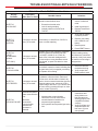
UL 325 Standard:
• The operator shall monitor for the presence of every device at least once during each open and close cycle (32.1.8)
• It shall not be possible to make simple modications in the eld by adding, suppressing or changing, either on the operator or
external entrapment protection device(s), to bypass, interfere with, or otherwise defeat the monitoring function. (32.1.10)
• Entrapment zones are now dened for each gate type (4.23, 4.24, 4.29, 4.34)
Slide Gates: To enable fully automatic operation, all SLIDE gate operators will require a minimum of TWO monitored external
entrapment protection sensors (one for each direction) to protect entrapment zones in both the open and close direction of travel.
Preferred solution for slide gates: A photo eye for the close direction and a hard-wired edge sensor for the open direction that is mounted
to the face of the leading post of the fence behind the gate. (Reach through injuries are the most common hazard associated with
automatic sliding gates)
Swing Gates: To enable fully automatic operation, all SWING gate operators will require a minimum of ONE monitored external
entrapment protection sensor to protect entrapment zones in either the open or close direction of travel. However, an additional
monitored sensor is required if there is a risk of entrapment in both directions of gate travel.
Preferred solution for swing gates: A photo eye for the close direction and/or a hard-wired wraparound edge sensor on the leading edge
of the gate, which protects for both directions of gate travel.
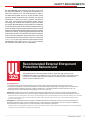
The following sensors have been tested with Nice | HySecurity gate operators by an
independent laboratory and certied to comply with UL 325 7th Edition. Select sensors from
this list for UL compliant gate automation solutions. Contact the sensor manufacturer for
specic recommendations for use.
Recommended External Entrapment
Protection Sensors List
325
hysecurity.com | 800-321-9947 Page 1 of 2
Nice | HySecurity Recommended Sensors Control Boards
Mfg. Part # or
Model Brand
Nice |
Hysecurity
Part #
Max
Range
Smart
Touch
Smart
DC SmartCNX 1050 Mercury
310
Photo Eyes
(Retro
-reective)
E3K-R10K4-NR-1 Omron MX000999 40 ft • • •
NIR-50-325 EMX -45 ft • • • • •
IRB-RET EMX -53 ft • • • • •
E-931-S50RRGQ Seco-Larm -46 ft • • • •
Photo Eyes
(Thru-Beam)
Blue Bus
Era Photo Eyes
Nice |
HySecurity
EPMB/A
EPMOB/A
EPLOB/A
EPMAB/A
EMBORB/A 45 ft • • •
OVS-50TNR Optex -33 ft • •
IRB-MON EMX MX3990 65 ft • • • •
E-960-D90GQ Seco-Larm -90 ft • • • •
Edge
Sensors
Sentir Series ASO Safety
"AS1502-*
AS1501-*" • • • • •
CPT210-2U-#-T2 Miller Edge - • • • • •
Edge Sensor
Converters
Hy2NC (Converts 10K
to NC Monitoring) HySecurity MX4018 • •
GEM103 (Converts 10K
to Pulsed Monitoring) Miller Edge - •
Edge
Wireless
Kits
iGAZE RE Kit
Transmitter
Solutions - • • • • •
WEL-200 EMX - • • • • •
Multi-Input
Module The Solution – MIM-62 Miller Edge - • • • •
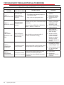
UL 325 Standard:
• The operator shall monitor for the presence of every device at least once during each open and close cycle (32.1.8)
• It shall not be possible to make simple modications in the eld by adding, suppressing or changing, either on the operator or
external entrapment protection device(s), to bypass, interfere with, or otherwise defeat the monitoring function. (32.1.10)
• Entrapment zones are now dened for each gate type (4.23, 4.24, 4.29, 4.34)
Slide Gates: To enable fully automatic operation, all SLIDE gate operators will require a minimum of TWO monitored external
entrapment protection sensors (one for each direction) to protect entrapment zones in both the open and close direction of travel.
Preferred solution for slide gates: A photo eye for the close direction and a hard-wired edge sensor for the open direction that is mounted
to the face of the leading post of the fence behind the gate. (Reach through injuries are the most common hazard associated with
automatic sliding gates)
Swing Gates: To enable fully automatic operation, all SWING gate operators will require a minimum of ONE monitored external
entrapment protection sensor to protect entrapment zones in either the open or close direction of travel. However, an additional
monitored sensor is required if there is a risk of entrapment in both directions of gate travel.
Preferred solution for swing gates: A photo eye for the close direction and/or a hard-wired wraparound edge sensor on the leading edge
of the gate, which protects for both directions of gate travel.
The following sensors have been tested with Nice | HySecurity gate operators by an
independent laboratory and certied to comply with UL 325 7th Edition. Select sensors from
this list for UL compliant gate automation solutions. Contact the sensor manufacturer for
specic recommendations for use.
Recommended External Entrapment
Protection Sensors List
325

8support.hysecurity.com
28
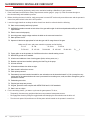
Nice | HySecurity Recommended Sensors Control Boards
Mfg. Part # or Model Brand Nice | Hysecurity
Part #
Max
Range
Smart
Touch
Smart
DC
SmartCNX /
SmartTouch 725 1050 Mercury
310
Photo Eyes
(Retro
-refl ective)
E3K-R10K4-NR-1 Omron MX000999 40 ft • • •
NIR-50-325 EMX -45 ft • • • • •
IRB-RET EMX -53 ft • • • • •
E-931-S50RRGQ Seco-Larm -46 ft • • • •
Photo Eyes
(Thru-Beam)
Blue Bus
Era Photo Eyes
Nice |
HySecurity
EPMB/A
EPMOB/A
EPLOB/A
EPMAB/A
EMBORB/A 45 ft • • •
OVS-50TNR Optex -33 ft • •
IRB-MON* EMX MX3990 65 ft • • • •
E-960-D90GQ Seco-Larm -90 ft • • • •
Edge Sensors Sentir Series** ASO Safety
"AS1502-*
AS1501-*" • • • • •
CPT210-2U-#-T2 Miller Edge - • • • • •
Edge Sensor
Converters
Hy2NC (Converts 10K to
NC Monitoring) HySecurity MX4018 • •
GEM103 (Converts 10K to
Pulsed Monitoring) Miller Edge - •
Edge
Wireless Kits iGAZE RE Kit
Transmitter
Solutions - • • • • •
WEL-200 EMX - • • • • •
Multi-Input
Module The Solution – MIM-62 Miller Edge - • • • •
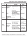
*IRB-MON photo eyes are pre-bundled with HySecurity SwingSmart DC, SlideSmart DC and SlideDriver operators.
**Sentir Series ASO edge sensors are pre-bundled with HySecurity SlideSmart DC, SlideSmart CNX and SlideDriver operators.
UL 325 Standard:
• The operator shall monitor for the presence of every device at least once during each open and close cycle (32.1.8)
• It shall not be possible to make simple modications in the eld by adding, suppressing or changing, either on the operator or
external entrapment protection device(s), to bypass, interfere with, or otherwise defeat the monitoring function. (32.1.10)
• Entrapment zones are now dened for each gate type (4.23, 4.24, 4.29, 4.34)
Slide Gates: To enable fully automatic operation, all SLIDE gate operators will require a minimum of TWO monitored external
entrapment protection sensors (one for each direction) to protect entrapment zones in both the open and close direction of travel.
Preferred solution for slide gates: A photo eye for the close direction and a hard-wired edge sensor for the open direction that is mounted
to the face of the leading post of the fence behind the gate. (Reach through injuries are the most common hazard associated with
automatic sliding gates)
The following sensors have been tested with Nice | HySecurity gate operators by an
independent laboratory and certied to comply with UL 325 7th Edition. Select sensors from
this list for UL compliant gate automation solutions. Contact the sensor manufacturer for
specic recommendations for use.
Recommended External Entrapment
Protection Sensors List
325
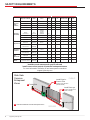
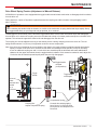
Installers must assess each speci c site and
install sensors that protect all potential entrapment zones.
For more information visit Safety or see latest operator manuals at
support.hysecurity.com
Protects open direction
(EDGE OPEN)
1
A
Install Edge for
Draw-in Zone
Trailing End
Leading End
PUBLIC
SECURE
2
Install Photo eye
Protects Leading End
(EYE CLOSE)
Slide Gate
Common
Entrapment
Zones
Indicates Additional Potential Entrapment Zone
A
SAFETY REQUIREMENTS

9
MX5385 Rev. B ©2023
ELECTRICAL SAFETY
Turn gate operator and all circuit
breakers OFF before performing
maintenance on the gate operator
or making contact with output
receptacles.
Never insert any objects into output
receptacles during operation. The
possibility exists of electrical shock,
electrocution, or death.
Never let power wires lay in water.
Never use damaged or worn wire when connecting
equipment. Inspect for cuts in the insulation.
Never grab or touch a live power
cord or cable with wet hands. The
possibility exists of electrical shock,
electrocution or death.
Always make certain that proper
power has been selected for the job.
See Cable Selection Chart in this
manual.
GROUNDING SAFETY
Always make sure that electrical
circuits are properly grounded to a
suitable earth ground (ground rod)
per the National Electrical Code
(NEC) and local codes. Severe
injury or death by electrocution
can result from operating an
ungrounded operator.
Never use gas piping as an electrical ground.
BATTERY SAFETY
HySecurity operators use sealed Absorbed Glass Mat (AGM)
batteries and HySecurity highly recommends replacing used
batteries with new AGM-type batteries.
CAUTION
Batteries used with HySecurity gate operator contain
materials considered hazardous to environment.
Proper battery disposal is required by federal law.
Refer to Hazardous Waste Regulations federal
guidelines.
To reduce risk of re or injury to persons:
Observe polarity between batteries and charging circuit.
Never mix battery sizes, types, or brands. Charging circuit
on HySecurity DC operators is designed for AGM-type
Exercise care in handling batteries. Be
aware metal found in rings, bracelets, and
keys can conduct electricity, short
batteries, and cause potential injury.
Do not open or mutilate batteries. Battery cells
contain corrosive materials which may cause
burns and other injuries. Material within
batteries is toxic.
Always dispose of batteries properly. Do not
place batteries in fire. Battery cells may
explode. Follow federal guidelines for proper
disposal of hazardous waste.
Always keep battery cables in good working
condition. Repair or replace all worn cables.
Replace batteries according to instructions
found in DC Battery Replacement.
Do not charge frozen battery. Battery can
explode. If frozen, warm the battery to at
least 61°F (16°C).
ENVIRONMENTAL SAFETY/HAZARDOUS
MATERIALS AND PROPER DISPOSAL
Decommissioning is a controlled process used to safely
retire a piece of equipment that is no longer
serviceable. If the equipment poses an
unacceptable and unrepairable safety risk due to
maintain (beyond life-cycle reliability) and is to be
decommissioned (demolition and dismantlement), be sure to
follow rules below.
Do not pour waste or oil directly onto the ground, down a
drain or into any water source.
Contact your country's Department of Public Works or
recycling agency in your area and arrange for proper
disposal of any electrical components, waste or oil
associated with this equipment.
When the life cycle of this equipment is over, remove battery
and bring to appropriate facility for lead reclamation. Use safety
precautions when handling batteries that contain sulfuric acid.
When the life cycle of this equipment is over, it is
recommended that the frame and all other metal and plastic
parts be sent to a recycling center.
Metal and plastic recycling involves the collection of metal and
plastic from discarded products and its transformation into raw
materials to use in manufacturing a new product.
Recyclers and manufacturers alike promote the process of
recycling metal and plastic. Using a metal and plastic recycling
center promotes energy cost savings.
SAFETY REQUIREMENTS

10 support.hysecurity.com
WIND LOAD FACTORS & SITE PREP
Wind load is always a factor when
considering the appropriate gate for a
particular site. Solid gate panels produce
a larger wind load than gates with slats
or open decorative features. If you are
installing a gate operator in a high wind
the gate operator because wind load acts
the same as an obstruction. Good gate
panel design presents a low surface area
to reduce the wind load.
If gate is heavy and near weight capacity of what the gate
semi-solid gate design under certain wind load conditions
may cause damage to gate operator and is not covered by
the HySecurity Limited Warranty.
Several factors play into calculations of wind load on a gate
the United States, search for US government wind speed
maps on the internet. If you don’t know how to calculate for
wind load, ask a mechanical engineer or site architect for
assistance prior to installing gate operator and gate panels.
When the IES trips, it sends a signal to gate operator to stop
and reverse direction. This feature may be falsely triggered
in excessively windy conditions because wind itself, acting
over surface area of gate panel, can provide necessary
force to trigger IES.
CAUTION
Do not adjust IES sensitivity to accommodate for
inappropriately designed gate panels. Loss of IES
sensitivity increases mechanical wear on gate
hardware and gate operator. It may also pose a safety
hazard. Compensating for wind loads by adjusting
IES may set IES sensitivity to a level which, when
encountering an obstruction, ignores obstruction and
fails to reverse direction. For more information, refer to
Adjusting the IES Sensitivity.
MAINTENANCE OF GATE SYSTEMS
To keep your automated gate system performing both safely
and reliably it is important to ensure that the components of
that system are functioning properly.
At least monthly:
Disconnect the gate operator and manually move the
gate through its range of travel. Note any squeaks from
rollers or hinges or areas of binding. The gate should
travel smoothly and quietly throughout its range. If it
does not, contact a gate professional to correct the
problem.
Reconnect the gate operator and perform the following
tests:
•
With the gate opening, block any photo eyes and/
or depress any safety edges used to protect the
open direction. The gate should stop and/or reverse.
•
With the gate closing, block any photo eyes and/or
depress any safety edges used to protect the close
direction. The gate should stop and/or reverse.
•
Using a suitable obstruction in the path of the gate
(a solid, immovable object), run the gate in the open
direction until it contacts the obstruction. The gate
should stop and reverse.
•
Using a suitable obstruction in the path of the gate
(a solid, immovable object), run the gate in the close
direction until it contacts the obstruction. The gate
should stop and reverse.
SAFETY REQUIREMENTS

11
MX5385 Rev. B ©2023
SAFETY REQUIREMENTS
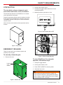
STOP BUTTON
The stop button clears entrapment mode
and resets some faults, errors, and alarms.
The external stop button for the SlideDriver II is located
on the right side of the chassis.
Press the stop button while the gate is opening or closing
to stop gate travel and disable the automatic close timer.
The operator requires a new open or close command to
resume function.
Inform all users of the location of the stop button and its
function.
Figure 1. Stop Button
Figure 2. Remove the cover
Figure 3. Power Switch Set to OFF
EMERGENCY RELEASE
manually move the gate.
To manually release the gate:
1. Remove the cover.
To return SlideDriver II to automatic
operation, follow these steps:
1. Clamp the toggle handle.
2. Set the power switch to ON.
3. Press STOP or RESET to clear any faults.
4. Attach the front cover.
Stop
Button
WARNING
When releasing the handle inside the chassis, be
careful as the mechanism is spring-loaded and drops
do not get pinched, hit, or crushed.
Loosen
cover
screws
Lift
cover
2. Set the power switch to OFF.
3. Unclamp the toggle handle and secure it in the
unclamped position.
4. Manually push the gate open or close.
Figure 4. Slide the Gate Manually
Clamped
Unclamped
Handle
Position

12 support.hysecurity.com
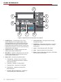
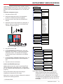
USER INTERFACE
Figure 5. SmartTouch 720/725 Controller User Interface
1. OLED Display – 16 characters per line, 2 line
display. Displays current operator status, menus,
buttons have been pressed for a while. Pressing any
button will turn it back on. This is to save power and
extend the life of the display.
2. Up/Down Arrows – Navigate through menu and
display options while in Menu Mode.
3. Menu/Back
operator status display. Go back from the current
menu (exit the current menu).
4. Status LED – Indicates gate operator status
a. Flashing Red – An Alert, Fault, or Error has
occurred. Immediately shut down the machine
and correct the fault.
b. Solid Red – Operator is in Menu Mode
c. Flashing Green – Operator is in Run Mode
d. Flashing Blue – Operator is pairing with a
Bluetooth device.
e. Alternating Blue and Red/Green – Operator is
communicating with a Bluetooth device.
5. Limit Open/Close
activates limit sensor.
6. Stop/Select – Stops gate travel when in run mode.
setting value
7. Close – Closes the gate while in Run Mode.
8. Open – Opens the gate while in Run Mode.
9. Reset – Press to clear faults and return to Run Mode.
Not functional in Menu Mode.
2
68 7
3
4
1
9
5

13
MX5385 Rev. B ©2023
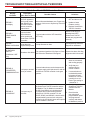
PROGRAMMABLE
INPUTS
EMERGENCY INPUT 0 EMERG CLOSE
1 FIRE DEPT OPEN
SENSOR #1 TYPE 1 NOT USED
2 EYE CLOSE
3 EDGE CLOSE
4 EYE OPEN
5 EDGE OPEN
6 EDGE BOTH
SENSOR #2 TYPE “SEE SENSOR #1 TYPE”
INPUT #1 TYPE 1 NOT USED
2 EYE CLOSE
3 EDGE CLOSE
4 EYE OPEN
5 EDGE OPEN
6 EDGE BOTH
7 NOT USED
8 PARTIAL OPEN
9 OPEN INTERLOCK
10 TIME CLK OPEN
11 NOT USED
12 BLK FREE EXIT
13 EXIT LOOP
14 INSIDE LOOP
15 OUTSIDE LOOP
16 CENTER LOOP
17 LOCK/INTERLOCK
18 AC LOSS INPUT
19 WAKE DISPLAY
25 OPEN INPUT
26 CLOSE INPUT
27 REMOTE INPUT
INPUT #2 TYPE “SEE INPUT #1 TYPE”
INPUT #3 TYPE “SEE INPUT #1 TYPE”
OPEN INPUT 0 DISABLED
1 ENABLED
CLOSE INPUT 0 DISABLED
1 ENABLED
REMOTE INPUT 0 DISABLED
1 ENABLED
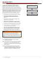
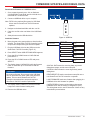
ENTRAPMENT SENSOR WIRING
Install the entrapment sensor:
1. Set power switch to OFF.
2. Install the entrapment sensor in an appropriate
location for entrapment protection (page 8).
3. Route the wires to the inside of the SlideDriver II
chassis.
4. Install the wires into input Sensor #1, Sensor #2, or
Input #1, Input #2, or Input #3 on the SmartTouch
720/725 Controller (Figure 6).
5. Set power switch to ON.
6. In PROGRAMMABLE INPUTS menu, select the
SENSOR TYPE or INPUT TYPE for each external
entrapment sensor. The indicator LED changes
to green when sensor is activated or not installed
correctly.
7. In ENTRAPMENT SENSOR RESPONSE menu, set
the desired response action for each entrapment
type.
8. Test the function of each sensor.
Install a non-BlueBUS photo eye:
Additional photo eyes can connect to the SmartTouch
720/725 Controller terminals Sensor #1 - #2 and Input
#1 - #3. Follow the same instructions for an edge sensor
(Figure 6).
Set any DIP-switches and jumpers according to
manufacturer instructions for 10k output.
Make sure to connect to a Sensor COM port for switched
common for monitoring purposes.
Figure 6. Bundled Sensor Connections
HySecurity provides one edge sensor typically used as
hardwired EDGE OPEN and one photo eye typically used
as EYE CLOSE with the SlideDriver II 15, 40, 50F, and
80V. †
†
(5†)
(15†)
(19†)
†
ENTRAPMENT
SENSOR RESPONSE
PHOTO EYE ALIGN 0 (OFF)
1 (ON)
EDGE CLOSE LOGIC 0 FULL OPEN
1 REVERSE 2S
EYE CLOSE LOGIC 0 STOP ONLY
1 REVERSE 2S
2 FULL OPEN
EYE OPEN LOGIC 0 STOP ONLY
1 REVERSE 2S
IES STOP ONLY 0 (OFF)
1 (ON)
REVERSAL LOGIC 0 FULL OPEN
1 REVERSE 2S
IES SENSITIVITY 0 (MAXIMUM) - 9
(2†)
†
†
†
†
†
†
Note: When Photo Eye Align mode is turned on, the
display will show all the sensor inputs that are
programmed for photo eyes and will show if they
are active or not (a 1 indicates the eye is present
and aligned and a 0 indicates the eye is not aligned
or blocked). Any BlueBUS eye will also show up on
the display.
† = Indicates default
†
†
†

14 support.hysecurity.com
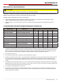
To comply with UL 325 Safety Standards, SlideDriver
II operators are equipped with a Type A, Inherent
hydraulic pressure when a gate is in motion and reverses
direction of gate travel when the pressure exceeds a self-
adapting threshold. A spike in hydraulic pressure can be
caused by the gate hitting a pedestrian, a collision with a
vehicle, failing gate hardware, extreme wind gust, or any
other force applied against the moving gate. To set the
IES sensitivity for your site follow these instructions:
1. Press MENU on the SmartTouch 720/725 Controller.
2. Press the UP or DOWN arrow to navigate to
ENTRAPMENT SENSOR RESPONSE, press
SELECT.
3. Press the UP or DOWN arrow to navigate to IES
SENSITIVITY, press SELECT.
4. Press the UP or DOWN arrow to choose an IES
SENSITIVITY, press SELECT to update the setting.
5. Press BACK until the display shows the operator status.
6. Run the operator for 3 uninterrupted gate cycles so
the IES can adapt to the new setting.
7. Apply force to the leading edge of the moving gate
with an immovable obstruction to trigger the IES.
Gate will stop motion and reverse for at least two
seconds. “SAFE MODE” appears on the display.
8. Cycle the gate a few times to test the IES sensitivity.
Note: The default IES SENSITIVITY of 2 should be
Note: In Safe Mode, the automatic close timer is disabled,
but any open or close input restarts gate motion.
Safe Mode clears when full travel reached or Reset
button pushed.
Note: A second IES trip before Safe Mode is cleared,
results in an Entrapment Mode Alert which can be
cleared with a Reset on the display, an open input,
stop input, or stop button on SlideDriver II cover.
IES SENSITIVITY
WARNING
Do not enter the path of gate travel to test IES
sensitivity. Vehicular gate operators must by their
nature be powerful to function reliably. This power can
cause injury or death to people caught in the moving
gate.
IES SENSITIVITY
0 (MOST SENSITIVE) - 9
ENTRAPMENT
SENSOR RESPONSE

15
MX5385 Rev. B ©2023
MAINTENANCE
MECHANICAL MAINTENANCE
CAUTION
SlideDriver II mechanical maintenance should be performed on a routine basis. The standard operator chassis has zinc
based corrosion protection, but some environments may speed corrosion.
Schedule regular maintenance and look for the following:
Verify center clamp has proper compression (see page 17). Check for drive wheel wear and damage. Fraying
edges or galling indicate that the wheels are due for replacement.
Check for signs of rust. If any areas of rust are found, reduce spread of corrosion by treating areas with a rust
inhibitor.
SLIDEDRIVER OPERATOR MAINTENANCE SCHEDULE
Name of part What to do Check at these recommended monthly intervals
1 3 6 12 24
Gate and hardware Check for damage and wear *1 X
Drive rail Check for proper alignment *2 X
Wheel clamp spring Check for clamping tension *3 X
Drive wheels Check for tightness and wear *4 X
Dual limit sensor Check for proper alignment *5 X
Limit ags Check for proper alignment *5 X
Anchor bolts Check for tightness X
Fluid level Check for loss of uid *6 X
Hydraulic uid Drain and replace uid *6 X
Motor Brushes (DC Only) Replace *7 X
1. Your gate and gate hardware will require more maintenance than your HySecurity operator. A damaged gate or worn hardware may
cause slow or erratic operation and will result in excess drive wheel wear. Lubricate gate hardware more frequently and check for
smooth operation by opening the toggle clamping mechanism and then pushing the gate manually. One person should easily be
able to push all but the largest of gates. Damaged or warped gate panels should be straightened or replaced.
2. See “Drive Rail” on page 16.
3. See “Drive Wheel Spring Tension (Adjustment of Manual Release)” on page 17.
4. Normally, drive wheel life is many years. They are designed to avoid slipping on the rail. Drive wheel life may be greatly shortened
by any of these faults: clamping spring not adjusted correctly, operator or drive rail misaligned in relation to gate panel, badly
18 ft-lb).
5.
to the drive rail. Verify the limit sensors are snug in their mounts.
6. See “Hydraulic System Maintenance” on page 19.
7. DC Operators use DC motors with 4 carbon brushes which wear in normal operation. Worn brushes can damage the DC motor.
Under severe conditions HySecurity recommends that brushes be checked after 2 years or 250,000 cycles and the replacement
interval be adjusted as necessary.

16 support.hysecurity.com
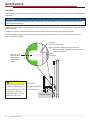
Drive Rail
Verify that the drive rail does not move down, more than 1 in up, or ¼ in side-to-side throughout the entire horizontal travel
of the gate.
MAINTENANCE
NOTICE
The drive rail must not move down or it will rub against the dual limit sensor(s). Adjust the drive rail so it does not rub
on the dual limit sensor(s).
To adjust the rail for side-to-side movements, loosen the U-bolts and insert or remove shims between the rail and the gate
where necessary.
To adjust up or down, loosen the U-bolts and tap the rail with a hammer until the correct height is reached.
base of SlideDriver chassis.
CONCRETE PAD
Gate face*
Use shims as needed.
*Note: The best materials to use for shims are
corrosion resistant materials, such as aluminum
or heavy-duty plastic.
Gate
Structure
Rail Height
AD: Advanced Drive
XD: XtremeDrive
XtremeDrive™
CAUTION
Height from top of drive rail
to bottom of gate operator.
in (230 mm to 250 mm)
XtremeDrive 9½ in to 10 in
(240 mm to 255 mm)
AD
XD
Align top of rail
with label and
notch on the
SlideDriver II
chassis.

17
MX5385 Rev. B ©2023
Drive Wheel Spring Tension (Adjustment of Manual Release)
All SlideDriver II operators come equipped with a toggle handle manual release mechanism to disengage the drive wheels
from the drive rail.
During shipment, a piece of Styrofoam is placed between the coupling nut and the chassis. If the packaging is still in
place, discard it.
MAINTENANCE
WARNING
When releasing the handle inside the chassis, be careful as the mechanism is spring-loaded and drops rapidly. Grasp
To disengage the drive wheels, pull the aluminum toggle handle down. As the lower drive wheel drops and disengages
from the drive rail, it causes the coupling nut on the threaded rod to drop to its lowest position and push on the base of the
operator. This causes the upper drive wheel to lift and disengage from the drive rail.
The coupling nut must be adjusted correctly so the wheels provide a strong clamping force on the drive rail. The red
spring should measure 2 in (50 mm) in height when under the correct compression.
Note: If the drive rail is installed at the correct height to the chassis, the toggle release mechanism spreads both wheels
clearance for the upper drive wheel when the toggle handle is released. If this extension method is used, adjust the
2 in
(50 mm)
Toggle handle
clamped
(Load position)
Coupling Nut:
Adjusts compression spring.
Toggle
handle
Drive wheels
Drive rail
slides
between drive
wheels
Toggle Handle
unclamped
Compression Spring:
Controls drive wheel gripping
force. Set at 2 in (50 mm) when
Drive Wheels are clamped on the
Drive Rail.

18 support.hysecurity.com
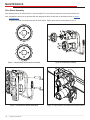
Drive Wheel Assembly
Drive wheel assembly for AdvanceDrive™ and XtremeDrive™ is the same because they use the same wheel hub.
Note: Installation instructions are provided with the replacement drive wheels and are accessible online at support.
hysecurity.com.
A quick look at the drive wheel assembly is shown below. Tighten drive wheel mounting bolts to 18 ft-lb.
Figure 7. AdvanceDrive and XtremeDrive Wheels Figure 8. AdvanceDrive Wheels
Figure 9. AdvanceDrive Wheels assembled Figure 10. AdvanceDrive and XtremeDrive Wheel combo
MAINTENANCE

19
MX5385 Rev. B ©2023
HYDRAULIC SYSTEM MAINTENANCE
Fluid Level:
be added:
1. Remove the metal plug from the reservoir.
2.
by our distributors.
3. Fill to within ½ in of the plug level, and then replace plug.
MAINTENANCE
NOTICE
recommended by HySecurity may void the operator
warranty.
Look for leaks:
To Change Fluid:
caused by heat is the main concern. If the unit is subjected to high use, or you are using the HySecurity biodegradable
1. Remove the reservoir from the pump pack.
2. Completely empty it.
3. Wipe the reservoir clean and clean the debris screen.
4.
5.
of the port’s opening.
6.
Cold Weather Issues:
1.
2. Excessive ice buildup can partially or totally jam gate operation. Operate the gate manually, while clearing the ice
buildup.
3. If the operator is located in an area of extreme snow conditions, regular maintenance to dig the operator out may be
required. A heater option is recommended.
Pump pack
reservoir
Quick
Disconnect
Brake
Valves
Directional
Valve
Unloader
Valve

20 support.hysecurity.com
Brake Valves
For SlideDriver II operators with adjustable brake valves proper adjustment of the brake valves is important for smooth
operation of the gate (not all SlideDriver II operators have adjustable brake valves). The position and placement of the
Adjustment of the brake valves, one for each direction of travel, will determine how quickly the gate actually stops. If
each incremental turn.
Pressure Relief Valve
DO NOT adjust the pressure relief valve. The pressure relief valve governs the maximum system hydraulic pressure. It is
located on the backside of the pump. The pressure relief valve is factory set.
Unloader Valve
Only on the SlideDriver II 15 and 40. Allows the motor to start with no hydraulic load.
Directional Valve
of this valve is possible or necessary. The black solenoid coil mounts on its valve stem.
MAINTENANCE
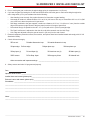
La page est en cours de chargement...
La page est en cours de chargement...
La page est en cours de chargement...
La page est en cours de chargement...
La page est en cours de chargement...
La page est en cours de chargement...
La page est en cours de chargement...
La page est en cours de chargement...
La page est en cours de chargement...
La page est en cours de chargement...
La page est en cours de chargement...
La page est en cours de chargement...
La page est en cours de chargement...
La page est en cours de chargement...
La page est en cours de chargement...
La page est en cours de chargement...
-
 1
1
-
 2
2
-
 3
3
-
 4
4
-
 5
5
-
 6
6
-
 7
7
-
 8
8
-
 9
9
-
 10
10
-
 11
11
-
 12
12
-
 13
13
-
 14
14
-
 15
15
-
 16
16
-
 17
17
-
 18
18
-
 19
19
-
 20
20
-
 21
21
-
 22
22
-
 23
23
-
 24
24
-
 25
25
-
 26
26
-
 27
27
-
 28
28
-
 29
29
-
 30
30
-
 31
31
-
 32
32
-
 33
33
-
 34
34
-
 35
35
-
 36
36


HySecurity SlideDriver II Mode d'emploi
- Catégorie
- Ouvre-porte
- Taper
- Mode d'emploi
dans d''autres langues
- English: HySecurity SlideDriver II User guide
Autres documents
-
 Nice HySecurity SlideSmart CNX Slide Gate Operator Guide d'installation
-
Nice TITAN12L1 Manuel utilisateur
-
CAME Frog-A 24U Guide d'installation
-
-
-
 Mighty Mule FM502 Guide d'installation
-
 RIB AA14041 Manuel utilisateur
-
Chamberlain HC400ML-2 Le manuel du propriétaire
-
-
LiftMaster LMWEKITU Manuel utilisateur


