Zephyr AK9134AS-BF Hood User Manual
- Catégorie
- Hottes
- Taper
- Hood User Manual

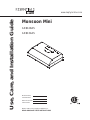
Use, Care, and Installation Guide
www.zephyronline.com
Model number:
Serial Number:
Date of Purchase:
Sales Dealer:
MAR17.0301 © 2017 Zephyr Ventilation LLC.
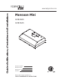
Monsoon Mini
AK9128AS
AK9134AS
READ AND SAVE THESE INSTRUCTIONS

www.zephyronline.com

1
SAFETY NOTICE .......................................................................... 2-3
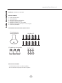
LIST OF MATERIALS
................................................................. 4
INSTALLATION
Ducting Calculation Sheet
....................................... 5
Mounting Height & Clearance
................................ 6
Ducting Options
........................................................... 7
6SHFL¿FDWLRQV
............................................................... 8
Electrical
......................................................................... 9
Cabinet Preparation & Installation
....................... 10
Ducting Preparation
................................................... 11
Recirculation Option
.................................................. 12
FEATURES & CONTROLS
Slide Controls
............................................................... 13
MAINTENANCE
Cleaning and Installing Filters
............................... 14
Lights
................................................................................ 15
TROUBLESHOOTING
................................................................ 16
WIRING DIAGRAMS
................................................................... 17
LIST OF PARTS AND ACCESSORIES
.............................. 18
WARRANTY
.................................................................................... 19
PRODUCT REGISTRATION
.................................................... 20
Table of Contents

Important Safety Notice
READ AND SAVE THESE INSTRUCTIONS
2
www.zephyronline.com
WARNING
TO REDUCE THE RISK OF FIRE OR ELECTRIC SHOCK, DO NOT USE THIS FAN WITH ANY SOLID-STATE CONTROL DEVICE.
WARNING
TO REDUCE THE RISK OF FIRE ELECTRIC SHOCK, OR INJURY TO PERSONS, OBSERVE THE FOLLOWING:
a. Use this unit only in the manner intended by the manufacturer, if you have questions, contact the manufacturer.
b. Before servicing or cleaning unit, switch power off at service panel and lock panel to prevent power from being switched on accidentally.
When the service disconnecting means cannot be locked, securely fasten a prominent warning device, such as a tag, to the service
panel.
CAUTION
For general ventilating use only. Do not use to exhaust hazardous or explosive materials and vapors. Take care when using cleaning
agents or detergents. Suitable for use in household cooking area.
WARNING
TO REDUCE THE RISK OF RANGE TOP GREASE FIRE:
a. Never leave surface units unattended at high settings. Boilovers cause smoking and greasy spillovers that may ignite. Heat oils slowly
on low or medium settings.
E $OZD\VWXUQKRRG21ZKHQFRRNLQJDWKLJKKHDWRUZKHQÀDPLQJIRRG
F &OHDQYHQWLODWLQJIDQVIUHTXHQWO\*UHDVHVKRXOGQRWEHDOORZHGWRDFFXPXODWHRQIDQRU¿OWHU
d. Use proper pan size. Always use cookware appropriate for the size of the surface element.
H .HHSIDQ¿OWHUVDQGJUHDVHODGHQVXUIDFHVFOHDQ
f. Use high setting on hood only when necessary.
g. Don’t leave hood unattended when cooking.
h. Always use cookware and utensils appropriate for the type of and amount of food being prepared.
WARNING
TO REDUCE THE RISK OF INJURY TO PERSONS IN THE EVENT OF A RANGE TOP FIRE, OBSERVE THE FOLLOWING:
D 6027+(5)/$0(6ZLWKDFORVH¿WWLQJOLGFRRNLHVKHHWRUPHWDOWUD\WKHQWXUQRIIWKHEXUQHU%(&$5()8/7235(9(17%8516
,IWKHÀDPHVGRQRWJRRXWLPPHGLDWHO\(9$&8$7($1'&$//7+(),5('(3$570(17
b. NEVER PICK UP A FLAMING PAN – You may be burned.
c. DO NOT USE WATER, including wet dishcloths or towels – a violent steam explosion will result.
d. Use an extinguisher ONLY if:
1. You know you have a Class ABC extinguisher, and you already know how to operate it.
7KH¿UHLVVPDOODQGFRQWDLQHGLQWKHDUHDZKHUHLWVWDUWHG
7KH¿UHGHSDUWPHQWLVEHLQJFDOOHG
<RXFDQ¿JKWWKH¿UHZLWK\RXUEDFNWRDQH[LW
WARNING
TO REDUCE THE RISK OF FIRE, ELECTRIC SHOCK OR INJURY TO PERSONS, OBSERVE THE FOLLOWING:
D ,QVWDOODWLRQZRUNDQGHOHFWULFDOZLULQJPXVWEHGRQHE\TXDOL¿HGSHUVRQVLQDFFRUGDQFHZLWKDOODSSOLFDEOHFRGHVDQGVWDQGDUGV
,QFOXGLQJ¿UHUDWHGFRQVWUXFWLRQ
E 6XI¿FLHQWDLULVQHHGHGIRUSRZHUFRPEXVWLRQDQGH[KDXVWLQJRIJDVHVWKURXJKWKHÀXHFKLPQH\RIIXHOEXUQLQJHTXLSPHQWWRSUHYHQW
back-drafting. Follow the heating equipment manufacturer’s guideline and safety standards such as those published by the National
)LUH3URWHFWLRQ$VVRFLDWLRQ1)3$DQGWKH$PHULFDQ6RFLHW\IRU+HDWLQJ5HIULJHUDWLRQDQG$LU&RQGLWLRQLQJ(QJLQHHUV$6+5$(DQG
the local code authorities.
c. When cutting or drilling into wall or ceiling, do not damage electrical wiring and other hidden utilities.
d. Ducted fans must always vent to the outdoors.
e. NEVER place a switch where it can be reached from a tub or shower.
f. Make sure the power is off before installing, wiring or maintenancing.

Important Safety Notice
3
WARNING
TO REDUCE THE RISK OF FIRE, USE ONLY METAL DUCTWORK.
NOT FOR USE OVER AN OUTDOOR GRILL
CAUTION
7RUHGXFHULVNRI¿UHDQGWRSURSHUO\H[KDXVWDLURXWVLGH'RQRWYHQWH[KDXVWDLULQWRVSDFHVZLWKLQZDOOVFHLOLQJV
attics, crawl spaces or garages.
OPERATION
$OZD\VOHDYHVDIHW\JULOOHVDQG¿OWHUVLQSODFH:LWKRXWWKHVHFRPSRQHQWVRSHUDWLQJEORZHUVFRXOGFDWFKRQWRKDLU¿QJHUV
and loose clothing.
The manufacturer declines all responsibility in the event of failure to observe the instructions given here for installation,
maintenance and suitable use of the product. The manufacturer further declines all responsibility for injury due to
negligence and the warranty of the unit automatically expires due to improper maintenance.
*NOTE: Please check www.zephyronline.com for revisions before doing any custom work.
ELECTRICAL REQUIREMENTS
Important:
Observe all governing codes and ordinances.
It is the customer’s responsibility:
7RFRQWDFWDTXDOL¿HGHOHFWULFDOLQVWDOOHU
- To assure that the electrical installation is adequate and in conformance with National Electrical Code, ANSI/NFPA 70
latest edition* or CSA standards C22.1-94, Canadian Electrical Code, Part 1 and C22.2 No.0-M91 - latest edition** and
all local codes and ordinances.
,IFRGHVSHUPLWDQGDVHSDUDWHJURXQGZLUHLVXVHGLWLVUHFRPPHQGHGWKDWDTXDOL¿HGHOHFWULFLDQGHWHUPLQHWKDWWKH
ground path is adequate.
Do not ground to a gas pipe.
&KHFNZLWKDTXDOL¿HGHOHFWULFLDQLI\RXDUHQRWVXUHWKHUDQJHKRRGLVSURSHUO\JURXQGHG
Do not have a fuse in the neutral or ground circuit.
*National Fire Protection Association Batterymarch Park, Quincy, Massachusetts 02269
** CSA International 8501 East Pleasant Valley Road, Cleveland, Ohio 44131-5575
This appliance requires a 120V 60Hz electrical supply and connected to an individual properly grounded branch circuit
protected by a 15 or 20 ampere circuit breaker or time delay fuse. Wiring must be 2 wire with ground. Please also refer to
Electrical Diagram on product.
AK9128AS / AK9134AS - 177W, 1.5 Amps
$FDEOHORFNLQJFRQQHFWRUQRWVXSSOLHGPLJKWDOVREHUHTXLUHGE\ORFDOFRGHV&KHFNZLWKORFDOUHTXLUHPHQWVSXUFKDVH
and install appropriate connector if necessary.

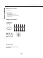
List of Materials
4
www.zephyronline.com
MODELS: AK9128AS AND AK9134AS
PARTS SUPPLIED
1 - Liner hood body
$OXPLQXPPHVK¿OWHUV
+DORJHQOLJKWEXOEVSUHLQVWDOOHG
1 - 7” round adaptor
1 - 3 1/4” x 10” rectangular adaptor w/damper
1 - Hardware package
HARDWARE PACKAGE CONTENTS
PARTS NOT SUPPLIED
- Ducting, conduit and all installation tools
- Cable connector (if required by local codes)
- Recirculating kit
Light Bulb Removal
Suction Cup (1)
M4 x 6mm (6)
Wire Caps (3)
#8 x 1/2” (12)

5
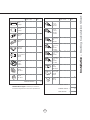
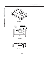
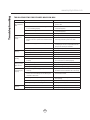
Installation – Ducting Calculation Sheet
Duct pieces
Tot a l
Equivalent number
length x used =
3- 1/4” x 10”
Rect.,
straight
1 Ft. x ( ) =
Ft.
3- 1/4” x 10”
Rect. to
6” round
transition
5 Ft. x ( ) =
Ft.
3- 1/4” x 10”
Rect. to
6” round
transition
90
0
elbow
20 Ft. x ( ) =
Ft.
6”, 7”, 8”, 10”
Round,
90
0
15 Ft.
x ( ) =
Ft.
6”, 7”, 8”, 10”
Round,
45
0
9 Ft. x ( ) =
Ft.
Ft.
6”, 7”, 8”, 10”
Round,
straight
1 Ft. x ( ) =
Ft.
Subtotal column 1 =
Duct pieces
Tot a l
Equivalent number
length x used =
6”, 7”, 8”, 10”
Round, wall
cap with
damper
30 Ft. x ( ) =
Ft.
Ft.
Ft.
Ft.
6”, 7”, 8”, 10”
Round
roof cap
30 Ft. x ( ) =
Ft.
Subtotal column 2 =
Subtotal column 1 =
Total ductwork =
Maximum Duct Length: For satisfactory air movement,
the total duct length
should not exceed 100 equivalent feet.
6” round to
3- 1/4” x 10”
rect.
transition
1 Ft. x ( ) =
Ft.
6” round to
3- 1/4” x 10”
rect.
transition
90
0
elbow
16 Ft. x ( ) =
Ft.
7” round to
3 1/4” x 10”
rect.
transition
8 Ft. x ( ) =
Ft.
7” round to
3- 1/4” x 10”
rect.
transition
90
0
elbow
23 Ft. x ( ) =
Ft.
elbow
elbow
7” to 6” or
8” to 7” Round
tapered
reducer
25 Ft. x ( ) =
Ft.
3- 1/4” x 10”
Rect. 90
0
elbow
15 Ft. x ( ) =
Ft.
3- 1/4” x 10”
Rect. 45
0
elbow
9 Ft. x ( ) =
Ft.
3- 1/4” x 10”
Rect. 90
0
flat elbow
24 Ft. x ( ) =
Ft.
3- 1/4” x 10”
Rect.
wall cap
with damper
30 Ft. x ( ) =
Ft.
Ft. x ( ) =
Ft.
15
6”, 7“, 8”
Round
in-line
damper

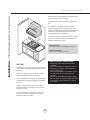
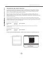
Installation – Mounting Height & Clearance
6
www.zephyronline.com
DUCTING
A minimum of 7” round or 3-1/4” x 10” rectangular
GXFWPXVWEHXVHGWRPDLQWDLQPD[LPXPDLUÀRZ
HI¿FLHQF\
Always use rigid type metal ducts only. Flexible
GXFWVFRXOGUHVWULFWDLUÀRZE\XSWR
$OVRXVHFDOFXODWLRQRQSDJHWRFRPSXWHWRWDO
available duct run when using elbows, transitions
and caps.
ALWAYS, when possible, reduce the number or
transitions and turns. If long duct run is required,
increase duct size.
If turns or transitions are required; install as far
away from hood duct output and as far apart,
between the two as possible.
Minimum mount height between range top to hood
bottom should be no less than 26”.
Maximum mount height should be no higher than
36”.
It is important to install the hood at the proper
mounting height. Hoods mounted too low could
UHVXOWLQKHDWGDPDJHDQG¿UHKD]DUGZKLOHKRRGV
mounted too high will be hard to reach and will
ORVHLWVSHUIRUPDQFHDQGHI¿FLHQF\
If available, also refer range manufacturer’s height
clearance requirements and recommended hood
mounting height above range.
Vertical Ducting:
7” round or 3 1/4” x 10” rectangular minimum
Horizontal Ducting:
3 1/4” x 10” rectangular minimum
DAMAGE-SHIPMENT / INSTALLATION:
3OHDVHIXOO\LQVSHFWXQLWIRUGDPDJHEHIRUH
installation.
,IWKHXQLWLVGDPDJHGLQVKLSPHQWUHWXUQWKH
unit to the store in which it was bought for
repair or replacement.
,IWKHXQLWLVGDPDJHGE\WKHFXVWRPHUUHSDLU
or replacement is the responsibility of the
customer.
,IWKHXQLWLVGDPDJHGE\WKHLQVWDOOHULIRWKHU
WKDQWKHFXVWRPHUUHSDLURIUHSODFHPHQWPXVW
be made by arrangement between customer
and installer.
26” min.
36” max.
36”

7
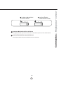
WARNING FIRE HAZARD
NEVER exhaust air or terminate duct work into spaces between walls, crawl spaces, ceiling, attics or garages.
All exhaust must be ducted to the outside.
Use single wall rigid metal ductwork only.
)DVWHQDOOFRQQHFWLRQVZLWKVKHHWPHWDOVFUHZVDQGWDSHDOOMRLQWVZLWKFHUWL¿HG6LOYHU7DSHRU'XFW7DSH
Some Ducting Options
Installation – Ducting Options
side wall cap
w/ gravity damper
side wall cap
w/ gravity dampe
r
Soffit or crawl space
Roof Pitch w/
Flashing & Cap
3-1/4”x10” rect.
horizontal ducting
7” round
vertical ducting
7” round
vertical ducting

8
www.zephyronline.com
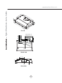
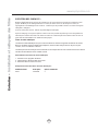
Installation – 6SHFL¿FDWLRQV
Top View
3/4 View
Back View
C/L
6 1/8”
1
8
-
1/
1
6
”
26-
3/16
”, 3 2
-3/16
”
1
3”
3”
28-
3/8
”, 34-
3/8
”
2”
(28”)14-
1/4
”
(34“)17-
1/4
”
1-
1/2
”
8-
3/4
”
C/L
2-
1/2
”
4-
3/4
”
Ø
6-
3
/
4
”
3-
1
/
4”
x1
0
”
elec.
k/o
8-
3/4
”
4-
7/8
”
4”

9
ELECTRICAL
WARNING
$OO(OHFWULFDOZRUNPXVWEHSHUIRUPHGE\TXDOL¿HGHOHFWULFLDQRUSHUVRQZLWKVLPLODUWHFKQLFDONQRZ
how and background.
For personal safety, remove house fuse or open circuit breaker before beginning installation. Do not use
extension cord or adapter plug with this appliance.
Follow national electrical codes or prevailing local codes and ordinances.
Electrical Supply:
This appliance requires a 120V 60Hz electrical supply, and connected to an individual, properly grounded
branch circuit, protected by a 15 or 20 ampere circuit breaker or time delay fuse. Wiring must be 2 wire w/
ground. Please also refer Electrical Diagram labeled on product.
Cable Lock:
$FDEOHORFNLQJFRQQHFWRUQRWVXSSOLHGPLJKWDOVREHUHTXLUHGE\ORFDOFRGHV&KHFNZLWKORFDOUHTXLUHPHQWV
and codes, purchase and install appropriate connector if necessary.
Installation – Electrical
Cable Lock

10
www.zephyronline.com
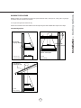
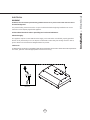
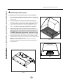
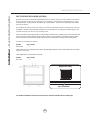
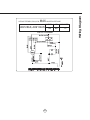
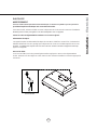
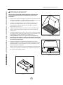
Installation – Cabinet Preparation & Installation
5HPRYHDOOSDFNLQJPDWHULDOVDQGSURWHFWLYH¿OPSULRUWRLQVWDOODWLRQ
Use caution during installation to prevent scratches or damage to the
stainless steel.
2. Cut out an opening in the bottom of the cabinet by following the
dimensions in FIG. 1. If ducting the one piece liner horizontally, also
FXWRXWDQRSHQLQJLQWKHEDFNRIWKHFDELQHWLIDSSOLFDEOH),*
3. Prepare liner for installation into cabinet by following the steps on
page 11. Continue to Step 4 after preparation is completed.
4. Lift liner into bottom opening of cabinet and secure to interior of
FDELQHWXVLQJ[´VWDLQOHVVVWHHOVFUHZVVFUHZVLQWKH
IURQWDQGVFUHZVLQWKHVLGHVDQGVFUHZVLQWKHEDFN),*
WARNING: Make sure the surface you are securing the liner to
is capable of holding the weight of AK91. Failure to do so may
cause personal injury or damage to cooking surface or counter.
5. Finalize installation of electrical and duct work. Seal duct work with
FHUWL¿HGDOXPLQXPGXFWWDSH3RZHURQOLQHUFKHFNIRUOHDNVDURXQG
duct tape and verify proper operation.
NOTE: If access to top of liner is not available after installation,
electrical and duct work connection may need to be made prior to
installing the liner.
CAUTION: At least two installers are required
due to the weight and size of the liner.
!
If possible, power up and test all functions prior to installation.
28-
1/
2
” or
34-
1
/2
”
18-
1/
4
”
c
ut
out
(AK9128)
(AK9134)
4”
11”
4”
C/L
CABINET BACK
3-1/4in x 10in Rectangular
FIG. 1
FIG. 2
1/4”
3/4”
3/4”
FIG. 3

11
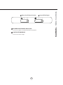
Installation – Ducting Preparation
Note: If using hood in recirculating mode skip these steps and turn to page 12.
Vertical Ducting
5RXQG
Vertical Ducting
[5HFWDQJXODU
8VLQJDÀDWKHDGVFUHZGULYHUUHPRYHERWKWKH
rectangular and round knock-out plates located on
top of hood
8VLQJDÀDWKHDGVFUHZGULYHUUHPRYHRQO\WKH
rectangular section of the knock-out plate located
on top of hood.
8VLQJDÀDWKHDGVFUHZGULYHUUHPRYHWKH
rectangular knock-out plate located on back of
hood.
6HFXUH[UHFWDQJXODUFROODUWRWRSRI
KRRGXVLQJ0[VFUHZV
6HFXUH[UHFWDQJXODUFROODUWREDFNRI
KRRGXVLQJ0[VFUHZV
6HFXUHURXQGFROODUWRWRSRIKRRGXVLQJ
0[VFUHZV
Horizontal Ducting
[5HFWDQJXODU
16
25
34
1
6
2
5
3
4
1
6
2
5
3
4

12
www.zephyronline.com
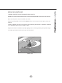
Installation – Recirculation Option
DUCTLESS RECIRCULATING (OPTION)
Ductless recirculating is intended for applications where an exhaust duct work is not possible to be installed.
When converted, the one piece liner functions in air “purifying” mode rather than exhausting the air. Fumes
DQGH[KDXVWIURPFRRNLQJLVGUDZQDQG¿OWHUHGE\DFKDUFRDO¿OWHU7KHDLULVWKHQSXUL¿HGDQGUHFLUFXODWHG
back into the kitchen.
We recommend to always exhaust air outside of the home by employing existing or installing new duct work,
LISRVVLEOH7KHOLQHULVPRVWHIIHFWLYHDQGHI¿FLHQWDVDQH[KDXVWXQLW2QO\ZKHQWKHH[KDXVWRSWLRQLVQRW
possible should you use the liner in recirculating mode.
:KHQFRQYHUWHGWRUHFLUFXODWLQJPRGHDFKDUFRDO¿OWHULVUHTXLUHGWREHLQVWDOOHGRQWRSRIWKHPHVK¿OWHUDQG
DUHWXUQDLUYHQWLVQHHGHGWRGLUHFWDLUEDFNLQWRWKHNLWFKHQ7KHPHVK¿OWHULVLQWHQGHGWRFDSWXUHUHVLGXH
IURPFRRNLQJDQGWKHFKDUFRDO¿OWHUKHOSVWRSXULI\IXPHVH[KDXVWHGIURPFRRNLQJLQUHFLUFXODWLQJPRGH
Purchase recirculating kit as follows.
Part No. Qty. to Order
ZRC-9100A 1
&KDUFRDO¿OWHUVDUHQRWZDVKDEOHDQGPXVWEHUHSODFHGDSSUR[LPDWHO\HYHU\PRQWKVEDVHGRIIDQDYHUDJH
usage of 1 hour a day.
2UGHUUHSODFHPHQWFKDUFRDO¿OWHUVDVIROORZV
Part No. Qty. to Order
Z0F-C091 2
For detailed installation instructions please refer to manual included with recirculating kit.
Return Air Vent
top of cabinet

13
0 I II III
Blower On/Off Speed Selection
1
Lights Off/Dim/Bright
2
0 I II
BLOWER ON/OFF/SPEED SELECTION
0 is off, I is low speed, II is medium speed and III is high speed.
LIGHTS OFF/DIM/BRIGHT
0 is off, I is dim, and II is bright.
1
2
Controls – Slide Controls

14
www.zephyronline.com
SURFACE MAINTENANCE:
Clean the hood surface periodically with hot soapy water and clean cotton cloth. Do not use corrosive or abrasive
detergent, or steel wool/scouring pads which will scratch and damage surface. Do not use products containing
chlorine bleach or orange cleaners.
For heavier soil use liquid degreaser.
After cleaning, you may use non-abrasive stainless steel polish/ cleaners, to polish and buff out the stainless
OXVWHUDQGJUDLQ$OZD\VVFUXEOLJKWO\XVLQJDPLFUR¿EHURUFOHDQFRWWRQFORWKDQGZLWKJUDLQ
Aluminum Mesh Filters
7KHDOXPLQXPPHVK¿OWHUVDUHLQWHQGHGWRWUDSUHVLGXHDQGJUHDVHIURPFRRNLQJ$OWKRXJKWKHDOXPLQXPPHVK
¿OWHUVVKRXOGQHYHUQHHGUHSODFLQJWKH\DUHUHTXLUHGWREHFOHDQHGHYHU\GD\VRUPRUHRIWHQGHSHQGLQJRQ
cooking habits.
)LOWHUVPD\EHSODFHGLQGLVKZDVKHUDWORZKHDWRUVRDNHGLQKRWVRDS\ZDWHU'U\¿OWHUVDQGUHLQVWDOOEHIRUH
using hood.
Removing Aluminum Mesh Filters
3XVKLQRQVSULQJORDGHG¿OWHUKDQGOH
3XOOGRZQRQ¿OWHUKDQGOHWRUHPRYH¿OWHU
Replacing Aluminum Mesh Filters
Hood Model: Part No. Qty. to Order.
All models and sizes 50200059 2
Maintenance – Cleaning and Installing Filters

15
REPLACING LIGHT BULBS
CAUTION: Light bulb becomes extremely hot when turned on.
DO NOT touch bulb until switched off and cooled. Touching hot bulbs could cause serious burns.
Make sure all power is turned off and bulbs are not hot.
Remove by turning bulb counter clockwise. Note: Bulb does not unscrew; it turns 60 degrees, stops and
falls out.
,IEXOEVDUHGLI¿FXOWWRWXUQGXHWRSURORQJHGXVH¿UPO\DWWDFKWKHJODVVVXFWLRQFXSSURYLGHGWRWKHEXOERU
use a rubber/latex glove and turn counter clockwise.
5HSODFHPHQWEXOEVDUHDYDLODEOHDWVSHFLDOW\OLJKWLQJVWRUHV3XUFKDVHW\SH05*8:KDORJHQ
For Zephyr part numbers please turn to page 18 of the manual.
Maintenance – Lights
Bottom View

16
www.zephyronline.com
Troubleshooting
TROUBLESHOOTING PROCEDURES MONSOON MINI
Issue Cause What to do
After installation,
the unit doesn’t
work.
1. The power source is not turned ON. 1. Make sure the circuit breaker and the unit’s
power is ON.
2. The power line and the cable locking connector
is not connecting properly.
2. Check the power connection with the unit is
connected properly.
3. The switch wirings are disconnected. 3. Make sure the wirings at the switch are
connected properly.
4. The switch is defective. 4. Change the switch.
Light works, but
blower is not
turning.
1. The blower is defective, possible seized. 1. Change the blower.
2. The thermally protected system detects if the
blower is too hot to operate and shuts the blower
down.
2. The blower will function properly after the
thermally protected system cools down.
3. Blower molex plug pin is not making contact. 3. Disconnect the blower molex plug, check pins
inside plug to see if one is pushed inside the
plug too far. Reseat pin if needed.
4. Damaged capacitor. 4. Change the capacitor.
The unit is
vibrating.
1. The blower is not secure in place. 1. Tighten the blower in place.
2. Damaged blower wheel. 2. Change the blower.
3. The hood is not secured in place. 3. Check the installation of the hood.
The unit is
whistling.
7KH¿OWHULVQRWLQWKHFRUUHFWSRVLWLRQ &KDQJHWKHSRVLWLRQRIWKH¿OWHU
2. The duct pipe connections are not connected
properly.
2. Check the duct pipe connections to be sure all
are connections are sealed properly.
The blower is
working, but the
lights are not.
1. Defective halogen bulb. 1. Change the halogen bulb.
2. The light bulb is loose. 2. Tighten the light bulb.
3. The light bulb plug is disconnected. 3. Connect the light bulb plug.
The hood is
not venting out
properly.
1. The hood might be hanging to high from the
cook top.
1. Adjust the distance between the cook top and
the bottom of the hood within 26” to 36” range.
2. The wind from the opened windows or opened
doors in the surrounding area are affecting the
ventilation of the hood.
2. Close all the windows and doors to eliminate
WKHRXWVLGHZLQGÀRZ
3. Blocking in the duct opening or duct work. 3. Remove all the blocking from the duct work or
duct opening.
4. The direction of duct opening is against the wind. 4. Adjust the duct opening direction.
5. Using the wrong size of ducting. 5. Change the ducting to at least 7” or higher.
0HWDO¿OWHULV
vibrating.
0HWDO¿OWHULVORRVH &KDQJHWKHPHWDO¿OWHU
2. Spring clip is broken. 2. Change the spring clip.

17
VOLTS
HZ
MAX AMPS
120
60
USE ONLY TYPE MR16, GU10, 35 W.
MAX.
HALOGEN LIGHT BULBS.
CIRCUIT DIAGRAM
AK9128AS, AK9134AS
1.5
Wiring Diagram

18
www.zephyronline.com
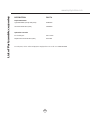
DESCRIPTION PART #
Replacement Parts
/LJKW%XOE05*8:HDFK =%
$OXPLQXP0HVK)LOWHUHDFK
Optional Accessories
Recirculating Kit ZRC-9100A
5HSODFHPHQW&KDUFRDO)LOWHUHDFK =)&
To order parts, visit us online at http://store.zephyronline.com or call us at 1.888.880.8368
List of Parts and Accessories
La page est en cours de chargement...
La page est en cours de chargement...
La page est en cours de chargement...
La page est en cours de chargement...
La page est en cours de chargement...
La page est en cours de chargement...
La page est en cours de chargement...
La page est en cours de chargement...
La page est en cours de chargement...
La page est en cours de chargement...
La page est en cours de chargement...
La page est en cours de chargement...
La page est en cours de chargement...
La page est en cours de chargement...
La page est en cours de chargement...
La page est en cours de chargement...
La page est en cours de chargement...
La page est en cours de chargement...
La page est en cours de chargement...
La page est en cours de chargement...
La page est en cours de chargement...
La page est en cours de chargement...
La page est en cours de chargement...
La page est en cours de chargement...
-
 1
1
-
 2
2
-
 3
3
-
 4
4
-
 5
5
-
 6
6
-
 7
7
-
 8
8
-
 9
9
-
 10
10
-
 11
11
-
 12
12
-
 13
13
-
 14
14
-
 15
15
-
 16
16
-
 17
17
-
 18
18
-
 19
19
-
 20
20
-
 21
21
-
 22
22
-
 23
23
-
 24
24
-
 25
25
-
 26
26
-
 27
27
-
 28
28
-
 29
29
-
 30
30
-
 31
31
-
 32
32
-
 33
33
-
 34
34
-
 35
35
-
 36
36
-
 37
37
-
 38
38
-
 39
39
-
 40
40
-
 41
41
-
 42
42
-
 43
43
-
 44
44


Zephyr AK9134AS-BF Hood User Manual
- Catégorie
- Hottes
- Taper
- Hood User Manual
dans d''autres langues
- English: Zephyr AK9134AS-BF
Documents connexes
-
Zephyr ZPI-E36AG290 Manuel utilisateur
-
-
-
-
Zephyr ZGE-E30AS290 Manuel utilisateur
-
Essentials ZPIE30AG290 Le manuel du propriétaire
-
-
-
-