Miller COOL RUNNER 3CS Le manuel du propriétaire
- Catégorie
- Système de soudage
- Taper
- Le manuel du propriétaire
Ce manuel convient également à

OWNER’S MANUAL
OM‐230 161B
2008-03
Cool Runner 3CS™
1. Specifications
Recirculating Coolant System For Water-Cooled GTAW Torches And GMAW Guns
Use With Guns/Torches Rated Up To 400 Amperes
3 gal (11.4 L) Coolant Tank Capacity; Flow Rate Is 1 Liter Per Minute (1.1 Quarts)
Cooling Unit Dimensions: 25-5/8 in (651 mm) Long, 19-13/16 in (503 mm) Wide, 10-3/4 in (273 mm) High;
Weight, 40 lb (18Kg)
Base Dimensions: 25-15/16 in (659 mm) Long, 22-1/4 in (565 mm) Wide, 11-15/16 in (659 mm) High
115 Volt Models Use 5.9 Amperes, 50/60 Hertz, Single-Phase Input Power
IP Rating: 23
2. Safety Symbol Definitions
DANGER! − Indicates a hazardous situation which, if not
avoided, will result in death or serious injury. The possible
hazards are shown in the adjoining symbols or explained
in the text.
DANGER! − Indique une situation dangereuse qui si on
l’évite pas peut donner la mort ou des blessures graves.
Les dangers possibles sont montrés par les symboles
joints ou sont expliqués dans le texte.
Wear safety glasses with side shields.
Porter des lunettes de sécurité avec des protections laté-
rales.
Indicates a hazardous situation which, if not avoided,
could result in death or serious injury. The possible ha-
zards are shown in the adjoining symbols or explained in
the text.
Indique une situation dangereuse qui si on l’évite pas peut
donner la mort ou des blessures graves. Les dangers possi-
bles sont montrés par les symboles joints ou sont expliqués
dans le texte.
Have only trained and qualified persons install, operate,
or service this unit. Call your distributor if you do not un-
derstand the directions. For WELDING SAFETY and
EMF information, read owner’s manual(s).
L’installation, l’exploitation et l’entretien de cet appareil
doivent être confiés uniquement à des personnes quali-
fiées et convenablement formées. S’adresser à un distri-
buteur si l’on ne comprend pas les directives. Pour les
renseignements ayant trait à la SECURITE lors du sou-
dage et aux champs électromagnétiques, consulter les
manuels traitant les dévidoirs et les sources de courant
pour le soudage.
NOTICE
Indicates statements not related to personal injury.
Indique des déclarations pas en relation avec des blessu-
res personnelles.
Indicates special instructions.
Indique des instructions spécifiques.
Beware of moving parts. Keep guards and panels in
place, covers closed, and hands away from moving parts.
Attention aux pièces mobiles. Maintenir les dispositifs de
sécurité et les panneaux en place, les couvercles fermés
et garder les mains éloignées des pièces mobiles.
Beware of electric shock from wiring. Disconnect input
power before installing this kit. Reinstall all panels and
covers.
Prendre garde aux chocs électriques dus au câblage.
Avant d’installer cet ensemble, couper l’alimentation.
Réinstaller tous les panneaux et couvercles.
Recycle or dispose of used coolant in an environmentally
safe way.
Recycler ou éliminer tout liquide de refroidissement usé
conformément aux méthodes prescrites pour assurer la
protection de l’environnement.

OM-230 161 Page 2
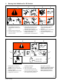
3. Warning Label Definitions For CE Products
S-180 663
1 2 3 4 5
6
7 8 9
1 Warning! Watch Out! There are
possible hazards as shown by the
symbols.
2 Electric shock from wiring can kill.
3 Disconnect input plug or power before
working on machine.
4 Moving parts, such as fans, can cut
fingers and hands and cause injury.
Keep away from moving parts.
5 Wear safety glasses with side shields.
6 Read the Owner’s Manual before
working on this machine.
7 Read the labels on the welding power
source, wire feeder, or other major
equipment for welding safety
information.
8 Recycle or dispose of used coolant in
an environmentally safe way.
9 Do not remove or paint over (cover)
the label.
4/96
4/96
S-178 910-A
=
043 810 (HF)
043 809 (AL)
100 h. std.
21 3
6
4
7
5
1 Warning! Watch Out! There are
possible hazards as shown by the
symbols.
2 Disconnect input plug or power before
working on machine.
3 Wear safety glasses with side shields.
4 Plugged filter or hoses cause
overheating and damage.
5 Read Owner’s Manual.
6 Check and clean filter every 100
hours; also check condition of hoses.
7 Use Low Conductivity Coolant No. 043
810 for High-Frequency assisted or
Gas Tungsten Arc Welding
applications. Use Aluminum Protecting
Coolant No. 043 810 where coolant
contacts aluminum parts or for Gas
Metal Arc Welding applications or
where High Frequency is not used.

OM-230 161 Page 3
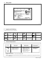
4. Rating Label
231 380-A
5. Symbols And Definitions
. Some symbols are found only on CE products.
A
Amperes Alternating Current
U
1
Primary Voltage Single Phase
V
Volts
Water (Coolant) In-
put
Water (Coolant)
Output
Line Connection
Hz
Hertz
IP
Degree Of
Protection
I
1
Primary Current
6. Coolant Requirements
MILLER Low Conductivity
Coolant No. 043 810**;
Distilled Or Deionized Water
OK Above 32° F (0° C)
MILLER Low Conductivity
Coolant No. 043 810**; Or
MILLER Aluminum Protecting
Coolant No. 043 809**;
Distilled Or Deionized Water
OK Above 32° F (0° C)
GTAW Or Where
HF* Is Used
GMAW Or Where
HF* Is Not Used
Application
*HF: High Frequency Current
**MILLER coolants protect to -37° F (-38°C) and resist algae growth.
Coolant
MILLER Aluminum
Protecting Coolant
No. 043 809**
Where Coolant Contacts
Aluminum Parts
NOTICE − Use of any coolant other than those listed in the table voids the warranty on any parts that come in contact with the coolant (pump,
radiator, etc.).

OM-230 161 Page 4
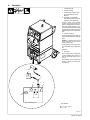
7. Installation
805 139-A
1 Base
Secure base to power source.
2 Bottle Support
3 Chain
Secure bottle support to power
source.
Connect chain to bottle support.
1
2
Tools Needed:
3
3/8 in
9/16 in

OM-230 161 Page 5
8. Operation
805 102-A
1 Coolant Tank Cap
2 Coolant In Fitting
3 Coolant Hose (Customer Sup-
plied - Not Required On All
Models)
4 TIG Block Or International
Style Water Adapter (Customer
Supplied - Varies By Model)
Connect coolant hose between
Coolant In fitting and TIG block lo-
cated on welding power source Elec-
trode weld output terminal, or con-
nect international style water adapter
to Electrode weld output terminal and
adapter water hose to Coolant In fit-
ting.
5 Coolant Out Fitting
Connect hoses between cooling unit
and torch cable/TIG block coolant fit-
tings.
NOTICE − If welding power source
has a water valve, do not connect
hoses to water valve.
See Section 6 to select proper cool-
ant, and fill tank. Keep coolant level
full.
Operation:
6 Flowmeter
To turn cooling unit On, connect pow-
er cord to welding power source 115
volts ac receptacle. Unplug to turn
unit Off.
Flow indicator spins to indicate that
at least 1.1 qt/min (1.0 L/min) of cool-
ant is flowing.
1
3
2
5
6
Front Of Cooling Unit
4
Or
Tools Needed:
11/16 in

OM-230 161 Page 6
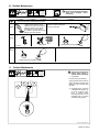
9. Optional Cooler Connections
! Disconnect cooler plug from
welding power source re-
ceptacle before filling.
1 Cap
Remove cap and fill tank with three
gallons of coolant (see Section 6).
2 Gas Out Connection
Connect TIG torch gas hose to gas
out fitting.
3 Electrode Weld Output
Terminal
4 TIG Block (Customer Sup-
plied)
Connect TIG torch to electrode
weld output terminal. Note: Some
models may require a TIG block
instead of the international style
water connector.
5 Remote 14 Receptacle
Connect remote control to recep-
tacle if desired.
6 Work Weld Output Terminal
Connect work lead to work weld
output terminal.
7 Water-In (From Torch)
Connection
Connect torch water-out (red) hose
to welding power source water-in
connection.
NOTICE − If welding power source
has a water valve, do not connect
hoses to water valve.
8 Water-Out (To Torch)
Connection
Connect torch water-in (blue) hose
to welding power source water-out
connection.
Operation:
9 115 VAC Cord
10 Flowmeter
To turn cooling unit On, connect
power cord to welding power
source 115 volts ac receptacle.
Unplug to turn unit Off.
Flow indicator spins to indicate that
at least 1.1 qt/min (1.0 L/min) of
coolant is flowing.
1
3
5
6
7
805 104-A
2
Tools Needed:
11/16 in, (21 mm for CE units)
8
9
4
10

OM-230 161 Page 7
10. Routine Maintenance
! Disconnect cooler plug from welding
power source receptacle before
maintaining.
n = Check Z = Change ~ = Clean Δ = Repair l = Replace
* To be done by Factory Authorized Service Agent
Every
3
Months
~Clean coolant strainer. Severe
conditions may require more frequent
cleaning (continuous use, high/low
temperatures, dirty environment,
etc.). Failure to properly clean coolant
strainer voids pump warranty.
~ Blow out heat exchanger fins.
nCheck coolant level.
Every
6
Months
nlHoses
nl Labels
ZChange coolant if using water.
Every
12
Months
ZChange coolant (if using Miller coolant).
11. Coolant Maintenance
801 195-A / Ref. 801 194
! Disconnect cooler plug from
welding power source re-
ceptacle before maintaining.
1 Coolant Filter
Unscrew housing to clean filter.
Changing coolant: Drain coolant by
tipping unit forward. Fill with clean
water and run for 10 minutes. Drain
and refill.
. If replacing hoses, use hoses
compatible with ethylene gly-
col, such as Buna-n, Neo-
prene, or Hypalon. NOTE:
Oxy-acetylene hoses are not
compatible with any product
containing ethylene glycol.
1

OM-230 161 Page 8
12. Troubleshooting
Trouble Remedy
Coolant system does not work. Be sure input power cord is plugged in to energized receptacle.
Check line fuses or circuit breaker, and replace or reset if necessary.
Motor overheated. Unit starts running when motor has cooled.
Have Factory Authorized Service Agent check motor.
Decreased or no coolant flow. Add coolant.
Check for clogged hoses or coolant filter.
Disconnect pump, and check for sheared coupling. Replace coupling if necessary.
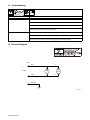
13. Electrical Diagram
225 650-A
BLK
WHT
GRN/YEL
11
12
MOT
PLG1
115VAC.
FM

OM-230 161 Page 9
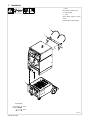
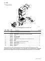
14. Parts
805 100-B
. Hardware is common and
not available unless listed.
1
2
3
4
5
6
7
15
11
12
14
8
9
10
13
Figure 14-1. Running Gear For Cool Runner 3CS
Description
Part
No.
Dia.
Mkgs.
Item
No.
Figure 14-1. Running Gear For Cool Runner 3CS Cooler
Quantity
1 +215 928 Bottle Support 1. . . . . . . . . . . . . . . . . . . . . . . . . . . . . . . . . . . . . . . . . . . . . . . . . . . . . . . . . . . . . . . . . . . .
2 217 140 Label, Warning Cyl May Explode If Damaged (ENG/FR) 1 . . . . . . . . . . . . . . . . . . . . . . . . . . . . . . . . .
3 602 387 Chain 2. . . . . . . . . . . . . . . . . . . . . . . . . . . . . . . . . . . . . . . . . . . . . . . . . . . . . . . . . . . . . . . . . . . . . . . . . . . .
4 168 663 Hook Spring Snap 3. . . . . . . . . . . . . . . . . . . . . . . . . . . . . . . . . . . . . . . . . . . . . . . . . . . . . . . . . . . . . . . . .
5 231 344 Tray Assy, Bottle 1. . . . . . . . . . . . . . . . . . . . . . . . . . . . . . . . . . . . . . . . . . . . . . . . . . . . . . . . . . . . . . . . . . .
6 121 614 Retaining Ring 2. . . . . . . . . . . . . . . . . . . . . . . . . . . . . . . . . . . . . . . . . . . . . . . . . . . . . . . . . . . . . . . . . . . . .
7 602 250 Washer,Flat .812 ID X1.469 OD X.134 T STL PLD ANSI.750 2. . . . . . . . . . . . . . . . . . . . . . . . . . . .
8 209 869 Wheel 2. . . . . . . . . . . . . . . . . . . . . . . . . . . . . . . . . . . . . . . . . . . . . . . . . . . . . . . . . . . . . . . . . . . . . . . . . . . .
9 +233 120 Base 1. . . . . . . . . . . . . . . . . . . . . . . . . . . . . . . . . . . . . . . . . . . . . . . . . . . . . . . . . . . . . . . . . . . . . . . . . . . .
10 230 366 Label, Warning General Precautionary Static 2. . . . . . . . . . . . . . . . . . . . . . . . . . . . . . . . . . . . . . . . . .
11 168 247 Caster, Swivel 2. . . . . . . . . . . . . . . . . . . . . . . . . . . . . . . . . . . . . . . . . . . . . . . . . . . . . . . . . . . . . . . . . . . . .
12 231 336 Cool Unit, 3CS (See Figure 14-2) 1. . . . . . . . . . . . . . . . . . . . . . . . . . . . . . . . . . . . . . . . . . . . . . . . . . . .
13 233 121 Beam, Caster 1. . . . . . . . . . . . . . . . . . . . . . . . . . . . . . . . . . . . . . . . . . . . . . . . . . . . . . . . . . . . . . . . . . . .
14 196 312 Guard,Fan 1. . . . . . . . . . . . . . . . . . . . . . . . . . . . . . . . . . . . . . . . . . . . . . . . . . . . . . . . . . . . . . . . . . . . . . .
15 235 506 Spacer 2. . . . . . . . . . . . . . . . . . . . . . . . . . . . . . . . . . . . . . . . . . . . . . . . . . . . . . . . . . . . . . . . . . . . . . . . . .
+When ordering a component originally displaying a precautionary label, the label should also be ordered.
To maintain the factory original performance of your equipment, use only Manufacturer’s Suggested
Replacement Parts. Model and serial number required when ordering parts from your local distributor.

OM-230 161 Page 10
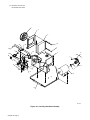
. Hardware is common and
not available unless listed.
1
2
3
6
7
9
7
10
8
11
12
13
14
15
16
17
18
19
20
21
22
23
28
25
26
7
27
24
29
30
4
5
804 995-A
Figure 14-2. Cooling Unit Main Assembly

OM-230 161 Page 11
Figure 14-2. Cooling Unit Main Assembly
Description Quantity
Part
No.
Item
No.
1 213072 Fan, Muffin 115 V 60 Hz 3400 RPM 6.378 Mtg Holes 1. . . . . . . . . . . . . . . . . . . . . . . . . . . . . . . . .
2 231341 Plenum, Air 1. . . . . . . . . . . . . . . . . . . . . . . . . . . . . . . . . . . . . . . . . . . . . . . . . . . . . . . . . . . . . . . . . . . . .
3 232424 Radiator, Heat Exchanger 1. . . . . . . . . . . . . . . . . . . . . . . . . . . . . . . . . . . . . . . . . . . . . . . . . . . . . . . .
4 232842 Hose, Rubber Braided .375 ID X .650 OD X 28.000 2. . . . . . . . . . . . . . . . . . . . . . . . . . . . . . . . . .
5 232609 Hose, Rubber Braided .375 ID X .650 OD X 31.000 2. . . . . . . . . . . . . . . . . . . . . . . . . . . . . . . . . .
6 200109 Tank, Coolant 1. . . . . . . . . . . . . . . . . . . . . . . . . . . . . . . . . . . . . . . . . . . . . . . . . . . . . . . . . . . . . . . . . . .
7 231400 Hose, Rubber Braided .375 ID X .650 OD X 17.000 3. . . . . . . . . . . . . . . . . . . . . . . . . . . . . . . . . .
8 174042 Pump, Coolant (Includes) 1. . . . . . . . . . . . . . . . . . . . . . . . . . . . . . . . . . . . . . . . . . . . . . . . . . . . . . . .
9 5523 FTG, Hose Brs Barbed Elbow M 3/8 TBG X 3/8 NPT 2. . . . . . . . . . . . . . . . . . . . . . . . . . . . . . . . . .
10 134795 Coupler, Drive Pump 1. . . . . . . . . . . . . . . . . . . . . . . . . . . . . . . . . . . . . . . . . . . . . . . . . . . . . . . . . . . .
11 023562 Clamp, Hose .312 − .875 Clp Dia 1. . . . . . . . . . . . . . . . . . . . . . . . . . . . . . . . . . . . . . . . . . . . . . . . . .
12 173263 Motor, 1/4 Hp 115 VAC 50/60 Hz 1425/1725 RPM Dual 1. . . . . . . . . . . . . . . . . . . . . . . . . . . . . . .
13 231337 Base, 1. . . . . . . . . . . . . . . . . . . . . . . . . . . . . . . . . . . . . . . . . . . . . . . . . . . . . . . . . . . . . . . . . . . . . . . . .
14 232413 Label, Rating Card CSA C US (Less Stock/Serial No) 1. . . . . . . . . . . . . . . . . . . . . . . . . . . . . . . .
15 231340 Panel, Front Component 1. . . . . . . . . . . . . . . . . . . . . . . . . . . . . . . . . . . . . . . . . . . . . . . . . . . . . . . . .
16 204604 Label, Coolant In 1. . . . . . . . . . . . . . . . . . . . . . . . . . . . . . . . . . . . . . . . . . . . . . . . . . . . . . . . . . . . . . . .
17 149356 Ftg, Hose Brs Barbed Elbow M Bhd 3/8 Tbg X .500−20 2. . . . . . . . . . . . . . . . . . . . . . . . . . . . . .
18 204603 Label, Coolant Out 1. . . . . . . . . . . . . . . . . . . . . . . . . . . . . . . . . . . . . . . . . . . . . . . . . . . . . . . . . . . . . .
226934 Indicator, Flow (Includes) 1. . . . . . . . . . . . . . . . . . . . . . . . . . . . . . . . . . . . . . . . . . . . . . . . . . . . . . . . . . . .
19 186005 Lense, Flow Indicator 1. . . . . . . . . . . . . . . . . . . . . . . . . . . . . . . . . . . . . . . . . . . . . . . . . . . . . . . . . . .
20 166566 O−Ring, 1.301 ID X .070 CS 70 Duro Buna−n1. . . . . . . . . . . . . . . . . . . . . . . . . . . . . . . . . . . . . .
21 226 936 Paddle, Rotor Assy 1. . . . . . . . . . . . . . . . . . . . . . . . . . . . . . . . . . . . . . . . . . . . . . . . . . . . . . . . . . . . .
22 226935 Housing, Flow Indicator 1. . . . . . . . . . . . . . . . . . . . . . . . . . . . . . . . . . . . . . . . . . . . . . . . . . . . . . . . .
23 143797 Spacer, Nylon .312 OD X .194 ID X .437 Lg 2. . . . . . . . . . . . . . . . . . . . . . . . . . . . . . . . . . . . . . . .
24 178461 Bracket, Filter 1. . . . . . . . . . . . . . . . . . . . . . . . . . . . . . . . . . . . . . . . . . . . . . . . . . . . . . . . . . . . . . . . . . .
25 139042 Bushing, Strain Relief .270/.470 ID X .804 mtg Hole 1. . . . . . . . . . . . . . . . . . . . . . . . . . . . . . . . .
26 188082 Cable, Power 2 Ft 7 In 16 ga 3c 1. . . . . . . . . . . . . . . . . . . . . . . . . . . . . . . . . . . . . . . . . . . . . . . . . . .
27 232621 Tube, Pick−Up Coolant 1. . . . . . . . . . . . . . . . . . . . . . . . . . . . . . . . . . . . . . . . . . . . . . . . . . . . . . . . . . .
28 231339 Panel, Front Filler 1. . . . . . . . . . . . . . . . . . . . . . . . . . . . . . . . . . . . . . . . . . . . . . . . . . . . . . . . . . . . . . .
29 166564 Filter, In−line Low Profile 100 Screen 3/8 Hose Bar 1. . . . . . . . . . . . . . . . . . . . . . . . . . . . . . . . . .
225113 Harness, 3CS Cooler (Not Shown) 1. . . . . . . . . . . . . . . . . . . . . . . . . . . . . . . . . . . . . . . . . . . . . . . . . . . .
141727 Tubing, Gl Acryl .750− .786 ID 4.000 Yel Fa1 (Not Shown) 2. . . . . . . . . . . . . . . . . . . . . . . . . . . . . . .
30 166608 Cap, Tank Screw−On W/Vent 1. . . . . . . . . . . . . . . . . . . . . . . . . . . . . . . . . . . . . . . . . . . . . . . . . . . . .
To maintain the factory original performance of your equipment, use only Manufacturer’s Suggested
Replacement Parts. Model and serial number required when ordering parts from your local distributor.
BE SURE TO PROVIDE MODEL AND SERIAL NUMBER WHEN ORDERING REPLACEMENT PARTS.

PRINTED IN USA © 2008 Miller Electric Mfg. Co.2007−01
Miller Electric Mfg. Co.
An Illinois Tool Works Company
1635 West Spencer Street
Appleton, WI 54914 USA
International Headquarters−USA
USA Phone: 920-735-4505 Auto-Attended
USA & Canada FAX: 920-735-4134
International FAX: 920-735-4125
European Headquarters −
United Kingdom
Phone: 44 (0) 1204-593493
FAX: 44 (0) 1204-598066
www.MillerWelds.com
Model Name Serial/Style Number
Purchase Date (Date which equipment was delivered to original customer.)
Distributor
Address
City
State Zip
Please complete and retain with your personal records.
Always provide Model Name and Serial/Style Number.
Contact a DISTRIBUTOR or SERVICE AGENCY near you.
Welding Supplies and Consumables
Options and Accessories
Personal Safety Equipment
Service and Repair
Replacement Parts
Training (Schools, Videos, Books)
Technical Manuals (Servicing Information
and Parts)
Circuit Diagrams
Welding Process Handbooks
Contact the Delivering Carrier to:
For Service
Owner’s Record
File a claim for loss or damage during
shipment.
For assistance in filing or settling claims, contact
your distributor and/or equipment manufacturer’s
Transportation Department.
Contact your Distributor for:
To locate a Distributor or Service Agency visit
www.millerwelds.com or call 1-800-4-A-Miller
-
 1
1
-
 2
2
-
 3
3
-
 4
4
-
 5
5
-
 6
6
-
 7
7
-
 8
8
-
 9
9
-
 10
10
-
 11
11
-
 12
12


Miller COOL RUNNER 3CS Le manuel du propriétaire
- Catégorie
- Système de soudage
- Taper
- Le manuel du propriétaire
- Ce manuel convient également à
dans d''autres langues
Documents connexes
-
Miller MA330202L Le manuel du propriétaire
-
-
-
-
-
Miller Coolmate 1 Le manuel du propriétaire
-
-
-
-