Lincoln Electric Red-D-Arc D503K 5-3 Mode d'emploi
- Catégorie
- Système de soudage
- Taper
- Mode d'emploi

RED-D-ARC
D503K 5+3 HO
IM694
February, 2001
Red-D-Arc Spec-Built Welding Equipment
This RED-D-ARC welder is built to RED-D-ARC Extreme Duty
design specifications by Lincoln Electric.
Safety Depends on You
This welder is designed and built with safety in mind.
However, your overall safety can be increased by proper installation
... and thoughtful operation on your part.
DO NOT INSTALL, OPERATE OR REPAIR THIS EQUIPMENT
WITHOUT READING THIS MANUAL AND THE SAFETY
PRECAUTIONS CONTAINED THROUGHOUT.
And, most importantly, think before you act and be careful.
For use with machines having Code Numbers:
10748
North America’s Largest Fleet of Welding Equipment
1-800-245-3660
OPERATOR’S MANUAL

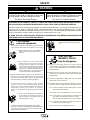
FOR ENGINE
powered equipment.
1.a. Turn the engine off before troubleshooting and maintenance
work unless the maintenance work requires it to be running.
____________________________________________________
1.b. Operate engines in open, well-ventilated
areas or vent the engine exhaust fumes
outdoors.
____________________________________________________
1.c. Do not add the fuel near an open flame
welding arc or when the engine is running.
Stop the engine and allow it to cool before
refueling to prevent spilled fuel from vaporiz-
ing on contact with hot engine parts and
igniting. Do not spill fuel when filling tank. If
fuel is spilled, wipe it up and do not start
engine until fumes have been eliminated.
____________________________________________________
1.d. Keep all equipment safety guards, covers and devices in
position and in good repair.Keep hands, hair, clothing and
tools away from V-belts, gears, fans and all other moving
parts when starting, operating or repairing equipment.
____________________________________________________
1.e. In some cases it may be necessary to remove safety
guards to perform required maintenance. Remove
guards only when necessary and replace them when the
maintenance requiring their removal is complete.
Always use the greatest care when working near moving
parts.
___________________________________________________
1.f. Do not put your hands near the engine fan.
Do not attempt to override the governor or
idler by pushing on the throttle control rods
while the engine is running.
___________________________________________________
1.g. To prevent accidentally starting gasoline engines while
turning the engine or welding generator during maintenance
work, disconnect the spark plug wires, distributor cap or
magneto wire as appropriate.
i
SAFETY
i
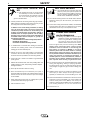
ARC WELDING CAN BE HAZARDOUS. PROTECT YOURSELF AND OTHERS FROM POSSIBLE SERIOUS INJURY OR DEATH.
KEEP CHILDREN AWAY. PACEMAKER WEARERS SHOULD CONSULT WITH THEIR DOCTOR BEFORE OPERATING.
Read and understand the following safety highlights. For additional safety information, it is strongly recommended that you
purchase a copy of “Safety in Welding & Cutting - ANSI Standard Z49.1” from the American Welding Society, P.O. Box
351040, Miami, Florida 33135 or CSA Standard W117.2-1974. A Free copy of “Arc Welding Safety” booklet E205 is available
from the Lincoln Electric Company, 22801 St. Clair Avenue, Cleveland, Ohio 44117-1199.
BE SURE THAT ALL INSTALLATION, OPERATION, MAINTENANCE AND REPAIR PROCEDURES ARE
PERFORMED ONLY BY QUALIFIED INDIVIDUALS.
WARNING
Mar ‘95
ELECTRIC AND
MAGNETIC FIELDS
may be dangerous
2.a. Electric current flowing through any conductor causes
localized Electric and Magnetic Fields (EMF). Welding
current creates EMF fields around welding cables and
welding machines
2.b. EMF fields may interfere with some pacemakers, and
welders having a pacemaker should consult their physician
before welding.
2.c. Exposure to EMF fields in welding may have other health
effects which are now not known.
2.d. All welders should use the following procedures in order to
minimize exposure to EMF fields from the welding circuit:
2.d.1.
Route the electrode and work cables together - Secure
them with tape when possible.
2.d.2. Never coil the electrode lead around your body.
2.d.3. Do not place your body between the electrode and
work cables. If the electrode cable is on your right
side, the work cable should also be on your right side.
2.d.4. Connect the work cable to the workpiece as close as
possible to the area being welded.
2.d.5. Do not work next to welding power source.
1.h. To avoid scalding, do not remove the
radiator pressure cap when the engine is
hot.
CALIFORNIA PROPOSITION 65 WARNINGS
Diesel engine exhaust and some of its constituents
are known to the State of California to cause can-
cer, birth defects, and other reproductive harm.
The engine exhaust from this product contains
chemicals known to the State of California to cause
cancer, birth defects, or other reproductive harm.
The Above For Diesel Engines
The Above For Gasoline Engines

ii
SAFETY
ii
ARC RAYS can burn.
4.a. Use a shield with the proper filter and cover
plates to protect your eyes from sparks and
the rays of the arc when welding or observing
open arc welding. Headshield and filter lens
should conform to ANSI Z87. I standards.
4.b. Use suitable clothing made from durable flame-resistant
material to protect your skin and that of your helpers from
the arc rays.
4.c. Protect other nearby personnel with suitable, non-flammable
screening and/or warn them not to watch the arc nor expose
themselves to the arc rays or to hot spatter or metal.
ELECTRIC SHOCK can
kill.
3.a. The electrode and work (or ground) circuits
are electrically “hot” when the welder is on.
Do not touch these “hot” parts with your bare
skin or wet clothing. Wear dry, hole-free
gloves to insulate hands.
3.b. Insulate yourself from work and ground using dry insulation.
Make certain the insulation is large enough to cover your full
area of physical contact with work and ground.
In addition to the normal safety precautions, if welding
must be performed under electrically hazardous
conditions (in damp locations or while wearing wet
clothing; on metal structures such as floors, gratings or
scaffolds; when in cramped positions such as sitting,
kneeling or lying, if there is a high risk of unavoidable or
accidental contact with the workpiece or ground) use
the following equipment:
• Semiautomatic DC Constant Voltage (Wire) Welder.
• DC Manual (Stick) Welder.
• AC Welder with Reduced Voltage Control.
3.c. In semiautomatic or automatic wire welding, the electrode,
electrode reel, welding head, nozzle or semiautomatic
welding gun are also electrically “hot”.
3.d. Always be sure the work cable makes a good electrical
connection with the metal being welded. The connection
should be as close as possible to the area being welded.
3.e. Ground the work or metal to be welded to a good electrical
(earth) ground.
3.f.
Maintain the electrode holder, work clamp, welding cable and
welding machine in good, safe operating condition. Replace
damaged insulation.
3.g. Never dip the electrode in water for cooling.
3.h. Never simultaneously touch electrically “hot” parts of
electrode holders connected to two welders because voltage
between the two can be the total of the open circuit voltage
of both welders.
3.i. When working above floor level, use a safety belt to protect
yourself from a fall should you get a shock.
3.j. Also see Items 6.c. and 8.
FUMES AND GASES
can be dangerous.
5.a. Welding may produce fumes and gases
hazardous to health. Avoid breathing these
fumes and gases.When welding, keep
your head out of the fume. Use enough
ventilation and/or exhaust at the arc to keep
fumes and gases away from the breathing zone. When
welding with electrodes which require special
ventilation such as stainless or hard facing (see
instructions on container or MSDS) or on lead or
cadmium plated steel and other metals or coatings
which produce highly toxic fumes, keep exposure as
low as possible and below Threshold Limit Values (TLV)
using local exhaust or mechanical ventilation. In
confined spaces or in some circumstances, outdoors, a
respirator may be required. Additional precautions are
also required when welding on galvanized steel.
5.b.
Do not weld in locations near chlorinated hydrocarbon
vapors
coming from degreasing, cleaning or spraying operations.
The heat and rays of the arc can react with solvent vapors
to
form phosgene, a highly toxic gas, and other irritating prod-
ucts.
5.c. Shielding gases used for arc welding can displace air and
cause injury or death. Always use enough ventilation,
especially in confined areas, to insure breathing air is safe.
5.d. Read and understand the manufacturer’s instructions for this
equipment and the consumables to be used, including the
material safety data sheet (MSDS) and follow your
employer’s safety practices. MSDS forms are available from
your welding distributor or from the manufacturer.
5.e. Also see item 1.b.
Mar ‘95

FOR ELECTRICALLY
powered equipment.
8.a. Turn off input power using the disconnect
switch at the fuse box before working on
the equipment.
8.b. Install equipment in accordance with the U.S. National
Electrical Code, all local codes and the manufacturer’s
recommendations.
8.c. Ground the equipment in accordance with the U.S. National
Electrical Code and the manufacturer’s recommendations.
CYLINDER may explode
if damaged.
7.a. Use only compressed gas cylinders
containing the correct shielding gas for the
process used and properly operating
regulators designed for the gas and
pressure used. All hoses, fittings, etc. should be suitable for
the application and maintained in good condition.
7.b. Always keep cylinders in an upright position securely
chained to an undercarriage or fixed support.
7.c. Cylinders should be located:
• Away from areas where they may be struck or subjected to
physical damage.
• A safe distance from arc welding or cutting operations and
any other source of heat, sparks, or flame.
7.d. Never allow the electrode, electrode holder or any other
electrically “hot” parts to touch a cylinder.
7.e. Keep your head and face away from the cylinder valve outlet
when opening the cylinder valve.
7.f. Valve protection caps should always be in place and hand
tight except when the cylinder is in use or connected for
use.
7.g. Read and follow the instructions on compressed gas
cylinders, associated equipment, and CGA publication P-l,
“Precautions for Safe Handling of Compressed Gases in
Cylinders,” available from the Compressed Gas Association
1235 Jefferson Davis Highway, Arlington, VA 22202.
iii
SAFETY
iii
Mar ‘95
WELDING SPARKS can
cause fire or explosion.
6.a.
Remove fire hazards from the welding area.
If this is not possible, cover them to prevent
the welding sparks from starting a fire.
Remember that welding sparks and hot
materials from welding can easily go through small cracks
and openings to adjacent areas. Avoid welding near
hydraulic lines. Have a fire extinguisher readily available.
6.b. Where compressed gases are to be used at the job site,
special precautions should be used to prevent hazardous
situations. Refer to “Safety in Welding and Cutting” (ANSI
Standard Z49.1) and the operating information for the
equipment being used.
6.c. When not welding, make certain no part of the electrode
circuit is touching the work or ground. Accidental contact
can cause overheating and create a fire hazard.
6.d. Do not heat, cut or weld tanks, drums or containers until the
proper steps have been taken to insure that such procedures
will not cause flammable or toxic vapors from substances
inside. They can cause an explosion even
though
they have
been “cleaned”. For information, purchase “Recommended
Safe Practices for the
Preparation
for Welding and Cutting of
Containers and Piping That Have Held Hazardous
Substances”, AWS F4.1 from the American Welding Society
(see address above).
6.e. Vent hollow castings or containers before heating, cutting or
welding. They may explode.
6.f.
Sparks and spatter are thrown from the welding arc. Wear oil
free protective garments such as leather gloves, heavy shirt,
cuffless trousers, high shoes and a cap over your hair. Wear
ear plugs when welding out of position or in confined places.
Always wear safety glasses with side shields when in a
welding area.
6.g. Connect the work cable to the work as close to the welding
area as practical. Work cables connected to the building
framework or other locations away from the welding area
increase the possibility of the welding current passing
through lifting chains, crane cables or other alternate cir-
cuits. This can create fire hazards or overheat lifting chains
or cables until they fail.
6.h. Also see item 1.c.

iv
SAFETY
iv
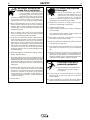
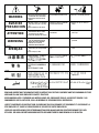
PRÉCAUTIONS DE SÛRETÉ
Pour votre propre protection lire et observer toutes les instructions
et les précautions de sûreté specifiques qui parraissent dans ce
manuel aussi bien que les précautions de sûreté générales suiv-
antes:
Sûreté Pour Soudage A L’Arc
1. Protegez-vous contre la secousse électrique:
a. Les circuits à l’électrode et à la piéce sont sous tension
quand la machine à souder est en marche. Eviter toujours
tout contact entre les parties sous tension et la peau nue
ou les vétements mouillés. Porter des gants secs et sans
trous pour isoler les mains.
b. Faire trés attention de bien s’isoler de la masse quand on
soude dans des endroits humides, ou sur un plancher
metallique ou des grilles metalliques, principalement dans
les positions assis ou couché pour lesquelles une grande
partie du corps peut être en contact avec la masse.
c. Maintenir le porte-électrode, la pince de masse, le câble
de soudage et la machine à souder en bon et sûr état
defonctionnement.
d.Ne jamais plonger le porte-électrode dans l’eau pour le
refroidir.
e. Ne jamais toucher simultanément les parties sous tension
des porte-électrodes connectés à deux machines à souder
parce que la tension entre les deux pinces peut être le
total de la tension à vide des deux machines.
f. Si on utilise la machine à souder comme une source de
courant pour soudage semi-automatique, ces precautions
pour le porte-électrode s’applicuent aussi au pistolet de
soudage.
2. Dans le cas de travail au dessus du niveau du sol, se protéger
contre les chutes dans le cas ou on recoit un choc. Ne jamais
enrouler le câble-électrode autour de n’importe quelle partie
du corps.
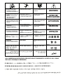
3. Un coup d’arc peut être plus sévère qu’un coup de soliel,
donc:
a. Utiliser un bon masque avec un verre filtrant approprié
ainsi qu’un verre blanc afin de se protéger les yeux du ray-
onnement de l’arc et des projections quand on soude ou
quand on regarde l’arc.
b. Porter des vêtements convenables afin de protéger la
peau de soudeur et des aides contre le rayonnement de
l‘arc.
c. Protéger l’autre personnel travaillant à proximité au
soudage à l’aide d’écrans appropriés et non-inflammables.
4. Des gouttes de laitier en fusion sont émises de l’arc de
soudage. Se protéger avec des vêtements de protection libres
de l’huile, tels que les gants en cuir, chemise épaisse, pan-
talons sans revers, et chaussures montantes.
5. Toujours porter des lunettes de sécurité dans la zone de
soudage. Utiliser des lunettes avec écrans lateraux dans les
zones où l’on pique le laitier.
6. Eloigner les matériaux inflammables ou les recouvrir afin de
prévenir tout risque d’incendie dû aux étincelles.
7. Quand on ne soude pas, poser la pince à une endroit isolé de
la masse. Un court-circuit accidental peut provoquer un
échauffement et un risque d’incendie.
8. S’assurer que la masse est connectée le plus prés possible
de la zone de travail qu’il est pratique de le faire. Si on place
la masse sur la charpente de la construction ou d’autres
endroits éloignés de la zone de travail, on augmente le risque
de voir passer le courant de soudage par les chaines de lev-
age, câbles de grue, ou autres circuits. Cela peut provoquer
des risques d’incendie ou d’echauffement des chaines et des
câbles jusqu’à ce qu’ils se rompent.
9. Assurer une ventilation suffisante dans la zone de soudage.
Ceci est particuliérement important pour le soudage de tôles
galvanisées plombées, ou cadmiées ou tout autre métal qui
produit des fumeés toxiques.
10. Ne pas souder en présence de vapeurs de chlore provenant
d’opérations de dégraissage, nettoyage ou pistolage. La
chaleur ou les rayons de l’arc peuvent réagir avec les vapeurs
du solvant pour produire du phosgéne (gas fortement toxique)
ou autres produits irritants.
11. Pour obtenir de plus amples renseignements sur la sûreté,
voir le code “Code for safety in welding and cutting” CSA
Standard W 117.2-1974.
PRÉCAUTIONS DE SÛRETÉ POUR
LES MACHINES À SOUDER À
TRANSFORMATEUR ET À
REDRESSEUR
1. Relier à la terre le chassis du poste conformement au code de
l’électricité et aux recommendations du fabricant. Le dispositif
de montage ou la piece à souder doit être branché à une
bonne mise à la terre.
2. Autant que possible, I’installation et l’entretien du poste seront
effectués par un électricien qualifié.
3. Avant de faires des travaux à l’interieur de poste, la debranch-
er à l’interrupteur à la boite de fusibles.
4. Garder tous les couvercles et dispositifs de sûreté à leur
place.
Mar. ‘93

Thank You
for selecting a QUALITY product. We want you to take pride in
operating this product ••• as much pride as we have in bringing
this product to you!
Read this Operators Manual completely before attempting to use this equipment. Save this manual and keep it
handy for quick reference. Pay particular attention to the safety instructions we have provided for your protection.
The level of seriousness to be applied to each is explained below:
WARNING
This statement appears where the information must be followed exactly to avoid serious personal injury or
loss of life.
This statement appears where the information must be followed to avoid minor personal injury or damage to
this equipment.
CAUTION
Please Examine Carton and Equipment For Damage Immediately
When this equipment is shipped, title passes to the purchaser upon receipt by the carrier. Consequently, Claims
for material damaged in shipment must be made by the purchaser against the transportation company at the
time the shipment is received.
Please record your equipment identification information below for future reference. This information can be
found on your machine nameplate.
Model Name & Number _____________________________________
Code & Serial Number _____________________________________
Date of Purchase _____________________________________
Whenever you request replacement parts for or information on this equipment always supply the information
you have recorded above.
vv

D503K 5+3 HO
vi
vi
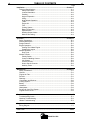
TABLE OF CONTENTS
Page
Installation .......................................................................................................Section A
Technical Specifications ........................................................................................A-1
Safety Precautions ..........................................................................................A-2
Location/Ventilation.........................................................................................A-2
Stacking ..........................................................................................................A-2
Angle of Operation ..........................................................................................A-2
Lifting...............................................................................................................A-2
High Altitude Operation ...................................................................................A-3
Trailer ..............................................................................................................A-3
Engine Oil........................................................................................................A-3
Fuel .................................................................................................................A-3
Cooling System ...............................................................................................A-3
Battery Connection..........................................................................................A-3
Spark Arrester .................................................................................................A-4
Welding Output Cables ...................................................................................A-4
Machine Grounding.........................................................................................A-4
Operation .........................................................................................................Section B
Safety Precautions.................................................................................................B-1
General Description...............................................................................................B-1
Design Features ....................................................................................................B-1
Engine Operation...................................................................................................B-2
Starting The Kubota Engine ............................................................................B-2
Stopping the engine ........................................................................................B-2
Welder Operation...................................................................................................B-2
Duty Cycle.......................................................................................................B-2
Welder Controls.....................................................................................................B-2
Polarity Switch.................................................................................................B-2
Control of Welding Current..............................................................................B-2
Job Selector ....................................................................................................B-2
Current Controls..............................................................................................B-3
How to Set the Controls ..................................................................................B-3
Auxiliary Power ...............................................................................................B-3
Maintenance ....................................................................................................Section D
Safety Precautions ................................................................................................D-1
Routine..................................................................................................................D-1
Engine Air Filter.....................................................................................................D-1
Periodic..................................................................................................................D-1
Bearings ................................................................................................................D-1
Commutator and Brushes .....................................................................................D-2
Cooling System .....................................................................................................D-2
Battery ...................................................................................................................D-2
Hardware...............................................................................................................D-3
Nameplates ...........................................................................................................D-3
Purging Air from Fuel System................................................................................D-3
Engine Service Chart ............................................................................................D-4
Troubleshooting..............................................................................................Section E
Troubleshooting Guide ..........................................................................................E-1
Machine Troubleshooting ......................................................................................E-2
Welder Troubleshooting ........................................................................................E-3
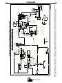
Diagrams ..........................................................................................................Section F
Wiring Diagram .....................................................................................................F-1
Parts Lists................................................................................................................P378

D503K 5+3 HO
TECHNICAL SPECIFICATIONS - Red-D-Arc D503K 5+3 HO
Make/Model Description Speed (RPM) Displacement Starting Capacities
System
Kubota 4 cylinder High Idle 1800 202.5 cu. in
12VDC battery
Fuel: 15 gal.
V3300-EBG-RDA-1-S1
49.5 HP @ Full Load 1740 (3318 cc) 57 L
1800 RPM
4 Cycle Bore x Stroke Oil: 14 Qts.
Water Cooled 13.2 L
Diesel Engine 3.68” x 4.33” Engine Coolant:
(98 mm x 110 mm) 2.5 gal.
9.3 L
INPUT - ENGINE
RATED OUTPUT - WELDER
HEIGHT WIDTH DEPTH WEIGHT
44.43 in. 28.0 in. 71.75 in. 1945 lbs.
1129 mm 711 mm 1822 mm 882 kg.
OUTPUT - GENERATOR
Welding Output Volts at Rated Amps Duty Cycle
1
Max. OCV @ 1800 RPM
400 Amps 40 volts 100% 98 volts DC
Auxiliary Power
2
3,000 Watts, 60 Hz
120 Volts AC
100 % Duty Cycle
PHYSICAL DIMENSIONS
1. Output rating in watts is equivalent to volt-amperes at unity power factor. Output voltage is within ± 10% at all loads up to
rated capacity. When welding, available auxiliary power will be reduced.
A-1
INSTALLATION
A-1

A-2
INSTALLATION
A-2
D503K 5+3 HO
Read this entire installation section before you
start installation.
SAFETY PRECAUTIONS
Do not attempt to use this equipment until you
have thoroughly read all operating and mainte-
nance manuals supplied with your machine. They
include important safety precautions, detailed
engine starting, operating and maintenance
instructions and parts lists.
ELECTRIC SHOCK can kill.
•Do not touch electrically live parts
such as output terminals or internal
wiring.
•Insulate yourself from the work and
ground.
•Always wear dry insulating gloves.
------------------------------------------------------------------------
ENGINE EXHAUST can kill.
•Use in open, well ventilated areas or
vent exhaust outside
•Do not stack anything near the
engine.
------------------------------------------------------------------------
MOVING PARTS can injure.
•Do not operate with doors open or
guards off.
•Stop engine before servicing.
•Keep away from moving parts
------------------------------------------------------------------------
Only qualified personnel should install, use or
service this equipment
LOCATION/VENTILATION
The welder should be located to provide an unrestrict-
ed flow of clean, cool air to the cooling air inlets and to
avoid restricting the cooling air outlets. Also, locate
the welder so that the engine exhaust fumes are prop-
erly vented to an outside area.
STACKING
These machines cannot be stacked.
ANGLE OF OPERATION
To achieve optimum engine performance the machine
should be run in a level position.
LIFTING
The equipment lift bale should be used to lift the
machine.
FALLING EQUIPMENT can cause
injury.
•Do not lift this machine using lift
bale if it is equipped with a heavy
accessory such as a trailer or gas
cylinder.
•Lift only with equipment of adequate
lifting capacity.
•Be sure machine is stable when lift-
ing.
------------------------------------------------------------------------
WARNING
WARNING

A-3
INSTALLATION
A-3
D503K 5+3 HO
HIGH ALTITUDE OPERATION
At higher altitudes, output derating may be necessary.
As a rule of thumb, derate the welder output 5% for
every 500 meters (1640 ft.) above 1000 meters (3280
ft.).
FUEL USE DIESEL FUEL ONLY
•Stop engine and allow to cool before
fueling.
•Do not smoke when fueling.
•Fill fuel tank at a moderate rate and
do not overfill.
•Wipe up spilled fuel and allow fumes
to clear before starting engine.
•Keep sparks and flame away from
tank.
------------------------------------------------------------------------
Fill the fuel tank with clean, fresh diesel fuel. The capaci-
ty of the fuel tank is 15 gallons (57 liters). See engine
Operator’s Manual for specific fuel recommendations.
NOTE:
Before starting the engine, be sure the fuel shut-
off valve is open.
ENGINE COOLING SYSTEM
The cooling system has been filled at the factory with
a 50-50 mixture of ethylene glycol antifreeze and
water. Check the radiator level and add a 50-50 solu-
tion as needed. (See Engine Manual or antifreeze
container for alternate antifreeze recommendation.)
BATTERY CONNECTION
WARNING: Use caution as the electrolyte is a strong
acid that can burn skin and damage eyes.
Remove and discard the insulating caps from the neg-
ative battery terminals. Attach and tighten negative
battery cable terminals.
NOTE:
This machine is furnished with wet charged
batteries; if unused for several months, the batteries
may require a booster charge. Be careful to charge
the batteries with the correct polarity. Make sure that
the batteries are level while charging.
Trailer
If the user adapts a trailer, he must assume responsi-
bility that the method of attachment and usage does
not result in a safety hazard nor damage the welding
equipment. Some of the factors to be considered are
as follows:
1. Design capacity of trailer vs. weight of equipment
and likely additional attachments.
2. Proper support of, and attachment to, the base of
the welding equipment so there will be no undue
stress to the framework.
3. Proper placement of the equipment on the trailer to
ensure stability side to side and front to back when
being moved and when standing by itself while being
operated or serviced.
4. Typical conditions of use, i.e., travel speed, rough-
ness of surface on which the trailer will be operated;
environmental conditions, likely maintenance.
5. Conformance with federal, state and local laws.
(1)
(1)
Consult applicable federal, state and local laws regarding specific
requirements for use on public highways.
ENGINE OIL
The engine is shipped with the engine crankcase filled
with high quality SAE 10W-30 oil (API class CD or bet-
ter). Check the oil level before starting the engine. If it is
not up to the full mark on the dip stick, add oil as
required. Check the oil level every four hours of running
time during the first 35 running hours. Refer to the engine
Operator’s Manual for specific oil recommendations and
break-in information. The oil change interval is dependent
on the quality of the oil and the operating environment.
Refer to the engine Operator’s Manual for the proper ser-
vice and maintenance intervals.
WARNING

GASES FROM BATTERY can explode.
● Keep sparks, flame and cigarettes
away from battery.
To prevent EXPLOSION when:
● INSTALLING A NEW BATTERY — disconnect
negative cable from old battery first and con-
nect to new battery last.
● CONNECTING A BATTERY CHARGER —
remove battery from welder by disconnecting
negative cable first, then positive cable and
battery clamp. When reinstalling, connect
negative cable last. Keep well ventilated.
● USING A BOOSTER — connect positive lead to
battery first then connect negative lead to neg-
ative battery lead at the lower control panel
support.
BATTERY ACID can burn eyes and skin.
● Wear gloves and eye protection
and be careful when working near
battery.
● Follow instructions printed on bat-
tery.
IMPORTANT: To prevent ELECTRICAL DAMAGE
WHEN:
a) Installing new batteries.
b) Using a booster.
Use correct polarity — Negative Ground.
To prevent BATTERY BUCKLING, tighten nuts on
batteries only until snug. DO NOT OVERTIGHTEN.
SPARK ARRESTER
Some federal, state or local laws may require that
gasoline or diesel engines be equipped with exhaust
spark arresters when they are operated in certain
locations where unarrested sparks may present a fire
hazard. The standard muffler included with this welder
does not qualify as a spark arrester. When required by
local regulations, a suitable spark arrester must be
installed and properly maintained.
An incorrect arrester may lead to damage to the
engine or adversely affect performance. Contact
the engine manufacturer for specific recommen-
dations.
------------------------------------------------------------------------
A-4
INSTALLATION
A-4
D503K 5+3 HO
WELDING OUTPUT CABLES
With the engine off, connect the electrode and work
cables to the studs provided. These connections
should be checked periodically and tightened if neces-
sary.
Listed in Table A.1 are copper cable sizes recom-
mended for the rated current and duty cycle. Lengths
stipulated are the distance from the welder to work
and back to the welder again. Cable sizes are
increased for greater lengths primarily for the purpose
of minimizing cable voltage drop.
Table A.1
Combined
Length of Electrode and Work Cables.
MACHINE GROUNDING
Because this portable engine driven welder creates its
own power, it is not necessary to connect its frame to
an earth ground, unless the machine is connected to
premises wiring (home, shop, etc.).
To prevent dangerous electric shock, other equipment
powered by this engine driven welder must:
a) be grounded to the frame of the welder using a
grounded type plug,
or
b) be double insulated.
When this welder is mounted on a truck or trailer, its
frame must be securely connected to the metal frame
of the vehicle. When this engine driven welder is con-
nected to premises wiring such as that in a home or
shop, its frame must be connected to the system earth
ground. See the article on grounding in the latest U.S.
National Electrical Code and the local code.
In general, if the machine is to be grounded, it should
be connected with a #8 or larger copper wire to a solid
earth ground such as a metal water pipe going into
the ground for at least ten feet and having no insulat-
ed joints, or to the metal framework of a building
which has been effectively grounded. The U.S.
National Electrical Code lists a number of alternate
means of grounding electrical equipment. A machine
grounding stud marked with the symbol is provid-
ed on the welding generator frame foot.
Up to 100
FT.
3/0 AWG
100-200 FT.
3/0 AWG
200-250 FT.
4/0 AWG
AMPS
@100%
Duty Cycle
400
TOTAL COMBINED LENGTH OF ELEC-
TRODE AND WORK CABLES
WARNING
CAUTION

B-1B-1
D503K 5+3 HO
SAFETY PRECUATIONS
GENERAL DESCRIPTION
The D503K 5+3 HO is a heavy duty, engine driven,
DC arc welding power source, capable of providing
constant current output for stick welding or DC TIG
welding. This welder is wound with all copper coils,
rated at 400 amps / 40 Volts.
The D503K 5+3 HO has Diesel Engine Protection. In
the event of sudden low oil pressure or high coolant
temperature, the engine immediately shuts down. The
D503K 5+3 HO has a current range of 40-600 DC
amps.
This unit is also capable of providing 3 KVA of 120
volts of 60 hertz AC auxiliary power.
DESIGN FEATURES
CONTROL PANEL
Both the engine and the welder controls are located
on one recessed panel at the exciter end of the
machine. The welder controls consist of an electrode
polarity switch,”Current Control”, and “Job Selector”.
The engine controls consist of a “Start” and “Glow
Plug” switch (for cold weather starts) and a “Stop” pull
knob. Also located on this panel are the engine hour
meter, charging meter, and the engine temperature
gauge.
All Copper Windings - For long life and dependable
operation.
Auxiliary Power - 3.0 KVA of nominal 120V, 60Hz,
AC. Output voltage is maintained within ± 10% at all
loads up to rated capacity.
Welder Enclosure - The complete welder is rubber
mounted on a rugged steel “Box” channel base.
The output terminals are placed at the side of the
machines so that they are protected by the door.
Cranking System - A 12 volt electric starter is stan-
dard.
Air Cleaner - Heavy duty two stage dry type.
Muffler - A muffler and exhaust outlet elbow are stan-
dard.
Engine Hour Meter - A meter to record hours of oper-
ation.
Engine Protection - The system shuts the engine
down in the event of sudden low oil pressure or high
coolant temperature.
Fuel Consumption - Fuel consumption has been
optimized by means of careful design of the combus-
tion chamber, fuel feed and injection system and
cross-flow cylinder heads. In order to enhance
longevity of the engine, the engine turns at a constant
1800 RPM and no engine idler is used.
As a result, there is no waiting time for the welder to
achieve operating speed when striking an arc.
Fuel consumption figures at average operating loads
are as follows:
Tank Capacity: 15 gallons, (57 L)
1.8(gl/hr.)@ 400A @ 40V
1.0(gl/hr.)@ 250A @ 30V
.7(gl/hr.)@ No Load
400A @ 40V 100%
RATED OUTPUT DUTY CYCLE
OPERATION
Do not attempt to use this equipment until you
have thoroughly read the engine manufacturer’s
manual supplied with your welder. It includes
important safety precautions, detailed engine
starting, operating and maintenance instructions,
and parts lists.
------------------------------------------------------------------------
ELECTRIC SHOCK can kill.
• Do not touch electrically live parts or
electrode with skin or wet clothing.
• Insulate yourself from work and
ground
• Always wear dry insulating gloves.
------------------------------------------------------------------------
ENGINE EXHAUST can kill.
• Use in open, well ventilated areas or
vent exhaust outside.
------------------------------------------------------------------------
MOVING PARTS can injure.
• Do not operate with doors open or
guards off.
• Stop engine before servicing.
• Keep away from moving parts.
------------------------------------------------------------------
See additional warning information at the
front of this operator’s manual.
------------------------------------------------------------
WARNING

B-2
OPERATION
B-2
D503K 5+3 HO
ENGINE OPERATION
Operate the welder with the doors closed. Leaving the
doors open changes the designed air flow and can
cause overheating.
STARTING THE D503K 5+3 HO WITH
KUBOTA DIESEL ENGINE
Refer to the Welder Nameplate for starting instruc-
tions.
The D503K 5+3 HO engine is equipped with GLOW
PLUGS. The GLOW PLUGS should always be used
to help start Kubota diesel engines. Follow the table
below for approximate GLOW PLUG on times to be
used prior to attempted starting:
Temperature GLOW PLUGS ON time
Above 32ºF (0ºC) 15 sec.
32ºF to -13ºF (0ºC to -25ºC) 30 sec.
Below -13ºF (-25ºC) 45 sec.
Note: Extreme cold weather starting may require
longer glow plug operation as well as engine oil and
coolant heating (using a block heater).
Under NO
conditions should ether or other
starting fluids be used!
------------------------------------------------------------------------
STOPPING THE ENGINE
1. Pull the “STOP” knob out and hold it out until the
engine stops completely.
At the end of each day’s welding, check the crankcase
oil level, drain accumulated dirt and water from the
sediment bowl under the fuel tank and refill the fuel
tank to minimize moisture condensation in the tank.
Also, running out of fuel tends to draw dirt into the fuel
system.
When moving the welder between job sites, close the
fuel feed valve beneath the fuel tank.
If the fuel supply is cut off or runs out while the fuel
pump is operating, air may be entrapped in the fuel
distribution system. If this happens, bleeding of the
fuel system may be necessary. Use qualified person-
nel to do this per the instructions in the MAINTE-
NANCE section of this manual.
WELDER OPERATION
ELECTRIC SHOCK can kill.
• Do not touch electrically live parts or
electrode with skin or wet clothing.
• Insulate yourself from work and ground.
FUMES & GASES can be dangerous.
• Keep your head out of the fumes.
• Use ventilation or exhaust to remove
fumes from breathing zone.
WELDING SPARKS can cause fire or
explosion.
• Keep flammable material away.
ARC RAYS can burn.
• Wear eye, ear, and body protection.
WARNING
WARNING
DUTY CYCLE
The output rating of the D503K 5+3 HO is 400
amperes at 40 arc volts on
a 100% duty cycle
.
WELDER CONTROLS
POLARITY SWITCH
Turn the Arc Polarity switch to electrode positive or
electrode negative as required for each particular
application.
CONTROL OF WELDING CURRENT
PURPOSE OF CONTROLS
The continuous “Current Control” is the main current
adjuster. The “Job Selector” is both a fine current
adjuster and the continuous Open Circuit Voltage
adjuster. Open Circuit Voltage (OCV) controls the arc
characteristics.
“JOB SELECTOR”
The “Job Selector” dial is divided into four colored
sections providing OCV ranges as follows:
Color Title OCV Range
White Large Electrodes High OCV
Black Normal Welding Medium OCV
Red Overhead & Vertical Low OCV
Grey Special Applications Extra-Low OCV
The “Job Selector” is usually set in the black range
because it provides a soft “Buttering “ arc desired for
most welding. Some operators prefer to set the “Job
Selector” in the red range for a snappy “Digging” arc
when welding vertical up or overhead.

B-3
OPERATION
B-3
AUXILIARY POWER
The AC auxiliary power, supplied as standard, has a
rating of 3.0 kVA of 120 VAC (60 hertz).
With the 3.0 kVA, 120 VAC auxiliary power, one 120V
duplex grounding type receptacle is provided. The cir-
cuit is protected with circuit breakers.
The rating of 3.0 kVA permits a maximum continuous
current of 26 amps that can be drawn from the 120
volt duplex receptacle. The 120 volt duplex receptacle
has a configuration which permits 20 amps to be
drawn from either half. The total combined load of the
duplex receptacle is not to exceed 3.0 kVA.
If auxiliary power is used simultaneously with welding,
the current which can be used while maintaining volt-
age regulation within 10% is as follows:
Welding Using Total
Current Amps 120V Auxiliary
(@ NEMA Circuit, Amps KVA
Arc Volts)
0 26 3.0
100 19.5 2.25
200 13 1.5
300 6.5 0.75
400 0 0
D503K 5+3 HO
“CURRENT CONTROL”
Do not adjust the “Current Control” while welding
because this can damage the control.
-----------------------------------------------------------------------
-
The “Current Control” dial is calibrated in amperes on
three separate colored dials corresponding to the
white, black and red ranges of the “Job Selector” dial.
For example: when the “Job Selector” is set on the
black range, the approximate welding current is indi-
cated on the black scale of the “Current Control” dial.
HOW TO SET THE CONTROLS
Assume you want a normal soft arc and about 135
amps, using a 5/32” (4.0 mm) electrode:
1. Set the “Job Selector” at the center of the black
range.
2. Set the “Current Control” to read 135 amps on
the black dial.
3. Start to weld.
4. If you want a little more current, turn the “Job
Selector” up (counterclockwise) to increase cur-
rent. If you want a little less current, turn the “Job
Selector” down (clockwise) to decrease current.
5. If dialing the desired current with the “Job
Selector” moves the setting outside the black
range causing undesirable arc characteristics,
turn the “Job Selector” back to the center of the
black range. Then turn the “Current Control” up
or down a little as needed. Readjust the “Job
Selector” for the exact characteristics and current
desired.
CAUTION

D-1
MAINTENANCE
D-1
SAFETY PRECAUTIONS
Have qualified personnel do the maintenance
work. Turn the engine off before working inside
the machine. In some cases, it may be
necessary to remove safety guards to perform
required maintenance. Remove guards only
when necessary and replace them when the
maintenance requiring their removal is
complete. Always use the greatest care when
working near moving parts.
Do not put your hands near the engine cooling
blower fan. If a problem cannot be corrected by
following the instructions, take the machine to
the nearest Field Service Shop.
-----------------------------------------------------------------------
ELECTRIC SHOCK can kill.
• Do not touch electrically live parts or
electrode with skin or wet clothing.
• Insulate yourself from work and
ground
• Always wear dry insulating gloves.
------------------------------------------------------------------------
ENGINE EXHAUST can kill.
• Use in open, well ventilated areas or
vent exhaust outside.
------------------------------------------------------------------------
MOVING PARTS can injure.
• Do not operate with doors open or
guards off.
• Stop engine before servicing.
• Keep away from moving parts.
------------------------------------------------------------------------
See additional warning information
throughout this operator’s manual and
the Engine manual as well.
-----------------------------------------------------------
WARNING
ROUTINE MAINTENANCE
At the end of each day’s welding, refill the fuel tank to
minimize moisture condensation in the tank. Also, run-
ning out of fuel tends to draw dirt into the fuel system.
Check the engine crankcase oil levels.
If the fuel supply runs out while the fuel pump is oper-
ating, air may be entrapped in the fuel distribution sys-
tem. If this happens, bleeding of the fuel system may
be necessary. See the engine instruction manual.
ENGINE AIR FILTER
The engine air filter element is a dry cartridge type. It
is located above the engine. It can be cleaned and re-
used; however, damaged elements should not be
washed or re-used. Remove loose dirt from element
with compressed air directed from inside out.
Compressed Air: 100 psi maximum. The filter should
never be removed while the engine is running.
PERIODIC MAINTENANCE
1. Blow out the welder and controls with an air hose at least
once every two months. In particularly dirty locations,
this cleaning may be necessary once a week. Use low
pressure air to avoid driving dirt into the insulation.
2. The current control reactor brushes are self-lubricating
and should not be greased. Keep the contacts clean.
This control should be moved from maximum to mini-
mum daily to prevent the controls from sticking.
3. See the engine Instruction Manual for periodic engine
maintenance information. Change the crankcase oil at
regular intervals using the proper grade of oil as recom-
mended in the engine operating manual. Change the oil
filter in accordance with the instructions in the engine
operating manual.
--------------------------------------------------------------------------------
4. Belts tend to loosen after the first 30 or 40 hours of oper-
ation. Check the cooling fan belt and tighten if neces-
sary. DO NOT OVER TIGHTEN.
BEARING MAINTENANCE
This welder is equipped with a double-shielded ball bearing
having sufficient grease to last indefinitely under normal ser-
vice. Where the welder is used constantly or in excessively
dirty locations, it may be necessary to add one-half ounce of
grease per year. A pad of grease one inch wide, one inch
long and one inch high weighs approximately one-half
ounce. Over greasing is far worse than insufficient greasing.
When greasing the bearings, keep all dirt out of the area.
Wipe the fittings completely clean and use clean equipment.
More bearing failures are caused by dirt introduced during
greasing than from insufficient grease.
WARNING

D-2
MAINTENANCE
D-2
D503K 5+3 HO
COMMUTATOR AND BRUSH MAINTENANCE
Uncovered rotating equipment can be dangerous.
Use care so your hands, hair, clothing or tools do
not catch in the rotating parts. Protect yourself
from particles that may be thrown out by the rotat-
ing armature when stoning the commutator.
------------------------------------------------------------------------
The generator brushes are properly adjusted when
the welder is shipped. They require no particular
attention. DO NOT SHIFT THE BRUSHES or adjust
the rocker setting.
Shifting of the brushes may result in:
- Change in machine output
- Commutator Damage
- Excessive brush wear
Periodically inspect the commutator, slip rings and
brushes by removing the covers. DO NOT remove or
replace these covers while the machine is running.
Commutators and slip rings require little attention.
However, if they are black or appear uneven, have
them cleaned by an experienced maintenance man
using fine sandpaper or a commutator stone. Never
use emery cloth or paper for this purpose.
NOTE: If the welder is used in dirty or dusty locations,
or if the welder is not used for prolonged periods of
time, it may be necessary to clean the commutator
and slip rings more often.
Replace brushes when they wear within 1/4" of the
pigtail. A complete set of replacement brushes should
be kept on hand. Lincoln brushes have a curved face
to fit the commutator. Have an experienced mainte-
nance man seat these brushes by lightly stoning the
commutator as the armature rotates at full speed until
contact is made across the full face of the brushes.
After stoning, blow out the dust with low pressure air.
To seat the slip ring brushes, position the brushes in
place. Then slide one end of a piece of fine sandpaper
between slip rings and brushes with the coarse side
against the brushes. With slight additional finger pres-
sure on top of the brushes, pull the sandpaper around
the circumference of the rings, in direction of rotation
only - until brushes seat properly. In addition, stone
slip ring with a fine stone. Brushes must be seated
100%.
Arcing or excessive exciter brush wear indicates a
possible misaligned shaft. Have an authorized Field
Service Shop check and realign the shaft.
COOLING SYSTEM
The D503K 5+3 HO is equipped with a pressure radia-
tor. Keep the radiator cap tight to prevent loss of
coolant. Clean and flush the cooling system periodi-
cally to prevent clogging the passage and overheating
the engine. When antifreeze is needed, always use
the permanent type.
1. When replacing, jumping, or otherwise connecting
the battery to the battery cables, the proper polarity
must be observed. Failure to observe the proper
polarity could result in damage to the charging cir-
cuit.
2. If the battery requires charging from an external
charger, disconnect the negative battery cable first
and then the positive battery cable before attaching
the charger leads. Failure to do socan result in
damage to the internal charger components. When
reconnecting the cables, connect the positive cable
first and the negative cable last.
WARNING
BATTERY
GASES FROM BATTERY can explode.
• Keep sparks, flame and cigarettes
away from battery.
To prevent EXPLOSION when:
• INSTALLING A NEW BATTERY -
disconnect negative cable from old
battery first and connect to new bat-
tery last.
• CONNECTING A BATTERY CHARG-
ER - Remove battery from welder by
disconnecting negative cable first,
then positive cable and battery
clamp. When reinstalling, connect
negative cable last. Keep well venti-
lated.
• USING A BOOSTER - connect posi-
tive lead to battery first then con-
nect negative lead to engine foot.
BATTERY ACID CAN BURN EYES
AND SKIN.
• Wear gloves and eye protection and
be careful when working near bat-
tery. Follow instructions printed on
battery.
WARNING

D-3
MAINTENANCE
D-3
D503K 5+3 HO
HARDWARE
Both English and Metric fasteners are used in this
welder.
NAMEPLATES
Whenever routine maintenance is performed on this
machine - or at least yearly - inspect all nameplates
and labels for legibility. Replace those which are no
longer clear. Refer to the parts list for the replacement
item number.
PURGING AIR FROM THE FUEL SYSTEM
Keep fuel clear of open flames or arcs, allow
engine to cool before working on the fuel system.
Wipe up any spilled fuel and do not start engine
until fumes clear.
------------------------------------------------------------------------
If the engine is running rough and you suspect air has
been trapped in the fuel system, (EG. the engine was
allowed to run out of fuel) perform the following steps
using qualified personnel:
1. Verify that there is sufficient fuel in the fuel tank.
(Minimum of .50” of fuel).
2. Ensure that the fuel sediment bowl valve is open.
(located on underside of fuel tank).
3. Open the air bleed screw on the fuel injection
pump. Using the starter, crank the engine until
engine starts. (use pre-heat if needed. DO NOT
CRANK STARTER FOR MORE THAN 1 MINUTE
OUT OF 5 MINUTES.
4. Close air bleed screw when fuel is observed
returning to the fuel tank. (Remove fuel cap to
observe).
WARNING

D-4
MAINTENANCE
D-4
D503K 5+3 HO
I
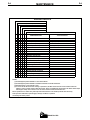
EVERY 400 HOURS OR 12 MONTHS
EVERY 200 HOURS OR 6 MONTHS
EVERY 100 HOURS OR 3 MONTHS
FIRST SERVICE (50 HOURS)
EVERY DAY OR EVERY 8 HOURS
If necessary use shorter periods.
These preventive maintenance periods apply to average conditions of operation.
Kubota- 16631-4356-0
TYPE OR QUANTITY
Above operations to be carried out by trained personnel with reference to the workshop manual where necessary.
Kubota- 1C010-3243-0
(3) Fill slowly! Ensure correct quantity is used.
(4) To remove the air filter element for cleaning or replacement, the filter canister must be moved rearward toward the
radiator in order to provide clearance with the fuel tank. This is accomplished by disconnecting the rubber canister straps
and inlet pipe clamps. The air cleaner cover can then be removed and the element taken out.
14 Qt, (13.2 L)
(2) Consult Engine Operator's Manual for additional maintenance schedule information.
2.5 gal, (9.3 L)
(1) Consult Engine Operator's Manual for oil recommendations.
NOTES:
Alternator drive belt
Kubota- 16521-9701-0
Alternator drive belt wear
R
Tension of alternator drive belt
I
Drain water separator & fuel strainer
Engine oil (NOTE 1 & 3)
R
Engine oil level (NOTE 1)
Coolant (NOTE 3)
MAINTENANCE ITEM
Concentration of antifreeze 50/50 Water/Ethylene Glycol
C
I
R
Coolant level
RR
RR
I
ENGINE SERVICE
I
EVERY 600 HOURS OR 18 MONTHS
Fuel filter canister
Donaldson- P821575
R = ReplaceC = Clean
Battery
Leaks or engine damage
I
Injector performance
All nuts and bolts for tightness
I = Inspect
Electrical systems
I
I
Valve clearances
I
Tighten cylinder head
I
I
Check and adjust idle speed
I
Air filter element
(NOTE 4)
Air filter (earlier check may be req'd.) (NOTE 4)
R
I
C
C
Engine oil filter
ENGINE SERVICE (NOTE 2)

E-1
TROUBLESHOOTING
E-1
If for any reason you do not understand the test procedures or are unable to perform the tests/repairs safely, contact your
Local Lincoln Authorized Field Service Facility for technical troubleshooting assistance before you proceed.
CAUTION
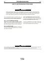
This Troubleshooting Guide is provided to help you
locate and repair possible machine malfunctions.
Simply follow the three-step procedure listed below.
Step 1. LOCATE PROBLEM (SYMPTOM).
Look under the column labeled “PROBLEM (SYMP-
TOMS)”. This column describes possible symptoms
that the machine may exhibit. Find the listing that best
describes the symptom that the machine is exhibiting.
Step 2. POSSIBLE CAUSE.
The second column labeled “POSSIBLE CAUSE” lists
the obvious external possibilities that may contribute
to the machine symptom.
Step 3. RECOMMENDED COURSE OF ACTION
This column provides a course of action for the
Possible Cause, generally it states to contact your
local Lincoln Authorized Field Service Facility.
If you do not understand or are unable to perform the
Recommended Course of Action safely, contact your
local Lincoln Authorized Field Service Facility.
HOW TO USE TROUBLESHOOTING GUIDE
Service and Repair should only be performed by Lincoln Electric Factory Trained Personnel.
Unauthorized repairs performed on this equipment may result in danger to the technician and
machine operator and will invalidate your factory warranty. For your safety and to avoid Electrical
Shock, please observe all safety notes and precautions detailed throughout this manual.
__________________________________________________________________________
WARNING

E-2
TROUBLESHOOTING
E-2
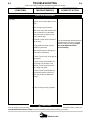
If all recommended possible areas of
misadjustment have been checked
and the problem persists, Contact
your local Authorized Field
Service Facility.
D503K 5+3 HO
If for any reason you do not understand the test procedures or are unable to perform the tests/repairs safely, contact your
Local Authorized Field Service Facility for technical troubleshooting assistance before you proceed.
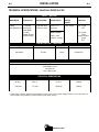
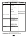
FUNCTION PROBLEMS
Machine fails to hold the “heat”
constantly.
Rough or dirty commutator.
Brushes may be worn down to limit
of life.
Brush springs may be broken.
Field circuit may have variable resis-
tance connections or intermittent
open circuit, due to loose connec-
tions or broken wire.
Electrode or work lead connections
may be poor.
Wrong grade of brushes may be
installed on generator.
Field rheostat may be making poor
contact and overheating.
“Current Control” may not be operat-
ing properly.
“Current Control” brushholder con-
tact springs may be worn out or
missing. Contact surface may be
dirty, rough and pitted.
“Current Control” brushholder sup-
port stud and mating contact sur-
faces may be dirty or pitted and
burned.
Engine running at varying speeds.
Observe all Safety Guidelines detailed throughout this manual
PROBLEMS
(SYMPTOMS)
POSSIBLE AREAS OF
MISADJUSTMENT(S)
RECOMMENDED
COURSE OF ACTION
CAUTION
La page est en cours de chargement...
La page est en cours de chargement...
La page est en cours de chargement...
La page est en cours de chargement...
La page est en cours de chargement...
La page est en cours de chargement...
-
 1
1
-
 2
2
-
 3
3
-
 4
4
-
 5
5
-
 6
6
-
 7
7
-
 8
8
-
 9
9
-
 10
10
-
 11
11
-
 12
12
-
 13
13
-
 14
14
-
 15
15
-
 16
16
-
 17
17
-
 18
18
-
 19
19
-
 20
20
-
 21
21
-
 22
22
-
 23
23
-
 24
24
-
 25
25
-
 26
26


Lincoln Electric Red-D-Arc D503K 5-3 Mode d'emploi
- Catégorie
- Système de soudage
- Taper
- Mode d'emploi
dans d''autres langues
Documents connexes
-
Lincoln Electric Red-D-Arc ZR-10 Mode d'emploi
-
-
-
-
-
-
-
-
-