
PROOFERS
Instruction Manual
AX-PR5 PR8
5659 Royalmount Avenue
Montreal, Qc, Canada H4P 2P9
Tel.: 514.737.9701 / Toll Free: 888.275.4538
Fax.: 514.342.3854 / Toll Free: 877.453.8832
3560 NW 56th Street
Fort Lauderdale, FL 33309
Tel.: 786.600.4687 / Toll Free: 844.218.8477
Fax.: 786.661.4100

E n g l i s h | 1
25/10/2018
CONTENTS: page
INSTRUCTIONS FOR THE INSTALLER
I. WARNINGS 2
II. PRELIMINARY OPERATIONS 2
III. INSTALLATION AREA 3
IV. PREPARING FOR INSTALLATION 3
V. WATER CONNECTION 4
VI. ELECTRICAL CONNECTION 4
VII. SPECIFICATIONS 8
INSTRUCTIONS FOR THE USER
I. WARNINGS 9
II. TESTING 9
III. ORDINARY MAINTENANCE 10
IV. EXTRAORDINARY MAINTENANCE 10
V. MAINTENANCE IN CASE OF BREAKAGE 11
VI. CONTROL PANEL 11
VII. ADVICE DURING COOKING 12

E n g l i s h | 2
INTRODUCTION
Dear customer, thank you and congratulations for buying this appliance; we are confident
that this is the beginning of a positive and long-lasting collaboration.
This manual has all the necessary information for the correct use, maintenance and
installation of this appliance. The objective of this manual is to enable the technician and
user to take all measures and precautions necessary for the safe, efficient, long-term use
of the appliance.
Keep this booklet in a safe place, over the entire life cycle of the product for subsequent
reference by the operators designated to use and specialized technicians.
Where documents are lost or damaged the replacement documentation must be requested
directly from the manufacturer or retailer.
The manufacturer is not held liable for any damage caused by people or things or for
inappropriate use of the appliance, modifications or repairs carried out by unauthorized
personnel or used with spare parts not recommended by the manufacturer and not
intended for use with this model.
This appliance complies with the EEC directives in force.
INSTRUCTIONS FOR THE INSTALLER
I. WARNINGS
Read this instructions booklet carefully before starting the installation and start-up operations.
All installation, assembly, assistance and extraordinary maintenance shall be carried out
by qualified personnel and supplied with necessary professional (authorisations by the
manufacturer or retailer), in accordance with local laws in effect where installation takes
place regarding product and workplace safety.
Incorrect installation, assistance, maintenance, cleaning, tampering or modifications can cause
malfunction, damage and breakage.
The appliance must only be used for cooking or heating of foods in industrial kitchens. Any other
use is inappropriate and dangerous.
II. PRELIMINARY OPERATIONS
On receipt of the product, make sure it has not been damaged during transport and that the
packaging has not been tampered with. In the case of damage or missing parts inform the carrier
and retailer/manufacturer immediately, indicating the code (Art.) and serial number (Ser N°)
and attach a photo.
Check that the installation area is kept clear so that doors, corridors and passageways are
accessible.
WARNING: the appliance may fall over during transport leading to breakage and damage to
things and people. Use suitable transport capable of taking the weight of the appliance. Do not
drag or lean the device for any reason. Lift it up straight from the ground and place horizontally.

E n g l i s h | 3
III. INSTALLATION AREA
The appliance shall be installed in enclosed and well ventilated areas (not outdoors).
Before positioning the appliance, check the overall dimensions and the exact position of the
electrical, water connections.
Make sure that it is placed so that the door may be fully opened.
The appliance is not meant to be fitted and a 2" space must be left all round it.
It is not advised to place it near heat, fryers or other hot liquids. If this is not possible at
least respect the following distances from machinery: 20" from the sides and above the
appliance and 28" from behind.
Do not place the device near materials or containers of inflammable liquids (such as walls,
furniture, screens, gas canisters) as it can be a fire hazard. If this is not possible, cover the
inflammable parts with fire and heatproof material and by checking fire hazard regulations.
IV. PREPARING FOR INSTALLATION
Remove the outer packaging (wooden caging and/or carton box) and dispose it in compliance
with the laws in force in the country of installation.
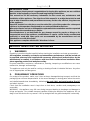
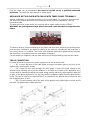
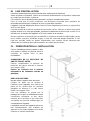
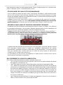
REMOVING PROTECTIVE FILM ETC.
Remove the protection film from the
external and internal walls. (See image)
Remove all information covering from
the inside, and take off all plastic
packaging.
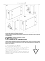
STANDS ADJUSTMENT
Do not use the appliance without feet.
Take the feet from inside, raise the
device on one side and screw them in the
positions shown. They have threaded
inserts (see image).
If they are not used, this prevents airflow
from cooling the electric parts and
outsides of the device which causes
over-heating and damage to
components.
By placing the appliance flat it will ensure
correct functioning. This can be achieved
by fitting the stands correctly and using a
spirit level.

E n g l i s h | 4
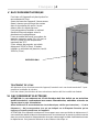
V. WATER CONNECTION
Make sure the device is placed near a water
connection.
Before connecting the device, allow enough
water through to remove any remnants in the
piping so that they did not get into the
magnetic valves.
It is necessary to install a shut-off valve and
mechanical filter between the plumbing and
the device.
The inflowing water shall have a pressure
value comprised between 150 (1,5 bar) and
200 kPa (2bar) and a maximum temperature
of 30°C.
If the inflow pressure value exceeds 200kPa
(2bar), a pressure reducer will have to be
installed, calibrated at 200kPa (2 bar).
WATER INPUT
WATER TREATMENT
In order to ensure trouble-free operation of the device, the
water should have a hardness of maximum 5°f to prevent
lime deposits.
For higher values a water softening station should be installed first.
VI. ELECTRICAL CONNECTION
WARNING: Main connections must be carried out by a qualified and authorised technician
according to national, international and local laws in the country where it is installed.
Before mains connection, ensure that the frequency (…..V) and voltage (….Hz) meet the
requirements indicated in the in the information tag on the back of the appliance.
WARNING: if the device does not come with a trolley to facilitate transport, it is advisable to
connect it first then place it in position in the work area ensuring the cable is not damaged during
placement. This enables easy and safe connection. Ensure that the cable is uniformly exposed
to a room temperature no higher than 50°.
PROOFERS WITH CABLE AND SINGLE PHASE PLUGS
For appliance with cable and plug (single phase 220-240V) the plug merely needs to go into the
appropriate socket (the socket must be adapted for the supplied plug and must withstand the
voltage required by the appliance indicated on the information plate). The product must be
positioned so that the plug is always accessible.
The appliance comes with certified cable and plug therefore they must not be tampered with or
modified.

E n g l i s h | 5
Only the cable can be substituted: this must be carried out by a qualified authorised
technician. The earth wire must always be yellow green.
APPLIANCE NOT SUPPLIED WITH CABLE WITH THREE PHASE TERMINALS
Articles supplied by us come with terminals such as in the image. To connect to the mains see
the label in the manual and stuck to the lower part of the back of the appliance near the
Information plate.
The device must be connected to the electricity with a rubber cable such as H07RN-F.
WARNING: the yellow/green voltage wires in the earth cable must be 3cm onger than the
others.
The device must be connected directly to the mains and must have an easily accessible switch
from the start, installed for the device according to the national, international and local laws in
the country where it is installed. This switch must separate polarization guaranteeing complete
disconnection in accordance with the overvoltage III category.
Correct earthing is obligatory and the earth wire must not be operated by the protection switch.
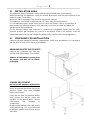
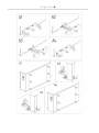
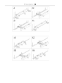
CABLE CONNECTION
Proceed as follows to connect the power supply wire to the terminal board:
•( A1 ) Loosen the tops of the cable gland and open the bottom part of the back of the
appliance by loosening the screws.
•( A2 ) Feed the new cable through the cable gland. Connect the cable voltage to the
terminal strips following the connection diagram on the label on the back of the appliance. Only
connect what is indicated inserting the copper bridge and the electricity cable together under the
screws, in the tightening direction, so the cable and the bridge are tightly fixed by tightening the
screw. The type of cable to be used (HO7RN-F) is indicated on the label for each connection and
the voltage sections in mm².
•( A4 ) Close the bottom part of the back of the appliance by tightening the screws and fit
the cable by tightening the cable gland top.

E n g l i s h | 6

E n g l i s h | 7
Erroneous connection could lead to overheating of the terminal board which could lead to blowout
and electric shock.
Check that all the connections are tight before connecting the device to the mains.
PE = Yellow/Green: “EARTH” protection conductor.
N = Blue: neutral conductor.
L = Brown, Grey, Black: live conductors
Check there is no static discharge between live and earth. Check the limit switch continuity
between the external casing and the earth wire of the mains. It is advised to use a multi tester to
carry out these operations.
CABLE SUBSTITUTION
This must be carried out by a qualified authorised technician. The earth wire must always be
yellow green.
WARNING: the yellow/green voltage wires in the earth cable must be 3cm longer than the
others.
Proceed as follows to connect the power supply wire to the terminal board:
•( A1 ) Loosen the tops of the cable gland and open the bottom part of the back of the
appliance by loosening the screws.
•( A3 ) Loosen the terminal screws and feed the cable conductors through. Take out the old
cable from the cable gland.
•( A2 ) Feed the new cable through the cable gland. Connect the new cable’s conductors to
the terminal following the connection diagram on the label at the lower part of the back of
the appliance. Only connect what is indicated inserting the copper bridge and the electricity
cable together under the screws, in the tightening direction, so the cable and the bridge are
tightly fixed by tightening the screw. The type of cable to be used (HO7RN-F) is indicated on
the label for each connection and the voltage sections in mm².
•( A4 ) Close the bottom part of the back of the appliance by tightening the screws and fit the
cable by tightening the cable gland top.
Check that all the connections are tight before connecting the device to the mains.
WARNING: Erroneous connection could lead to overheating of the terminal board which could
lead to blowout and electric shock.
Check there is no static discharge between live and earth. Check the limit switch continuity
between the external casing and the earth wire of the mains. It is advised to use a multitester to
carry out these operations
The appliance must be connected to the mains using a H07RN-F cable.
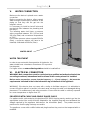
EQUIPOTENTIAL CONNECTION
This connection shall be carried between the different
appliances with the terminal marked by the symbol: (see image).
This terminal enables the connection of Yellow/Green cable with
a section between 2.5 and 10mm² .
The appliance shall be included in an equipotential system
whose efficiency shall be duly verified according to the
provisions of the laws in force.

E n g l i s h | 8
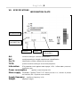
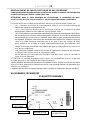
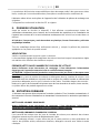
INFORMATIONS
POWER
CONSUMPTION
SUPPLY
WEIGHT
SUPPLY
FREQUENCY
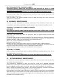
VII. SPECIFICATIONS INFORMATION PLATE
Art.:model according to customer classification
Ref.:model according to internal manufacturer’s classification
Ser. N°: identification number, different for each product
TYPE: product model according to its technical properties
Information: IPX protection level against water sprays / kPa….inflow water pressure /
production year.
Power consumption: appliance nominal power kW
Mains supply: TERMINAL CONNECTION TYPE: device tension in V, number of phases
and neutrals (3N = 3 phases more neutral).
Supply frequency: appliance frequency in Hz.
Weight: appliance weight

E n g l i s h | 9
INSTRUCTIONS FOR THE USER
I. WARNINGS
Read this instructions booklet carefully in that it provides indications regarding safety
and use of the appliance.
Keep carefully for reference at all times.
Incorrect installation, assistence, maintenance, cleaning, tampering or modifications can
cause malfunction, damage and breakage.
The proofer cabinet must only be used for proofing of foods in industrial and professional
kitchens. Any other use is inappropriate. The manufacturer is not liable where it is used
inappropriately.
The appliance is intended for professional use and it shall be used by qualified personnel.
The appliance is not suitable for use by people with low physical or mental abilities or lacking
experience, unless instructed regarding the operation of the device by the personnel in charge
of safety their safety.
Do not leave the appliance unattended in presence of children and ensure that the latter do not
have access to the appliance.
It is thus strongly recommended not to position sources of heat near the appliance.
Do not under any circumstance, leave flammable material near appliance: it can be a fire hazard.
Food container temperatures, accessories or other objects can be very hot; beware of burns
when moving them. Only touch them with relevant thermal protection. Scald danger!
Use fingers to regulate the digital panel options; any other object may damage the device hence
nullify the validity of the warranty.
Damage or breakage of door glass components must be substituted immediately (contact
the Assistence Centre). If it is not in use for long periods of time (many days) it is advisable
to turn it off at the mains. The producer shall not be deemed liable for any damage incurred
by persons or properties, caused by non compliance with the aforementioned instructions
of deriving from tampering with even a single part of the appliance and use of non-genuine
spare parts.This appliance complies with the EU directives in force.
II. TESTING
Make sure all checks required to ascertain strict adherence with the soundness of the systems
and the installation of the appliance with the law regulations as well as technical and safety
instructions provided for by this manual are as well are carried out before operating the
appliance.
There should not be plastic bags inside it, instruction manuals, plastic film or anything
else.
All packaging should have been entirely removed, including the protective film applied on the
walls of the product purchased.
Check every item in the list below:
On reaching the set temperature, the cooking temperature thermostat turns off the heating
elements.

E n g l i s h | 10
FIRST CLEANING OF THE COOKING CHAMBER
Disconnect electrical power from the appliance and wait until the device is cooled
completely before cleaning.
WARNING: the appliance should never be cleaned with high pressure water sprays.
There should never be any residue of solvents or detergents. They should be removed by rinsing
thoroughly using a damp cloth. Appropriate eye, mouth and hand protection should be used.
Possible danger of corrosion.
Clean the walls of the proofer chamber using hot water and soap, then rinse; never use
aggressive or acid products.
III. ORDINARY MAINTENANCE
The user is solely responsible for ordinary maintenance. The Assistence Centre must be
contacted for extraordinary maintenance which requires a specialised authorised technician.
ORDINARY CLEANING OF COOKING CHAMBER
CLEANING
Disconnect electrical power from the appliance and wait until the oven is cooled
completely before cleaning.
At the end of a working day, clean the equipment, both for hygienic reasons and to avoid
malfunctioning.
The proofer must never be cleaned using direct or high pressure water jets. In the same manner,
to clean the appliance do not use pan-scrubbers, steel brushes or scrapers; it is possible to use
stainless steel wool, rubbing it in the direction of the sheets satin finish.
Wait for the cooking compartment to cool down.
Remove the side tray racks.
Manually remove all removable residues place the removable parts inside dishwashers.
To clean the cooking compartment use soapy warm water. Subsequently, all surfaces must be
thoroughly rinsed, being careful to ensure no detergent residues remain.
Only use products recommended by the manufacturer of the appliance.
EXTERNAL CLEANING
Only use a damp cloth with warm water or products suitable for cleaning stainless steel. Do not
use acidic products or ammonia.
WARNING: the appliance should never be cleaned with high pressure water sprays.
IV. EXTRAORDINARY MAINTENANCE
It is advisable to have the appliance subjected to periodical checks (at least once per year) by a
specialised authorised technician.
Any maintenance, installation or repair work must be carried out by qualified authorised
personnel by contacting the Assistance Centre. Before carrying out any operation the appliance
must be plugged out at the mains, turn off the water mains taps and wait for it to cool down.
Before moving the appliance from position, check that the electricity and water connections
(electric cables water pipe and drainage) are correctly plugged out.
If the appliance is on wheels check that electric cables, pipes or anything else are not damaged
while moving it. Ensure the break is on. Avoid placing the device near heat (such as fryers etc.).
After carrying out the task and replacing the appliance in its initial position, check that the electric
and water are connected correctly.

E n g l i s h | 11
V. MAINTENANCE IN CASE OF BREAKAGE
If the appliance breaks, disconnect it from the mains and turn off water.
Before ringing Customer Service, check the chart below).
If the problem persists we advise you to consult a retailer of manufacturer asking for Assistance
Service specifying the problem and supplying your code (Art.) and serial number (Ser N°) This
information is provided on the INFORMATION PLATE on the back of the machine.
SPARE PARTS
Use only authorized parts for product repair. All interventions shall be carried out by authorized
and specialized technical personnel. Contact the Assistance Centre to request spare parts.
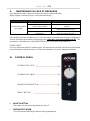
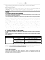
VI. CONTROL PANEL
THERMOSTAT LIGHT
THERMOSTAT KNOB
HUMIDIFICATION BUTTON
ON/OFF BUTTON
•ON/OFF BUTTON
This button turn the leavening cabinet on and off.
•THERMOSTAT KNOB
This knob allows selecting the desired coking temperature.
PROBLEM
CAUSE
SOLUTION
The leavening cabinet
isn’t heating
Supply voltage failure
Restore power supply voltage
Incorrect connection to the
power supply network
Check connection to the power supply
network
Broken resistance
Contact specialised technician for
repair (Assistance Service ).
Broken thermostat of
temperature
Contact specialised technician for
repair (Assistance Service ).

E n g l i s h | 12
•THERMOSTAT LIGHT
When the heating elements are lit they are on because the internal leavening cabinet
temperature is less than the set by the thermostat value dial. When the light goes off it means
that the inside of the leavening cabinet has reached the set temperature.
•STEAM SELECTOR
This button enables humidifying for the length of time it stays pressed.
VII. ADVICE DURING COOKING
Press ON/OFF and turn the temperature dial to the desired value.

Français | 1
25/10/2018
TABLE DES MATIERES: page
INSTRUCTIONS POUR L’INSTALLATEUR
I. AVERTISSEMENTS 2
II. OPERATIONS PRELIMINAIRES 2
III. LIEU D’INSTALLATION 3
IV. PREDISPOSITION A L’INSTALLATION 3
V. RACCORDEMENT ELECTRIQUE 4
VI. DONNEES TECHNIQUES 8
INSTRUCTIONS POUR L’UTILISATEUR
I. AVERTISSEMENTS 9
II. PREMIERE UTILISATION 10
II. ENTRETIEN ORDINAIRE 10
IV. ENTRETIEN EXTRAORDINAIRE 11
V. ENTRETIEN EN CAS DE PANNE 11
VI. PANNEAU E COMMANDES 12
VII. CONSEILS PENDANT L’UTILISATION 12

Français | 2
INTRODUCTION
Cher Client, nous vous remercions et nous vous félicitons d’avoir acheté cet appareil ;
nous espérons que ce sera le début d’une collaboration positive et de longue durée.
Ce livret contient toutes les informations nécessaires pour l’utilisation correcte,
l’entretien et l’installation de cette machine. Le but de ce manuel est de permettre au
technicien installateur et surtout à l’utilisateur direct de prendre toutes les mesures et
les précautions nécessaires pour une utilisation sûre, de longue durée et efficace.
Conserver avec soin ce livret durant tout le cycle de vie de l’appareil, pour des
consultations successives par les opérateurs chargés de l’utilisation et les techniciens
spécialisés. En cas de perte ou détérioration, la documentation de remplacement devra
être demandée directement au producteur ou revendeur.
Le constructeur décline toute responsabilité pour des dommages subis à des personnes
ou des biens par l’utilisation impropre de l’appareil, par des modifications ou réparations
effectuées par du personnel non autorisé et par l’utilisation de composants de rechange
non originaux ou non spécifiques pour le modèle en objet.
Ce dispositif est conforme aux directives CEE en vigueur.
INSTRUCTIONS POUR L’INSTALLATEUR
I. AVERTISSEMENTS
Lire attentivement ce livret avant d’entamer les opérations d’installation et de mise en fonction.
Toutes les opérations d’installation, montage, assistance et entretien extraordinaire
doivent être effectuées par du personnel qualifié et ayant les critères professionnels
nécessaires (autorisé par la société de production ou le revendeur), en respectant les
normes en vigueur dans le pays d’installation et celles concernant la sécurité des
produits et du lieu de travail.
Une installation, assistance, un entretien, nettoyage erronés ou d’éventuelles altérations ou
modifications peuvent être la cause de mauvais fonctionnements, dommages et lésions.
L’appareil doit être utilisé uniquement pour la cuisson ou pour réchauffer des aliments dans le
cadre de cuisines industrielles. Tout autre usage doit être considéré impropre et donc
dangereux.
II. OPERATIONS PRELIMINAIRES
Une fois le produit reçu, s’assurer que ce dernier n’a pas subi de dommages durant le transport
et que l’emballage n’a pas été altéré. En cas de dommages ou de pièces manquantes, informer
immédiatement le transporteur et le revendeur/producteur, en indiquant le code (Art.) et
numéro de série (Ser N°) et en joignant une documentation photographique.
Vérifier que pour atteindre le lieu d’installation il n’y a pas de problèmes d’encombrement qui
empêchent le passage à travers des portes, corridors ou autres passages.
ATTENTION: durant le transport, l’appareil peut risquer de se renverser avec le risque ultérieur
de ruptures et de provoquer des dommages à des biens et des personnes. Utiliser des moyens
adaptés en tenant compte également de son poids. Ne pas traîner et incliner l’appareil pour
aucune raison mais le soulever de terre perpendiculairement et le déplacer horizontalement.

Français | 3
III. LIEU D’INSTALLATION
Il doit être installé dans des pièces fermées bien aérées (pas à l’extérieur).
Avant de placer le dispositif, vérifier les mesures d’encombrement et la position exacte des
raccordements électriques, hydriques.
Faire attention que le positionnement permette l’ouverture complète de la porte.
Faire en sorte que la partie postérieure soit facilement accessible pour permettre les
raccordements électriques, hydriques et pour en permettre l’entretien.
L’appareil n’est pas adapté pour être encastré et il faut obligatoirement laisser un espace libre
de 5 cm tout autour.
Il est déconseillé de le placer à proximité de sources de chaleur, friteuses ou autres sources de
liquides chauds; si ce n’est pas possible, respecter les distances de sécurité qui sont de 50 cm
latéralement, au-dessus de l’appareil et 70 cm à l’arrière de la machine.
Ne pas positionner le dispositif près de materèls ou récipients de matériel inflammable comme
murs, mobiles, mitoyens, bouteilles de gaz ; il peut etre cause de danger d’incendie. Si ceci
n’est pas possible revêtir les parties inflammables avec matériel isolant thermique pas
inflammable en prêtant la plus grande attention aux règles de prévention.
IV. PREDISPOSITION A L’INSTALLATION
Enlever l’emballage externe (caisse en bois
et/ou boîte en carton) et l’éliminer selon la
normative en vigueur dans le pays
d’installation.
ELIMINATION DE LA PELLICULE DE
PROTECTION ET AUTRE
Enlever complètement la pellicule de
protection des parois externes et internes
(voir image à côté)
Enlever de l’intérieur tout le matériel
informatif et les éventuels sachets en
plastique.
REGLAGE DES PIEDS
Ne pas utiliser l’appareil sans les pieds.
Prendre les pieds qui se trouvent à
l’intérieur, lever l’appareil d’un côté et les
placer en les vissant dans les positions
indiquées: en dessous il y a des inserts
filetés (voir image à côté).
Leur non utilisation ne permet pas le
passage de l’air pour le refroidissement des
composants électriques et des parois
externes de la carcasse ce qui cause des
surchauffes qui peuvent endommager les
composants de l’appareil.
La planéité correcte de l’appareil assure un
bon fonctionnement; elle s’obtient en
agissant sur les pieds réglables et se vérifie
à travers un niveau à bulle d’air.

Français | 4
V RACCORDEMENT HYDRIQUE
Font bien sûr l'appareil est placé près d'un
raccordement à l'eau.
Avant de brancher l'appareil, laisser assez
d'eau à travers pour enlever des restes
dans la tuyauterie afin qu'ils n'a pas
obtenu dans les électrovannes.
Il est nécessaire d'installer un robinet
d'arrêt et filtre mécanique entre la
plomberie et le périphérique.
L’eau en entrée doit avoir une valeur de
pression comprise entre 150 (1,5 bar) et
200 kPa (2bar) et une température
maximale de 30°C.
Si les valeurs de pression en entrée
dépassent 200kPa (2bar), il faudra
installer un réducteur de pression, taré à
200kPa (2 bar).
ENTRÉE D'EAU
TRAITEMENT DE L’EAU
Afin d'assurer le bon fonctionnement de l'appareil, l'eau doit avoir une dureté maximale 5° f pour
empêcher les dépôts de calcaire.
Pour des valeurs plus élevées de l'eau adoucisseur station doit être installé tout d'abord.
VI. RACCORDEMENT ELECTRIQUE
ATTENTION: Le raccordement au circuit électrique doit être réalisé par un technicien
qualifié et autorisé, conformément aux normes internationales, nationales et locales en
vigueur dans le pays d’installation.
Avant d’effectuer le raccordement au circuit électrique, vérifier que la tension (…..V) et la
fréquence (….Hz) correspondent à ce qui est indiqué sur la Plaquette Données qui se
trouve sur la partie postérieure de l’appareil.
ATTENTION: si le dispositif est dépourvu d’un support avec roues qui facilite le déplacement, il
est conseillé de réaliser d’abord le raccordement au circuit électrique et ensuite le positionnement
dans son point de travail en faisant attention à ne pas endommager le câble d’alimentation durant
le déplacement. Ceci permet d’effectuer le raccordement électrique en

Français | 5
toute simplicité et dans une plus grande sécurité. Placer le câble de façon à ce qu’aucun des
points ne dépasse de 50°C la température de la pièce.
ÉTUVE EQUIPES DE CABLE ET FICHE MONOPHASE
Pour les appareils équipés de câble et fiche (monophasé 220-240V), il suffit d’insérer la fiche
dans la prise spéciale (la prise doit être adaptée à la fiche fournie et doit supporter la charge
requise par l’appareil indiquée sur la Plaquette Données). Le produit doit être placé de façon à
ce que la fiche soit toujours accessible.
L’appareil est fourni avec câble et fiche certifiés: ils ne doivent pas être manipulés ou changés.
On peut seulement remplacer le câble: cette opération doit être effectuée par un technicien
qualifié et autorisé. Le câble de mise à la terre doit toujours être de couleur jaune vert.
APPAREILS SANS CABLE ET EQUIPES D’UNE BORNE TRIPHASEE
Les articles que nous fournissons sont équipés d’une borne comme sur la figure. Pour effectuer
le raccordement électrique, il faut consulter l’étiquette reportée dans le livret et attachée sur la
partie inférieure de l’arrière de l’appareil à côté de la Plaquette Données.
L’appareil doit être relié au réseau électrique avec un câble en caoutchouc de type H07RN-F.
ATTENTION: dans le câble électrique de raccordement, le conducteur de terre jaune/vert
doit être plus long d’au moins 3 cm par rapport aux autres conducteurs.
L’appareil doit être raccordé de façon directe au circuit électrique et doit être équipé en amont
d’un interrupteur d’accès facile et installé sur l’installation conformément aux normes
internationales, nationales et locales en vigueur dans le pays d’installation. Cet interrupteur doit
avoir une séparation des contacts dans tous les pôles qui puisse garantir la déconnexion
complète sous la catégorie de surtension III.
Un raccordement correct à la terre est obligatoire et le câble de terre ne doit en aucun cas être
interrompu par l’interrupteur de protection.
RACCORDEMENT DU CABLE D’ALIMENTATION
Pour relier le câble d’alimentation au boîtier, procéder comme suit:
• ( A1 ) Dévisser le bouchon de la presse/passe câble et ouvrir la partie inférieure de l’arrière
de l’appareil en dévissant les vis .
• ( A2 ) Faire passer le nouveau câble d’alimentation à travers la presse/passe câble.
• ( A3 ) Relier les conducteurs du nouveau câble d’alimentation à la borne en suivant les
schémas de raccordement qui se trouvent sur l’étiquette située dans la paroi postérieure
de l’arrière de l’appareil. Effectuer uniquement les raccordements indiqués en insérant le
pont en cuivre et le câble électrique ensemble sous la vis, dans le sens de vissage, de
façon qu’en serrant la vis, le câble et le pont soient étroitement fixés. Sur l’étiquette, pour
chaque schéma de raccordement est indiqué quel type de câble utiliser et les sections en
mm² de ses conducteurs.
• ( A4 ) Refermer la partie inférieure de l’arrière de l’appareil en vissant les vis et bloquer le
câble en fixant le bouchon de la presse/passe câble.

Français | 6

Français | 7
Un mauvais raccordement peut causer une surchauffe de la borne, ce qui peut la fondre et
entraîner des risques de décharges électriques.
Vérifier que tous les raccordements électriques sont bien serrés avant de raccorder le étuve au
circuit électrique.
PE = Jaune/Vert : conducteur de protection “TERRE”.
N = Bleu : conducteur de neutre
L1, L2, L3 = Marron, Gris, Noir : conducteurs de phase
Vérifier l’absence de dispersion électrique entre phases et terre. Vérifier la continuité électrique
entre la carcasse externe et le fil de terre du circuit. Il est conseillé d’utiliser un multimètre pour
effectuer ces opérations.
RACCORDEMENT EQUIPOTENTIEL
Ce raccordement doit être effectué entre appareils différents
avec la borne indiquée par le symbole: (voir image à côté).
Cette borne permet de relier un câble de couleur Jaune/vert avec
section comprise entre 2.5 et 10mm².
L’appareil doit être inclus dans un système équipotentiel dont
l’efficacité doit être bien vérifiée selon ce qui est reporté dans la
normative en vigueur.
La page est en cours de chargement...
La page est en cours de chargement...
La page est en cours de chargement...
La page est en cours de chargement...
La page est en cours de chargement...
-
 1
1
-
 2
2
-
 3
3
-
 4
4
-
 5
5
-
 6
6
-
 7
7
-
 8
8
-
 9
9
-
 10
10
-
 11
11
-
 12
12
-
 13
13
-
 14
14
-
 15
15
-
 16
16
-
 17
17
-
 18
18
-
 19
19
-
 20
20
-
 21
21
-
 22
22
-
 23
23
-
 24
24
-
 25
25


Axis AX-PR5 Le manuel du propriétaire
- Taper
- Le manuel du propriétaire
- Ce manuel convient également à
dans d''autres langues
- English: Axis AX-PR5 Owner's manual
Autres documents
-
Sammic SV-21 Manuel utilisateur
-
Sammic SL-19D Manuel utilisateur
-
Bartscher 109558 Mode d'emploi
-
-
-
Hendi 225516 Manuel utilisateur
-
-
Blizzard STORM100BTDP Le manuel du propriétaire
-
Zodiac Edenpac 5D Instructions For Installation And Use Manual
-
STARBUCKS E2S Manuel utilisateur