Kichler Lighting 5368CH Manuel utilisateur
- Taper
- Manuel utilisateur
La page est en cours de chargement...
La page est en cours de chargement...

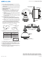
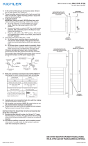
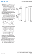
1) At the center of the back pan are knockout slots. Remove
the set that matches your outlet box.
2) Locate indentation along edge of back pan. Position back pan
on wall over outlet box so indention is located at the bottom
of the back pan.
3) Thread mounting screw into each slot in back pan and into
holes in outlet box. Tighten mounting screws to secure the
back pan to the outlet box.
4) TURN OFF POWER.
IMPORTANT: Before you start, NEVER attempt any work
without shutting off the electricity until the work is done.
a) Go to the main fuse, or circuit breaker, box in your
home. Place the main power switch in the “OFF”
position.
b) Unscrew the fuse(s), or switch “OFF” the circuit breaker
switch(s), that control the power to the fixture or room
that you are working on.
c) Place the wall switch in the “OFF” position. If the fixture
to be replaced has a switch or pull chain, place those in
the “OFF” position.
5) Connect fixture ground wire to outlet box ground wire with
wire connector. Never connect ground wire to black or white
ower supply wire.
6) Make wire connections (connectors not provided). Reference
chart below for correct connections and wire accordingly.
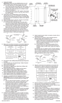
7) Carefully push wire connections back into outlet box making
sure all connections remain secure.
8) Slip faceplate of fixture over back pan. NOTE: Be certain
wires do not get pinched between back pan and faceplate.
9) Align holes in top and bottom of faceplate with each hole in
top and bottom of back pan.
10) Raise glass up to fixture. Pass hole in glass over socket.
11) Thread socket ring onto socket. Tighten socket ring to secure
glass in place. (DO NOT over tighten.)
1) Au centre du panneau arrière se trouvent des fentes amovibles.
Enlever l’ensemble correspondant à votre boîte à prises.
2) Localiser l’indentation le long du bord du panneau arrière.
Positionner le panneau arrière sur le mur au-dessus de la
boîte de sortie de manière à ce que l’indentation soit située
au fond du panneau arrière.
3) Serrer la vis de fixation dans chaque fente du panneau
arrière et dans les trous de la boîte à prises. Serrer les vis de
fixation pour fixer le panneau arrière de la boîte à prises.
4) COUPER LE COURANT.
IMPORTANT: TOUJOURS couper l’électricité avant de
commencer le travail.
a) Localiser le coffret à fusibles ou le disjoncteur du
domicile. Mettre l’interrupteur principal en position
d’Arrêt.
b) Dévisser le ou les fusibles (ou mettre le disjoncteur sur
Arrêt) qui contrôlent l’alimentation vers le luminaire ou la
pièce dans laquelle le travail est effectué.
c) Mettre l’interrupteur mural en position d’Arrêt. Si le luminaire
à remplacer est doté d’un interrupteur ou d’une chaîne
connectée à l‘interrupteur, placer ces éléments en
position d’Arrêt.
5) Avec l’attache-fil, connecter le fil de mise á la terre au fil
d’alimentation noir ou á celui qui est blanc.
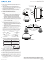
Connect Black or
Red Supply Wire to:
Connect
White Supply Wire to:
Black White
*Parallel cord (round & smooth) *Parallel cord (square & ridged)
Clear, Brown, Gold or Black
without tracer
Clear, Brown, Gold or Black
with tracer
Insulated wire (other than green)
with copper conductor
Insulated wire (other than green)
with silver conductor
*Note: When parallel wires (SPT I & SPT II)
are used. The neutral wire is square shaped
or ridged and the other wire will be round in
shape or smooth (see illus.)
Neutral Wire
Date Issued: 3/7/14 IS-5368-CB
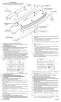
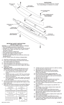
FACEPLATE
PLAQUE FRONTALE
INSTRUCTIONS
For Assembling and Installing Fixtures in Canada
Pour L’assemblage et L’installation Au Canada
BACKPAN
PANNEAU ARRIÈRE
SOCKET RING
ANNEAU DE LA DOUILLE
GLASS
VERRE
We’re here to help 866-558-5706
Hrs: M-F 9am to 5pm EST
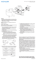
6) Connecter les fils (connecteurs non fournis). Se reporter au
tableau ci-dessous pour faire les connexions.
7) Replacer soigneusement les fils dans la boîte à prises en
veillant à ce que les connexions ne soient pas déconnectées.
8) Déplacer la plaque frontale du luminaire par-dessus le
panneau arrière. Remarque: Veiller à ce que les fils ne se
retrouvent pas coincés entre le panneau arrière et la plaque
frontale.
9) Aligner les trous situés en haut et en bas de la plaque
frontale aux trous en haut et en bas du panneau arrière.
10) Soulever le verre jusqu’au luminaire. Passer le trou dans le
verre sur la douille.
11) Serrer l’anneau de la douille sur la douille. Serrez la bague
de la douille pour fixer le verre en place. (NE PAS serre
avec excès).
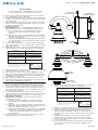
Connect Black or
Red Supply Wire to:
Connect
White Supply Wire to:
Black White
*Parallel cord (round & smooth) *Parallel cord (square & ridged)
Clear, Brown, Gold or Black
without tracer
Clear, Brown, Gold or Black
with tracer
Insulated wire (other than green)
with copper conductor
Insulated wire (other than green)
with silver conductor
*Note: When parallel wires (SPT I & SPT II)
are used. The neutral wire is square shaped
or ridged and the other wire will be round in
shape or smooth (see illus.)
Neutral Wire
SCREW
VIS
INDENTATION
INDENTATION
-
 1
1
-
 2
2
-
 3
3


Kichler Lighting 5368CH Manuel utilisateur
- Taper
- Manuel utilisateur
dans d''autres langues
- English: Kichler Lighting 5368CH User manual
- español: Kichler Lighting 5368CH Manual de usuario
Documents connexes
-
 Kichler Lighting 49117AZLED Manuel utilisateur
-
Kichler 45423OZ Manuel utilisateur
-
-
Kichler 623CH Manuel utilisateur
-
 Kichler Lighting 6048AZ Manuel utilisateur
-
 Kichler Lighting 6040NI Manuel utilisateur
-
 Kichler Lighting 10630PNLED Manuel utilisateur
-
-
 Kichler Lighting 42091PNLED Manuel utilisateur
-
 Kichler Lighting 45087PNLED Manuel utilisateur


