Audio Technica AT-LP1240-USB XP EDITION Manuel utilisateur
- Catégorie
- Platines audio
- Taper
- Manuel utilisateur
Ce manuel convient également à

AT-LP1240-USB
XP EDITION
User Manual
Direct Drive Professional Turntable
Manuel de l’utilisateur
Platine professionnelle à entraînement direct
Manual de usuario
Tocadiscos profesional con accionamiento directo

1
Introduction
Thank you for purchasing this Audio-Technica product.
Before using the product, read through this user manual to ensure that you will use the product correctly. Please keep this manual for future reference.
This product can be used only in the countries where the product is sold. Make sure that the operating voltage of the product is correct for the
country you live in.
Package contents
Make sure that you have all the included items listed below before using this product.
If some items are missing or damaged, contact your local Audio-Technica dealer.
• Turntable body
• Dust cover
• Platter
• Slip mat
• Counterweight
• Headshell (AT-HS1) with cartridge (AT-XP5)
• 45 RPM adapter
• USB cable (1.9 m (6.2'))
• RCA audio cable (Approx. 1.4 m (4.6'))
• Power cable
• Stylus target light
• User manual (this document)
After purchase, we suggest that you save all packaging materials for possible future storage, moving, or shipping.

2
Safety precautions
Although this product was designed to be used safely, failing to use
it correctly may result in an accident. To ensure safety, observe all
warnings and cautions while using the product.
Cautions for the product
Warning:
• Do not use a power cable other than the included one. Doing so may
cause a fire, electric shock, damage or malfunction.
• Stop using the product and disconnect the power cable from the
product if the product begins to malfunction, producing smoke, odor,
heat, unwanted noise or showing other signs of damage. In such a
case, contact your local Audio-Technica dealer. Continuing to use the
product may cause fire or damage.
• Do not place any naked flame sources (such as lighted candles) on
the product.
• Do not disassemble, modify or attempt to repair the product to
prevent electric shock, malfunction or fire.
• Do not subject the product to strong impact to prevent electric shock,
malfunction or fire.
• Do not handle the product with wet hands to prevent electric shock
or injury.
• Do not expose the product to drips or splashes to prevent electric
shock, malfunction or fire.
• Do not put foreign matter such as combustible materials, metal, or
liquid in the product to prevent electric shock, malfunction or fire.
• Do not cover the product with a carpet or a cloth to prevent fire or
injury by overheating.
• Store the included plastic bag out of the reach of small children or
away from a heat sources to prevent accident or fire.
• Place the product close enough to the AC outlet to easily grasp the
power cable plug at any time. In case of emergency, disconnect the
power cable plug of the product quickly.
• Connect the product with Class
Ⅰ
construction to the AC outlet with
a protective grounding connection.
Caution:
• Do not install the product on an unstable surface to prevent injury or
damage from the product falling.
• Do not install the product in a poorly ventilated place to prevent
accident or fire by accumulated heat. Make enough clearance around
the product to radiate heat when installing it on a rack.
• Do not store the product in direct sunlight, near heating devices, or
in hot, humid, or dusty places to prevent electric shock, malfunction
or fire.
• Do not place any objects filled with liquids, such as vases, on the
product to prevent electric shock, malfunction or, in the worst case,
fire in the worst case.
• Do not use chemicals such as benzine, thinner or electrical contact
cleaner to prevent damage or malfunction.
For customers in the USA
UL/CSA notice
Safety instructions
1. Read these instructions.
2. Keep these instructions.
3. Heed all warnings.
4. Follow all instructions.
5. Do not use this apparatus near water.
6. Clean only with dry cloth.
7. Do not block any ventilation openings. Install in accordance with the
manufacturer’s instructions.
8. Do not install near any heat sources such as radiators, heat
registers, stoves, or other apparatus (including amplifiers) that
produce heat.
9. Do not defeat the safety purpose of the polarized or grounding-type
plug. A polarized plug has two blades with one wider than the other.
A grounding type plug has two blades and a third grounding prong.
The wide blade or the third prong are provided for your safety. If the
provided plug does not fit into your outlet, consult an electrician for
replacement of the obsolete outlet.
10. Protect the power cord from being walked on or pinched particularly
at plugs, convenience receptacles, and the point where they exit
from the apparatus.
11. Only use attachments/accessories specified by the manufacturer.
12. Use only with the cart, stand, tripod, bracket or table specified by
the manufacturer, or sold with the apparatus. When a cart is used,
use caution when moving the cart/apparatus combination to avoid
injury from tip-over.
13. Unplug this apparatus during lightning storms or when unused for
long periods of time.
14. Refer all servicing to qualified service personnel. Servicing is
required when the apparatus has been damaged in any way, such
as power-supply cord or plug is damaged, liquid has been spilled
or objects have fallen into the apparatus, the apparatus has been
exposed to rain or moisture, does not operate normally, or has been
dropped.
Caution:
To prevent electric shock, do not remove the cover. There are
no user-serviceable parts inside. Internal adjustments are for qualified
professionals only. Refer all servicing to qualified service personnel.
Caution: To prevent electric shock, do not use this polarized plug
with an extension cord, receptacle or other outlet unless the blades
can be fully inserted to prevent blade exposure.
The lightning Flash Symbol, with “The Lightning Flash with
arrowhead symbol within an equilateral triangle, is intended
to alert the user to the presence of uninsulated “dangerous
voltage” within the product enclosure that may be of sufficient
magnitude to constitute a risk of shock to persons”.
The exclamation Point Symbol, with “The exclamation
point within an equilateral triangle is intended to alert
the user to the presence of important operating and
maintenance (servicing) instructions in the literature
accompanying the product”.
CAUTION
RISK OF ELECTRIC SHOCK
DO NOT OPEN

3
Safety precautions
FCC Notice
Warning:
This device complies with Part 15 of the FCC Rules. Operation is
subject to the following two conditions: (1) This device may not cause
harmful interference, and (2) this device must accept any interference
received, including interference that may cause undesired operation.
Caution:
You are cautioned that any changes or modifications not expressly
approved in this manual could void your authority to operate this
equipment.
Note: This equipment has been tested and found to comply with
the limits for a Class B digital device, pursuant to part 15 of the FCC
Rules. These limits are designed to provide reasonable protection
against harmful interference in a residential installation. This equipment
generates, uses and can radiate radio frequency energy and, if not
installed and used in accordance with the instructions, may cause
harmful interference to radio communications. However, there is no
guarantee that interference will not occur in a particular installation. If
this equipment does cause harmful interference to radio or television
reception, which can be determined by turning the equipment off and
on, the user is encouraged to try to correct the interference by one or
more of the following measures:
– Reorient or relocate the receiving antenna.
– Increase the separation between the equipment and receiver.
– Connect the equipment into an outlet on a circuit different from that
to which the receiver is connected.
– Consult the dealer or an experienced radio/TV technician for help.
For customers in Canada
IC statement:
CAN ICES-3 (B)/NMB-3(B)
Notes on use
Turntable body
• Do not set and use the product in locations that are considerably hot
or humid, dirty, or subject to extreme vibrations.
• The product should be positioned on a flat, level surface.
Cartridge
• Attach the protector to protect the stylus when the product is not in
use.
• Do not touch the stylus of the cartridge with your finger.
• Do not allow the cartridge's stylus to bump against the platter or the
edge of the record.

4
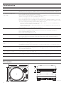
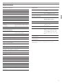
Part names and functions
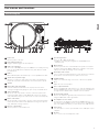
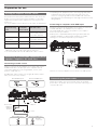
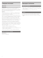
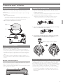
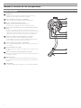
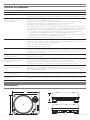
Overall diagram
11
Speed range button
Select +/- 10 or 20% speed range.
• +/-50% is selected by pressing both the 10 and 20 buttons
simultaneously.
12
Quartz button
Turns the pitch function on and off. When the quartz is activated
the platter will hold the RPMs at 0% pitch, regardless of the pitch
slider position and speed range control settings.
13
Pitch adjust slide control
Use in conjunction with pitch button to vary the platter’s rotational
speed. In the center detent position quartz lock is active.
14
45-RPM adapter
Adapt 7" records with large center holes to fixed center spindle
15
Feet
Adjust the level of the product.
16
Stereo output terminals
Connect the RCA audio cable. Connect it to either the amplifier's (DJ
mixer's) PHONO input jack or its line input jack. The red terminal is
the right channel and the white terminal is the left channel.
17
Ground (earth) terminal
Connect the amplifier's ground (earth) terminal to this terminal
using the RCA audio cable's ground line.
18
Pre-amplifier selector switch
If connecting to an amplifier's (DJ mixer's) PHONO input jack, set
this switch to the PHONO position. If connecting to the LINE/AUX
jack of an amplifier (DJ mixer), set this switch to the LINE position.
19
USB output
Use this output to connect your turntable to the USB input of your
computer.
20
AC inlet
Use to connect the included power cable.
1
Power dial
Controls power to the unit.
2
Dual start/stop buttons
Engages and disengages the motor/platter.
3
Platter speed buttons
Select 33 or 45 RPM platter speed. 78 RPM is selected by pressing
both the 33 and 45 buttons simultaneously; both buttons should
be illuminated.
4
Platter
Cast aluminum platter mounts directly to center spindle/motor shaft.
5
Strobe dots (on platter edge)
Operate in conjunction with stroboscopic light located under the
power dial to provide visual indication of accurate platter speeds.
6
Spindle
7
Removable stylus target light
Provides illumination directed at the stylus position for easier
cueing in low light. Easily plugs into jack on top of turntable deck.
8
Start control knob
Rotate the start control knob to increase or decrease platter start
time between 0.2 – 6.0 seconds. (Minimum setting is the quickest
start; maximum setting is the slowest start to reach selected speed.)
9
Brake control knob
Rotate the brake control knob to increase or decrease platter brake
time between 0.2 – 6.0 seconds. (Minimum setting is the quickest
stop; maximum setting is slowest.)
10
Reverse control button
Controls platter’s rotational direction.
1
2
2
12
13
14
5
7 8 9
4 6
10
3
18 2015 1517 191611

5
Part names and functions
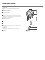
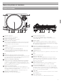
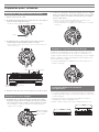
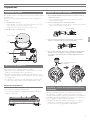
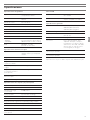
Tonearm
21
Counterweight
Balances the tonearm and provides adjustment for proper
downward tracking force on the stylus.
22
Tracking force gauge ring
Use to adjust the tracking force.
23
Tonearm height lock
Locks the tonearm height setting.
• Always fully unlock before attempting to make a height adjustment.
24
Anti-skate control dial
While the record is playing, a force acts on the stylus tip to pull it
inward. This force can be counteracted by setting the same values
for anti-skate and the tracking force.
25
Tonearm lift control lever
Controls action of tonearm lift.
• Lift mechanism is hydraulically damped to slow tonearm descent.
26
Tonearm rest with clamp
Use the clamp to secure the tonearm so that it does not move.
27
Tonearm lift
Moves the tonearm vertically to and from the face of the record.
28
Tonearm height adjustment dial
Raises and lowers the tonearm to allow it to remain parallel to the
record surface.
29
Locking ring
Rotate the ring to the left (counterclockwise) to secure the
headshell. To remove the headshell, rotate the ring to the right.
30
Headshell
The cartridge (AT-XP5) is attached to the headshell (AT-HS1).
29
30
21
25
26
27
28
24
23
22

6
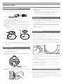
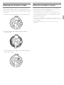
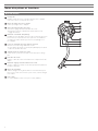
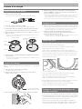
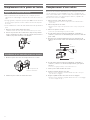
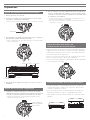
Preparation for use
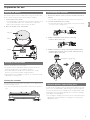
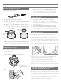
Placing the platter
This product requires some assembly before using it for the first time.
Do not connect the power cable until assembly is complete.
1. Set the platter on the spindle.
• To avoid damaging the spindle when seating the platter, align the positions
of the spindle and the platter's hole, and then slowly seat the platter.
• Make certain that the platter is fully seated on the spindle.
2. Place the slip mat on top of the platter.
Setting up the turntable
• Position the product on a level surface.
• To avoid the effects of vibrations and acoustic pressure, do not
mount the product next to such items as speakers.
• The product may pick up radio static if placed next to a radio.
Therefore, try to keep the product away from radios.
• If the product is near equipment (cell phone, etc.) that emits strong
radio waves, noise may occur.
Leveling the turntable
After positioning the product where you want to use it, adjust the feet
so that the product is level.
• Use a level (sold separately) as needed to ensure that the product is
level.
Assembling the tonearm
1. Remove the cable tie used to secure the tonearm at the time of
delivery.
• Use the clamp to temporarily secure the tonearm to the tonearm rest.
2. Insert the headshell into the tonearm.
• Hold the right and left edges of the headshell so that you do not damage
the stylus or cut the cartridge’s wires.
3. With the headshell inserted, turn the locking ring
counterclockwise (to the left).
4. With the tracking force gauge ring facing forward, attach the
counterweight to the back of the tonearm, and slowly turn it
counterclockwise (to the left).
Tonearm balance and tracking force
In order for the cartridge to pick up sound correctly from the record’s
grooves, the tonearm’s balance and tracking force must be adjusted
to fit the specifications of the cartridge. If the tonearm’s balance and
tracking force are not properly adjusted, the record or the cartridge’s
stylus may become damaged.
• Do not drag the cartridge’s stylus across the record or platter when
adjusting the tonearm’s balance or tracking force. Doing so may
damage the stylus.
Spindle
Platter
Slip mat
Locking ring
Tracking force gauge ring

7
Preparation for use
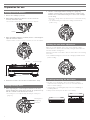
Setting tonearm balance
1. Remove the cartridge's protector.
2. While lightly holding the headshell so as not to move the
tonearm, unlatch the clamp.
• The tonearm is tilted because the balance has yet to be adjusted.
3. While still lightly holding the headshell, turn the counterweight to
adjust the tonearm’s balance.
•
Adjust the balance so that the tonearm is level when you release the headshell.
4. Return the tonearm to the tonearm rest and latch the clamp.
Setting tracking force
1. While supporting the counterweight so that it does not move,
turn the tracking force gauge ring so that its “0” position lines up
with the centerline on the back of the tonearm.
• The tracking force is not adjusted simply by turning the tracking force
gauge ring.
2. Turn the counterweight and the tracking force gauge ring
together counterclockwise (to the left) until the centerline value
matches the recommended tracking force value for the cartridge
you are using.
• Refer to the cartridge maker’s specifications for the recommended tracking
force value.
• The standard tracking force value for the cartridge provided with this
product is 3.0 g.
Setting the anti-skate adjustment
While the record is playing, a force acts on the stylus tip to pull it
inward. This force can be counteracted by setting the same values for
anti-skate and the tracking force.
Adjust the anti-skate control dial to have the same value as the tracking
force value.
• The standard tracking force value for the cartridge provided with this
product is 3.0 g.
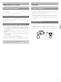
Installing/removing the dust cover
• The dust cover is designed to protect the product's sensitive
components when the product is not in use. It should remain off
while records are playing.
• Using the dust cover during play may result in record damage or
sound degradation.
• Always remove and replace the dust cover carefully.
Tonearm Counterweight
Adjust so that tonearm is level
Clamp
Centerline
Tracking force
gauge ring

8
Preparation for use
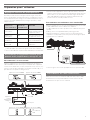
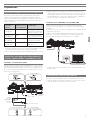
Setting pre-amplifier selector switch
This product has a built-in phono equalizer function. You can use the
product, even if you do not have a phono amplifier or connectable
equipment with a built-in phono amplifier, by connecting an active
speaker, etc.
Use the pre-amplifier selector switch to set the output, as shown below.
Connectable
equipment being
used
Position of
pre-amplifier
selector switch
Where to connect the
RCA audio cable
Device with phono
input
PHONO Phono input jack and
ground (earth) terminal of
connectable equipment
Device without
phono input
LINE AUX or line input jack of
connectable equipment
PC sound card LINE Sound card's line input jack*
1
Device with USB
input
LINE USB input of your
computer*
2
*
1
An audio adapter (sold separately) may be required to connect the
RCA audio cable to the PC sound card's line input jack.
*
2
Use included USB cable instead of RCA audio cable to connect.
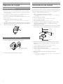
Connecting to connectable equipment (active
speakers, amplifiers, DJ mixer, etc.)
Connecting to audio source
Align the settings for the pre-amplifier selector switch and connect
the RCA audio cable to an input jack that is compatible with the
connectable equipment you are using (amplifier, receiver, active
speakers, sound card, etc.).
The RCA audio cable's red jack is for the right (R) channel, and the
white jack is for the left (L) channel.
• Depending on the equipment you are connecting, a ground (earth)
terminal may exist near the phono input jack. If this is the case,
connect to it using the ground line from the RCA audio cable. This
will help prevent a low humming noise that might otherwise be heard
during playback.
Connecting to computers with USB input
Follow the settings for the pre-amplifier selector switch to connect the
included USB cable to the USB input of your computer.
The included USB cable connects the product to your computer
without need for special drivers.
Audacity (refer to http://www.audacityteam.org for details) and other
compatible third-party recording software packages are available,
allowing you to record from the product to your computer.
• Be sure to set the pre-amplifier selector switch to the LINE position.
Connecting the power cable
Finally, after all audio connections are made, attach the included
power cable to the product. Then connect the power cable’s plug to a
convenient AC outlet.
With PHONO input*
With PHONO input*
Without PHONO input
Without PHONO input
Or LINE
connection
To outlet
To
USB port
To outlet
Connectable
equipment
(amplifier,
DJ mixer,
etc.)

9
Playing a record
Before playing a record
1. Remove the cartridge's protector.
• If the tonearm is fixed to the tonearm rest, unlatch the clamp.
2. Turn the power dial to the ON position.
• The speed selector and strobe illuminator will light up.
3. If desired, plug in the stylus target light for illumination of the
stylus tip position on the record.
4. Place the record on the platter so that the center hole aligns with
the spindle.
• If playing a 45 RPM record, attach the 45 RPM adapter (see the diagram to
the right below).
5. Set the platter rotation speed (33/45/78) to match that of the record.
• To set the platter speed for 78 RPM, press both the 33 and 45 RPM buttons
simultaneously.
Playing a record
Lower the volume of the amplifier, speakers, etc. sufficiently.
1. Press one of the start/stop button.
• The platter begins to rotate.
2. Raise the tonearm by lifting the tonearm lift control lever to the
UP position.
3. Position the tonearm over the desired location (groove) on the
record.
4. Lower the tonearm by moving the tonearm lift control lever to the
DOWN position. The tonearm descends slowly onto the record
and play begins.
• Alternatively, you can skip steps 2 to 4, and use your fingers to lift the
headshell, move the tonearm over the desired location on the record, and
then place the headshell down to begin playing the record.
• Do not subject the product to strong impact during playback.
Setting pitch
1. Press the quartz button to turn the pitch function off.
• The internal quartz lock holds the platter at the precise rated speed (0 %
pitch), regardless of the pitch slider position and speed range control settings
when the quartz button is on.
2. Use the pitch adjust slide control in conjunction with the pitch
buttons to vary the platter’s rotational speed by as much as +/-
50%.
• When the pitch adjust slide control is in the center detent position, the
quartz lock is active.
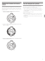
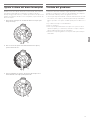
Measuring pitch
Four rows of strobe dots on the platter edge are designed to measure
and verify the platter speed (pitch).
Confirm the moves of strobe dots illuminated by the stroboscopic light
located under the power dial.
When the corresponding row of strobe dots appears to be stationary,
the turntable will be at the operating speed percentage indicated below.
If the dots appear to be moving to the right, the platter is moving
below rated speed. If they appear to be moving to the left, the platter is
moving above rated speed.
+7.2 % change in pitch when the dots in the top row are stationary [point
to top row of dots]
+3.3 % change in pitch when the dots in the second row are stationary
[point to second row of dots]
0 % change in pitch (normal speed) when the dots in the third row are
stationary [point to third row of dots]
-3.3 % change in pitch when the dots in the bottom row are stationary
[point to bottom row of dots]
Adjusting platter start speed and brake speed
Rotate the start control knob to increase or decrease platter start time
between 0.2 – 6.0 seconds. (Minimum setting is the quickest start;
maximum setting is the slowest start to reach selected speed.)
Rotate the brake control knob to increase or decrease platter brake
time between 0.2 – 6.0 seconds. (Minimum setting is the quickest stop;
maximum setting is slowest.)
45-RPM
adapter
At 33-1/3 RPM At 45 RPM
Record
Slip mat
Platter
Tonearm lift
control lever
Protector

10
Playing a record
Reversing the record
If desired, press the reverse control button to reverse the rotation of the
platter.
• The reverse control button will illuminate.
Pausing the record
After lowering the volume of the amplifier, speakers, etc. sufficiently, lift
the tonearm with the tonearm lift control lever.
Stopping the record
1. Lower the volume of the amplifier, speakers, etc. sufficiently.
2. Lift the tonearm lift control lever, return the tonearm to the
tonearm rest, and fix it with the clamp.
3. If using the stylus target light, turn it off by removing it from the
jack.
4. Press one of the start/stop buttons to stop the platter rotation.
• The platter slows down and rotation stops.
5. Turn the power dial to the OFF position.
6. Remove the record after the platter has come to a complete stop.
• To prevent the record from becoming scratched or warped, remove it
after use.
• Do not use a platter other than the one provided.
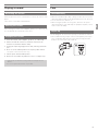
Care
Turntable body
• When the turntable body is dirty or dusty, first disconnect the power
cable plug, and then wipe off the dirt and dust with a soft, dry cloth.
• Do not use benzenes, thinners, etc.
• When storing the product for a long time, disconnect the power
cable plug from the outlet and wrap the equipment in plastic; do not
allow it to become damp.
Stylus tip
• If dirt and grime are stuck to the stylus tip, clean it before each use.
• We recommend using a stylus cleaner (sold separately) if the stylus
tip is considerably dirty. Clean the stylus tip by moving the brush
from the rear to the front of the stylus tip.

11
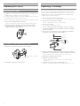
Replacing the stylus
Removing the stylus
• In addition to the deterioration of sound quality, records may also be
damaged as the cartridge’s stylus tip wears down.
• As a rule of thumb, replace the stylus after 300 hours of use. Heavy
scratching may shorten the life of the stylus.
• Be sure to disconnect the product’s power cable plug from the outlet.
1. Release the headshell from the tonearm.
• Fix the tonearm with the clamp and then remove the headshell gently.
2. After removing the cartridge's protector, remove the stylus
by pulling in the direction of the arrow without touching the
cantilever, stylus tip, and magnets.
Installing a new replacement stylus
1. Mount the new replacement stylus to the cartridge.
2. Mount the headshell onto the tonearm.
Replacing a cartridge
Refer to the user manual for the cartridge that you will be using if you
are replacing the cartridge (AT-XP5) included with this product with
another, commercially available cartridge. After you replace the old
cartridge with a new one, you must readjust the overhang and the
tonearm’s balance and tracking force.
1. Release the headshell from the tonearm.
• Use the clamp to secure the tonearm and then remove the headshell gently.
2. Remove the stylus from the cartridge.
• Refer to “Removing the stylus” on p. 11 (this page).
3. Remove the lead tips.
• Be careful not to damage the lead tips.
4. Using a commercially sold, non-magnetic slotted screwdriver,
remove the installation screws, and then remove the cartridge
from the headshell.
5. Refer to the user manual for the new cartridge for mounting
instructions and connecting to the lead tips.
6. Using a commercially sold, non-magnetic slotted screwdriver,
tighten the screws in both places, and then adjust the overhang.
• After the adjustments are complete, tighten the screws securely.
7. Attach the headshell to the tonearm.
8. Adjust the tonearm's height.
• Refer to “Adjusting the tonearm's height” on p. 12 while doing the
adjustments.
9. Adjust the tonearm balance and tracking force.
• Refer to "Setting tonearm balance" and "Setting tracking force" on p. 7.
Pull
Align the position of the inner
protrusion.
Washers
Screws
Nuts

12
Adjusting the tonearm's height
When installing a cartridge other than the one provided, you must
maintain a suitable distance between the cartridge and the surface of
the record. Place the stylus on the record and confirm that the tonearm
is parallel to the record's surface. If it is not parallel, adjust the height
of the tonearm.
1. Rotate the tonearm height lock to loosen the tonearm's anchor.
2. Rotate the tonearm height adjustment dial and adjust the
tonearm's height.
3. After the adjustments are complete, rotate the tonearm height
lock to set the tonearm.
When the turntable is moved
Using the product's original packing materials, wrap the turntable in
the reverse order from when you unwrapped it. If you do not have the
packaging materials, take the following measures:
• After unplugging the power cable plug from the outlet, remove the
platter, and then wrap it so that it does not get damaged. If the product
is moved while the platter is still seated, it may damage the spindle.
• Fix the tonearm with the clamp.
• Remove the counterweight.
• Remove the headshell from the tonearm with the cartridge's protector
attached, and then wrap the entire headshell assembly so that it does
not get damaged.
• Wrap the turntable body with a soft cloth so that it does not get
damaged.

13
Troubleshooting
Problem Solution
The platter does not spin. • Is the power cable connected to the outlet? Connect power cable to the outlet.
• Has the power cable's plug come off? Check whether or not the plug is properly attached to the product.
The platter spins, but there is
no sound or the volume is not
loud enough.
• Is the cartridge's protector still in place? Remove the cartridge's protector.
• Is the tonearm in the lift position? Lower the tonearm.
• Are the function settings and input for connected equipment (amplifier, etc.) selected correctly? Check
whether the settings for the connected equipment are correct.
• Is the stylus damaged? Check the stylus and replace it, if necessary.
• Is the stylus placed correctly on the body of the cartridge? Check the cartridge and adjust it, if necessary.
• Are the setting positions for the pre-amplifier selector switch correct? Check that the pre-amplifier settings
are correct, noting the following common problems and their causes:
- If there is no sound, or if the volume is not loud enough, the product is set to the “PHONO” position
and connected to the amplifier’s AUX/LINE input.
- If the volume is too loud or is distorted, the product is set to the “LINE” position and connected to the
amplifier's PHONO input.
• Is the tracking force set too heavy? Adjust the tracking force.
The stylus skips. • Is the tracking force set too light or too heavy? Adjust the tracking force.
• Is the anti-skate set improperly? Verify anti-skate is set for same value as cartridge tracking force.
• Is the record warped? Check the record.
• Is the record scratched? Check the record.
There is howling. • Is the product picking up excessive vibrations from the floor, surfaces of the walls, or nearby speakers?
Decrease the vibrations or mount the product on a surface that is not subject to the effects of vibrations.
• Is the product mounted on an unstable surface? Check whether the surface on which the product is
mounted is suitable.
There is noise when the record
is playing.
• Is there dust on the cartridge’s stylus tip? If dust is stuck to the stylus tip, clean it with a commercially
sold brush.
The sound when the record is
playing is either too fast or too
slow.
• Are the speed settings for the product correct? Use the platter speed buttons to select the correct speed
for the type of record being played.
• Is variable pitch engaged? Depress quartz button or return pitch adjust slider to center detent position to
engage quartz lock.
Moving pitch adjust slider
produces no effect.
• If the LED next to the pitch adjust slider center detent position remains blue when the slider is moved,
quartz lock is engaged. Depress the quartz button to disengage the quartz lock and activate variable
pitch. The LED should turn off.
Strobe dots are difficult to see and/
or stylus illuminator is very dim.
• Excessively bright or fluorescent light interferes with strobe indicator. Hold hand, record jacket, etc. over
strobe indicator to shield it from bright light.
Humming is heard during
playback.
• Is the ground line connected correctly? Make sure the ground line is properly connected.
• Is the headshell attached to the tonearm firmly? Make sure the locking ring is tight.
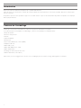
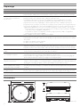
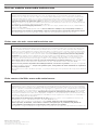
Dimensions
(Unit: mm)
450
353
166.5

14
Specifications
Turntable specifications
Type
3-Speed, fully manual operation
Motor 16-pole, 3-phase, brushless DC motor
Drive method Direct drive
Speeds 33-1/3 RPM, 45 RPM, 78 RPM
Turntable platter 332 mm diameter die-cast aluminum
Starting torque >4.5 kgf.cm
Braking system Electronic brake
Wow and flutter
< 0.1% WRMS (JIS WTD) with 33 RPM
Signal-to-noise ratio > 55 dB (DIN-B)
Output levels
“PHONO”
“LINE (MM)”
5.5 mV nominal at 1 kHz, 5 cm/sec
300 mV nominal at 1 kHz, 5 cm/sec
RIAA
20-20kHz, +1/-3dB (In: 1.5mV 1kHz)
Tonearm specifications
Type
Static balanced S-shaped tonearm
with detachable headshell
Effective length 230 mm
Overhang 15 mm
Maximum tracking error angle Less than 3°
Stylus pressure adjustment
range
0 to 4.0 g
Applicable cartridge weight
range (including headshell)
13 to 18 g
Height of tonearm adjustment
range
0 to 6 mm
Anti-skating range
0 to 3 g
Cartridge and headshell specifications
Cartridge Model AT-XP5
Cartridge Type VM
Recommended load
impedance
47,000 ohms
Output voltage 5.5 mV (1 kHz, 5 cm/sec)
Stylus 0.3 × 0.7 mil bonded elliptical stylus
Cantilever ABS with carbon
Tracking force range 2.0 to 4.0 g (3.0 g standard)
Cartridge weight 6.2 g (0.22 oz)
Headshell model AT-HS1
Headshell weight 10 g (0.35 oz)
Headshell overhang
adjustment
± 4 mm
USB function
A/D, D/A 16 bit 44.1 kHz or 48 kHz USB
selectable
Computer interface USB 1.1 Compliant Windows 7 or
above, or MAC OSX or above
General specifications
Power supply requirements 120V AC, 60 Hz (U.S.A)
240V AC, 50 Hz (Australia)
230V AC, 50 Hz (Singapore)
Power consumption 13 W
Dimensions 450 mm (17.72") × 353 mm (13.90")
× 166.5 mm (6.56")
(W × D × H)
Weight 12.5 kg (27.6 lbs)
Accessories Slip mat, dust cover, platter, 45 RPM
adapter, counterweight, headshell
with cartridge, power cable, USB
cable, dual RCA (male) cable with
integrated ground wire, stylus target
light
Replacement stylus
(sold separately)
ATN-XP5
Replacement headshell
(sold separately)
AT-HS1
Specifications are subject to change without notice due to
improvements.

1
Introduction
Nous vous remercions d’avoir fait l’acquisition de ce produit Audio-Technica.
Avant de l’utiliser, lisez entièrement ce manuel de l’utilisateur afin de vous assurer d’utiliser correctement le produit. Conservez ce manuel pour
référence ultérieure.
Ce produit ne peut être utilisé que dans les pays où il est vendu. Veillez à ce que la tension d’utilisation du produit corresponde à celle employée
dans le pays d’utilisation.
Contenu de l’emballage
Vérifiez que tous les articles inclus dans liste ci-dessous sont présents avant d’utiliser le produit.
Si certains éléments sont manquants ou endommagés, contactez votre distributeur local Audio-Technica.
• Corps de la platine
• Couvercle anti-poussière
• Plateau
• Tapis antidérapant
• Contrepoids
• Porte-cellule (AT-HS1) avec cellule (AT-XP5)
• Adaptateur 45 tours
• Câble USB (1,9 m)
• Câble audio RCA (environ 1,4 m)
• Câble d’alimentation
• Éclairage de cible de la pointe de lecture
• Manuel d’utilisation (ce document)
Après l’achat, nous vous suggérons de conserver tous les emballages pour un éventuel stockage, déménagement ou transport.

2
Consignes de sécurité
Bien que ce produit soit conçu pour une utilisation sûre, une utilisation
incorrecte peut entraîner un accident. Pour garantir la sécurité,
respectez tous les avertissements et consignes lors de l’utilisation du
produit.
Consignes relatives au produit
Avertissement:
• N’utilisez pas un autre câble d’alimentation que celui fourni. Vous
risqueriez de provoquer un incendie, un choc électrique, une
détérioration ou un dysfonctionnement.
• Cessez d’utiliser le produit et débranchez le câble d’alimentation
si le produit commence à dysfonctionner, émet de la fumée, une
odeur, de la chaleur, un bruit indésirable ou présente d’autres signes
de détérioration. Dans un tel cas, contactez votre distributeur local
Audio-Technica. Poursuivre l’utilisation du produit peut entraîner un
incendie ou des dommages.
• Ne placez pas de flammes nues (telles que des bougies allumées) sur
le produit.
• Pour éviter tout choc électrique, dysfonctionnement ou incendie,
ne démontez pas, ne modifiez pas le produit et ne tentez pas de le
réparer.
• Pour éviter tout choc électrique, dysfonctionnement ou incendie,
n’exposez pas le produit à un fort impact.
• Pour éviter tout choc électrique ou blessure, ne manipulez pas le
produit avec les mains humides.
• Pour éviter tout choc électrique, dysfonctionnement ou incendie,
n’exposez pas le produit à des gouttes ou éclaboussures humides.
• Pour éviter tout choc électrique, dysfonctionnement ou incendie, ne
placez pas de corps étrangers tels que matières combustibles, métal
ou liquide dans le produit.
• Pour éviter tout incendie ou blessure par surchauffe, ne recouvrez
pas le produit de moquette ou tissu.
• Pour éviter tout accident ou incendie, rangez le sac en plastique
fourni avec le produit hors de portée des jeunes enfants et éloigné
des sources de chaleur.
• Placez le produit suffisamment près de la prise secteur pour pouvoir
saisir aisément la fiche du câble d’alimentation à tout moment. En
cas d’urgence, débranchez rapidement la fiche du câble d’alimentation
du produit.
• Branchez le produit à une prise secteur de classe
Ⅰ
avec mise à la
terre de protection.
Attention:
• N’installez pas le produit sur une surface instable pour éviter les
blessures ou les détériorations en cas de chute du produit.
• Pour éviter tout accident ou incendie dû à l’accumulation de
chaleur, n’installez pas le produit dans un lieu mal aéré. Ménagez
suffisamment d’espace autour du produit pour que la chaleur se
diffuse s’il est installé dans une baie.
• Pour éviter tout choc électrique, dysfonctionnement ou incendie, ne
stockez dans un endroit où il est exposé aux rayons directs du soleil
ni dans un lieu chaud, humide ou poussiéreux.
• Ne placez pas d’objets remplis de liquide, tels que vase, sur le produit
pour éviter tout choc électrique, dysfonctionnement ou, dans le pire
des cas, un incendie.
• N’utilisez pas de substances chimiques telles que benzine, diluant
ou nettoyant pour contacts électriques afin d’éviter dommages ou
dysfonctionnement.
Pour les clients aux États-Unis
Notice UL/CSA
Consignes de sécurité
1. Lisez ces instructions.
2. Conservez ces instructions.
3. Respectez tous les avertissements.
4. Suivez toutes les instructions.
5. N’utilisez pas cet appareil à proximité de l’eau.
6. Nettoyez uniquement avec un chiffon sec.
7. Ne bloquez aucun aérateur. Installez le produit conformément aux
instructions du fabricant.
8. N’installez pas le produit à proximité de sources de chaleur
telles que radiateurs, chauffage, cuisinières ou autres appareils
(notamment amplificateurs) qui produisent de la chaleur.
9. Ne déjouez pas l’objectif de sécurité de la fiche polarisée ou avec
mise à la terre. Une fiche polarisée compte deux lames, l’une plus
large que l’autre.
Une fiche avec mise à la terre compte deux lames plus une
troisième broche de mise à la terre. La lame large ou la troisième
broche est présente pour votre sécurité. Si la fiche fournie ne s’insère
pas dans votre prise, consultez un électricien pour remplacer la prise
obsolète.
10. Protégez le cordon d’alimentation des pas ou des pincements,
particulièrement au niveau des fiches, des réceptacles de service et
du point où il sort de l’appareil.
11. Utilisez uniquement les raccords/accessoires spécifiés par le
fabricant.
12. Utilisez uniquement le chariot, socle, trépied, support ou table
spécifié par le fabricant ou vendu avec l’appareil. Lorsque vous
utilisez un chariot, déplacez la combinaison chariot/appareil avec
précaution pour éviter tout accident dû à un renversement.
13. Débranchez cet appareil pendant les orages ou lorsqu’il demeure
inutilisé pendant une période prolongée.
14. Réservez toutes les opérations de réparation à du personnel qualifié.
Une réparation est nécessaire lorsque l’appareil a été endommagé
d’une quelconque manière, comme par exemple lorsque le cordon
d’alimentation est endommagé, si du liquide a été renversé ou si
des objets sont tombés dans l’appareil, s’il a été exposé à la pluie
ou à l’humidité, s’il ne fonctionne pas normalement ou a chuté.
Attention:
Pour éviter tout choc électrique, n’ouvrez pas le boîtier.
Il ne contient aucune pièce réparable par l’utilisateur. Les réglages
internes doivent être réservés à des professionnels qualifiés. Réservez
toutes les opérations de réparation à du personnel qualifié.
Attention: Pour éviter tout choc électrique, n’utilisez pas cette prise
polarisée avec une rallonge électrique, un réceptacle ou une autre
prise si les lames ne s’insèrent pas entièrement pour les protéger de
toute exposition.
Le symbole d’éclair, avec «l’éclair présentant une flèche
dans un triangle équilatéral, est destiné à alerter l’utilisateur
de la présence de «tension dangereuse» non isolée à
l’intérieur du boîtier du produit, d’une ampleur constituant
un risque de choc pour les personnes».
Le symbole de point d’exclamation, avec «le point
d’exclamation dans un triangle équilatéral est destiné
à alerter l’utilisateur de la présence d’instructions de
fonctionnement et d’entretien (réparation) importantes
dans la documentation qui accompagne le produit».
ATTENTION
RISQUE DE CHOC ÉLECTRIQUE
NE PAS OUVRIR

3
Consignes de sécurité
Notice FCC
Avertissement:
Cet appareil est conforme à la section 15 des règles FCC. Son
fonctionnement est soumis aux deux conditions suivantes: (1) Cet
appareil ne doit pas provoquer d’interférence nuisible et (2) cet appareil
doit accepter toute interférence reçue, notamment celles qui peuvent
provoquer un fonctionnement indésirable.
Attention:
Vous êtes informé que tous les changements et modifications qui ne
sont pas expressément approuvés dans ce manuel peuvent annuler
votre droit d’utilisation de cet équipement.
Remarque: Cet équipement a été testé et déclaré conforme avec les
limites concernant les appareils numériques de classe B, conformément
à la section 15 des règles FCC. Ces limites sont destinées à assurer
une protection raisonnable contre les interférences nuisibles dans
une installation résidentielle. Cet équipement génère, utilise et peut
diffuser une énergie de radiofréquence et, s’il n’est pas installé et utilisé
conformément aux instructions, peut provoquer des interférences
nuisibles pour les communications radio. Il n’est toutefois apporté
aucune garantie que l’interférence ne se produise pas dans une
installation particulière. Si cet équipement provoque une interférence
nuisible pour la réception radio ou télévision, ce qui peut être déterminé
en arrêtant l’équipement et en le remettant en marche, l’utilisateur est
invité à tenter de corriger l’interférence en adoptant une ou plusieurs
des mesures suivantes:
– Réorienter ou déplacer l’antenne de réception.
– Augmenter l’écart entre l’équipement et le récepteur.
– Brancher l’équipement dans une prise sur un circuit différent de celui
auquel le récepteur est branché.
– Consulter un revendeur ou un technicien radio/TV expérimenté.
Pour les clients au Canada
Déclaration IC:
CAN ICES-3 (B)/NMB-3(B)
Remarques d’utilisation
Corps de la platine
• Ne placez pas et n’utilisez pas le produit dans des endroits soumis à
de fortes chaleurs ou une humidité élevée, très sales ou soumis à des
vibrations extrêmes.
• Le produit doit être placé sur une surface plane et lisse.
Cellule
• Fixez la protection sur la cellule lorsque le produit n’est pas utilisé.
• Ne touchez pas la pointe de lecture de la cellule avec le doigt.
• Empêchez la pointe de lecture de percuter le plateau ou le bord du
disque.

4
Noms des pièces et fonctions
Schéma d’ensemble
11
Boutons de la plage de vitesse
Sélectionnez une plage de vitesse +/- 10 ou 20%.
• Pour sélectionner +/-50%, appuyez simultanément sur les
boutons 10 et 20.
12
Bouton à quartz
Active et désactive la fonction de pitch. Lorsque le quartz est
activé, le plateau maintient la vitesse de rotation à un pitch de
0%, quelle que soit la position du curseur de pitch et les réglages
de commande de plage de vitesse.
13
Curseur de commande de réglage du pitch
Utiliser conjointement au bouton de pitch pour varier la vitesse de
rotation du plateau. Le verrouillage du quartz est actif en position
centrale de détente.
14
Adaptateur 45 tours
Adapte les disques de 7pouces à grand trou central à l’axe central
fixe
15
Pieds
Ajuste le niveau du produit.
16
Bornes de sortie stéréo
Branchez le câble audio RCA. Branchez-le à la prise d’entrée
PHONO de l’amplificateur (mixage DJ) ou à sa prise d’entrée de
ligne. La borne rouge correspond au canal de droite et la borne
blanche au canal de gauche.
17
Borne de masse (terre)
Connectez la borne de masse (terre) de l’amplificateur à cette
borne en utilisant la ligne de masse du câble audio RCA.
18
Sélecteur de préamplificateur
Si vous utilisez un amplificateur avec une prise entrée PHONO
(mixage DJ), placez cet interrupteur en position PHONO. En cas
de connexion d’un amplificateur (mixage DJ) à la prise LINE/AUX,
placez ce sélecteur sur la position LINE.
19
Sortie USB
Utilisez cette sortie pour raccorder votre platine à l’entrée USB de
votre ordinateur.
20
Entrée d’alimentation
Utilisez-la pour brancher le câble d’alimentation fourni.
1
Cadran de puissance
Contrôle la puissance de l’appareil.
2
Double bouton marche/arrêt
Engage et désengage le moteur/plateau.
3
Boutons de vitesse du plateau
Sélectionnez vitesse du plateau 33 ou 45 tours. Pour sélectionner
78 tours, appuyez simultanément sur les boutons 33 et 45 tours;
les deux boutons doivent être allumés.
4
Plateau
Le plateau en fonte d’aluminium s’installe directement sur l’axe
central/l’axe du moteur.
5
Points stroboscopiques (sur le bord du plateau)
Utiliser conjointement à la lumière stroboscopique située sous
le cadran de puissance pour fournir une indication visuelle des
vitesses de plateau précises.
6
Axe
7
Éclairage de cible de la pointe de lecture amovible
Assure l’éclairage dirigé sur la position de la pointe de lecture pour
une meilleure indication visuelle par faible éclairage. Branchement
facile dans la prise sur le dessus de la platine.
8
Molette de commande de démarrage
Tournez la molette de commande de démarrage pour augmenter
ou diminuer le temps de démarrage du plateau entre 0,2 et 6,0
seconde. (Le réglage minimum correspond au démarrage le plus
rapide; le réglage maximum correspond au démarrage le plus lent
pour atteindre la vitesse sélectionnée.)
9
Molette de commande de frein
Tournez la molette de commande de frein pour augmenter ou
diminuer le temps de freinage du plateau entre 0,2 et 6,0 seconde.
(Le réglage minimum correspond à l’arrêt
le plus rapide; le réglage maximum correspond au plus lent.)
10
Bouton de commande d’inversion
Commande le sens de rotation du plateau.
1
2
2
12
13
14
5
7 8 9
4 6
10
3
18 2015 1517 191611

5
Noms des pièces et fonctions
Bras de lecture
21
Contrepoids
Équilibre le bras de lecture et permet d’ajuster la force d’appui
vers le bas correcte sur la pointe de lecture.
22
Bague de réglage de la force d’appui
Utilisez pour régler la force d’appui.
23
Verrou de hauteur du bras de lecture
Verrouille le réglage de hauteur du bras de lecture.
• Déverrouillez toujours complètement avant d’effectuer un
réglage de hauteur.
24
Cadran de commande anti-patinage
Pendant la lecture du disque, une force agit sur la pointe de lecture
pour la tirer vers l’intérieur. Cette force peut être contrebalancée
en réglant les mêmes valeurs pour la force anti-patinage et la
force d’appui.
25
Levier de commande de levage du bras de lecture
Contrôle l’action de levage du bras de lecture.
• Le mécanisme de levage est amorti par hydraulique pour ralentir
la descente du bras de lecture.
26
Support de bras de lecture avec pince
Utilisez la pince pour fixer le bras de lecture afin qu’il ne bouge
pas.
27
Porte-bras de lecture
Déplace le bras de lecture verticalement vers et depuis la face du
disque.
28
Cadran de réglage de hauteur du bras de lecture
Soulève et abaisse le bras de lecture afin qu’il demeure parallèle à
la surface du disque.
29
Bague de verrouillage
Tournez la bague vers la gauche (dans le sens anti-horaire) pour
fixer le porte-cellule. Pour enlever le porte-cellule, tournez la bague
vers la droite.
30
Porte-cellule
La cellule (AT-XP5) est fixée sur le porte-cellule (AT-HS1).
29
30
21
25
26
27
28
24
23
22
La page est en cours de chargement...
La page est en cours de chargement...
La page est en cours de chargement...
La page est en cours de chargement...
La page est en cours de chargement...
La page est en cours de chargement...
La page est en cours de chargement...
La page est en cours de chargement...
La page est en cours de chargement...
La page est en cours de chargement...
La page est en cours de chargement...
La page est en cours de chargement...
La page est en cours de chargement...
La page est en cours de chargement...
La page est en cours de chargement...
La page est en cours de chargement...
La page est en cours de chargement...
La page est en cours de chargement...
La page est en cours de chargement...
La page est en cours de chargement...
La page est en cours de chargement...
La page est en cours de chargement...
La page est en cours de chargement...
La page est en cours de chargement...
-
 1
1
-
 2
2
-
 3
3
-
 4
4
-
 5
5
-
 6
6
-
 7
7
-
 8
8
-
 9
9
-
 10
10
-
 11
11
-
 12
12
-
 13
13
-
 14
14
-
 15
15
-
 16
16
-
 17
17
-
 18
18
-
 19
19
-
 20
20
-
 21
21
-
 22
22
-
 23
23
-
 24
24
-
 25
25
-
 26
26
-
 27
27
-
 28
28
-
 29
29
-
 30
30
-
 31
31
-
 32
32
-
 33
33
-
 34
34
-
 35
35
-
 36
36
-
 37
37
-
 38
38
-
 39
39
-
 40
40
-
 41
41
-
 42
42
-
 43
43
-
 44
44


Audio Technica AT-LP1240-USB XP EDITION Manuel utilisateur
- Catégorie
- Platines audio
- Taper
- Manuel utilisateur
- Ce manuel convient également à
dans d''autres langues
Documents connexes
Autres documents
-
Lenco L-3808 Manuel utilisateur
-
Lenco L-3808 Matt Grey Le manuel du propriétaire
-
-
Technics SL-1200MK2 Operating Instructions Manual
-
TEAC TN-280BT Le manuel du propriétaire
-
Audio-Technica AT-LP3 BK Manuel utilisateur
-
-
Lenco L-3807 Le manuel du propriétaire
-
-
DJ-Tech Vinyl USB 5 Manuel utilisateur