Tweco Robotics WRS Series 400 AMP 600 AMP Water-Cooled Automation Mig Guns Manuel utilisateur
- Taper
- Manuel utilisateur

Issue Date: November 3, 2008 Manual No: 89200005Revision: A
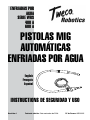
SAFETY AND OPERATING
INSTRUCTIONS
WATER-COOLED
AUTOMATION
MIG GUNS
English
Français
Español
WATER-COOLED
WRS SERIES
400 AMP
600 AMP

WE APPRECIATE YOUR BUSINESS!
Congratulations on your new Tweco
®
Robotics product. We are proud
to have you as our customer and will strive to provide you with the
best service and reliability in the industry. This product is backed
by our extensive warranty and worldwide service network. To locate
your nearest distributor or service agency call 800-426-1888, or visit
us on the web at www.tweco.com.
This Manual has been designed to instruct you on the correct
installation and use of your Tweco
®
Robotics product. Your satisfaction
with this product and its safe operation is our ultimate concern.
Therefore, please take the time to read the entire manual, especially
the Safety Precautions. They will help you to avoid potential hazards
that may exist when working with this product.
YOU ARE IN GOOD COMPANY!
The Brand of Choice for Contractors and Fabricators Worldwide.
Tweco
®
Robotics is a Global Brand of Welding Products for Thermadyne
Industries Inc. We manufacture and supply to major welding industry
sectors worldwide including; Manufacturing, Construction, Mining,
Automotive, Aerospace, Engineering, Rural and DIY/Hobbyist.
We distinguish ourselves from our competition through market-
leading, dependable products that have stood the test of time. We
pride ourselves on technical innovation, competitive prices, excellent
delivery, superior customer service and technical support, together
with excellence in sales and marketing expertise.
Above all, we are committed to develop technologically advanced
products to achieve a safer working environment within the welding
industry.

i
WARNINGS
Read and understand this entire Manual and your employer’s safety practices
before installing, operating, or servicing the equipment. While the information
contained in this Manual represents the Manufacturer’s judgment, the Manufacturer
assumes no liability for its use.
Water-Cooled Automation MIG Guns
Safety and Operating Instructions
Instruction Guide Number: 89200005
Published by:
Thermadyne
®
Industries, Inc.
2800 Airport Rd.
Denton, TX. 76208
(940) 566-2000
www.tweco.com
U.S. Customer Care: (800) 426-1888
International Customer Care: (905) 827-9777
Copyright © 2008 Thermadyne Industries, Inc. All rights reserved.
Reproduction of this work, in whole or in part, without written permission of the publisher is
prohibited.
The publisher does not assume and hereby disclaims any liability to any party for any loss
or damage caused by any error or omission in this Manual, whether such error results from
negligence, accident, or any other cause.
Publication Date: November 3, 2008
Record the following information for Warranty purposes:
Where Purchased:
Purchase Date:
Equipment Serial #:

ii
Table of Contents
SECTION 1: INTRODUCTION .................................................................................. 1-1
1.01 How to Use this Manual ................................................................
1-1
1.02 Receipt of Equipment ....................................................................
1-1
SECTION 2: SAFETY PRECAUTIONS .....................................................................
2-2
SECTION 3: MIG GUN SPECIFICATIONS.................................................................3-5
3.01 MIG Gun Classification ..................................................................3-5
3.02 MIG Gun Part Number Identification .............................................
3-6
SECTION 4: MIG GUN INSTALLATION ....................................................................
4-7
4.01 Standard MIG Gun Installation ......................................................4-7
4.02 Direct Plug ....................................................................................
4-7
4.03 Conductor Tube Installation ..........................................................
4-8
SECTION 5: CONTACT TIPS ...................................................................................
5-9
5.01 Identification .................................................................................5-9
5.02 Replacement .................................................................................5-9
SECTION 6: WIRE CONDUIT .................................................................................
6-10
6.01 Identification ...............................................................................6-10
6.02 Removal ......................................................................................6-10
6.03 Installation ..................................................................................
6-11
6.04 Bronze Jump Liner ......................................................................6-11
6.05 Connecting Water Line to Tweco Watercooler .............................
6-11
SECTION 7: TROUBLESHOOTING .........................................................................
7-12
SECTION 8: REPLACEMENT PARTS ..................................................................... 8-14
8.01 MIG Gun Parts Listing .................................................................8-14
8.02 Consumable Parts Listing ...........................................................
8-18
SECTION 9: STATEMENT OF WARRANTY ............................................................
9-20

SAFETY AND OPERATING INSTRUCTIONS
1-189200005 Introduction
SECTION 1:
INTRODUCTION
1.01 HOW TO USE THIS MANUAL
Information necessary to perform maintenance and service is contained in this manual. This
information is intended for use by technicians or personnel qualified to repair and service this
equipment. The information contained in this document, including performance specifications,
is subject to change without notice. To ensure safe operation, read the entire manual, including
the chapters on safety precautions and warnings.
Throughout this manual, the words WARNING, CAUTION, and NOTE may appear. Pay particular
attention to the information provided under these headings. These special annotations are
easily recognized as follows:
NOTE
NOTE conveys installation, operation, or maintenance information which is
important but not hazard-related.
CAUTION
CAUTION indicates a potentially hazardous situation which, if not avoided, may
result in injury.
WARNING
WARNING indicates a potentially hazardous situation which, if not avoided, could
result in death or serious injury.
1.02 RECEIPT OF EQUIPMENT
When you receive the equipment, check it against the invoice to make sure it is complete and
inspect the equipment for possible damage due to shipping. If there is any damage, notify the
carrier immediately to file a claim. Furnish complete information concerning damage claims
or shipping errors to the location in your area, listed on the back cover of this manual. Include
a full description of the parts in error.
If you want additional or replacement copies of this CD, please contact Tweco
®
Robotics at the
address and phone number in your area listed on the back cover of this manual. Include the
Manual number (from page i) and CD part number, CDROBOTICS.

2-2
SAFETY AND OPERATING INSTRUCTIONS
89200005Safety Precautions
SECTION 2:
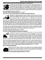
SAFETY PRECAUTIONS
WARNING
SERIOUS INJURY OR DEATH may result if welding and cutting equipment is
not properly installed, used, and maintained. Misuse of this equipment and other
unsafe practices can be hazardous. The operator, supervisor, and helper must read
and understand the following safety warnings and instructions before installing
or using any welding or cutting equipment, and be aware of the dangers of the
welding or cutting process. Training and proper supervision are important for a
safe work place. Keep these instructions for future use. Additional recommended
safety and operating information is referenced in each section.
WARNING
This product contains chemicals, including lead, or otherwise produces chemicals
known to the State of California to cause cancer, birth defects and other
reproductive harm. Wash hands after handling. (California Health & Safety Code
§ 25249.5 et seq.)
ELECTRIC SHOCK CAN CAUSE INJURY OR DEATH
Install and maintain equipment in accordance with the National Electrical Code
(NFPA 70) and local codes. Do not service or repair equipment with power on.
Do not operate equipment with protective insulators or covers removed. Service
or repair to equipment must be done by qualified and/or trained personnel
only.
Do not contact electrically live parts. Always wear dry welding gloves that are in good condition.
Aluminized, protective clothing can become part of the electrical path. Keep oxygen cylinders,
chains, wires, ropes, cranes, and hoists away from any part of the electrical path. All ground
connections must be checked periodically to determine if they are mechanically strong, and
electrically adequate for the required current. When engaged in AC welding/cutting under wet
conditions or where perspiration is a factor, the use of automatic controls for reducing the no
load voltage is recommended to reduce shock hazards. Accidental contact must be prevented
when using open circuit voltage exceeding 80 volts AC, or 100 volts DC by adequate insulation
or other means. When welding is to be suspended for any length of time, such as during lunch
or overnight, all electrode holders and electrodes should be removed from the electrode holder
and the power supply should be turned off to prevent accidental contact. Keep MIG guns,
electrode holders, Tig torches, Plasma torches, and electrodes away from moisture and water.
See safety and operating references 1, 2, and 8.

SAFETY AND OPERATING INSTRUCTIONS
2-389200005
SMOKE, FUMES, AND GASES CAN BE DANGEROUS TO YOUR HEALTH
Ventilation must be adequate to remove smoke, fumes, and gases during operation
to protect operators and others in the area. Vapors of chlorinated solvents can
form the toxic gas “Phosgene” when exposed to ultraviolet radiation from an
electric arc. All solvents, degreasers, and potential sources of these vapors must
be removed from the operating area. Use air-supplied respirators if ventilation
is not adequate to remove all fumes and gases. Oxygen supports, and vigorously accelerates fire
and should never be used for ventilation.
See safety and operating references 1, 2, 3, and 4.
ARC RAYS, HOT SLAG, AND SPARKS CAN INJURE EYES AND BURN SKIN
Welding and cutting processes produce extreme localized heat and strong
ultraviolet rays. Never attempt to weld/cut without a federally compliant welding
helmet with the proper lens. A number 12 to 14 shade filter lens provides the
best protection against arc radiation. When in a confined area, prevent the
reflected arc rays from entering around the helmet. Approved shielding curtains
and appropriate goggles should be used to provide protection to others in the surrounding area.
Skin should be protected from arc rays, heat, and molten metal. Always wear protective gloves
and clothing. All pockets should be closed and cuffs sewn shut. Leather aprons, sleeves, leggings,
etc. should be worn for out-of-position welding and cutting, or for heavy operations using large
electrodes. Hightop work shoes provide adequate protection from foot burns. For added protection,
use leather spats. Flammable hair preparations should not be used when welding/cutting. Wear
ear plugs to protect ears from sparks. Where work permits, the operator should be enclosed in
an individual booth painted with a low reflective material such as zinc oxide.
See safety and operating references 1, 2, and 3.
WELDING SPARKS CAN CAUSE FIRES AND EXPLOSIONS
Combustibles reached by the arc, flame, flying sparks, hot slag, and heated
materials can cause fire and explosions. Remove combustibles from the work
area and/or provide a fire watch. Avoid oily or greasy clothing as a spark may
ignite them. Have a fire extinguisher nearby, and know how to use it. If welding/
cutting is to be done on a metal wall, partition, ceiling, or roof, precautions must
be taken to prevent ignition of nearby combustibles on the other side. Do not
weld/cut containers that have held combustibles. All hollow spaces, cavities, and containers
should be vented prior to welding/cutting to permit the escape of air or gases. Purging with inert
gas is recommended. Never use oxygen in a welding torch. Use only inert gases or inert gas
mixes as required by the process. Use of combustible compressed gases can cause explosions
resulting in personal injury or death. Arcing against any compressed gas cylinder can cause
cylinder damage or explosion. See safety and operating references 1, 2, 5, 7, and 8.
NOISE CAN DAMAGE HEARING
Noise from the air carbon-arc process can damage your hearing. Wear protective
hearing devices to ensure protection when noise levels exceed OHSA standards.
Adequate hearing protection devices must be worn by operators and surrounding
personnel to ensure personal protection against noise.
See safety and operating references 1, 2, and 6.
Safety Precautions

2-4
SAFETY AND OPERATING INSTRUCTIONS
89200005
SAFETY AND OPERATING REFERENCES
1. Code of Federal Regulations (OSHA) Section 29, Part 1910.95, 132, 133, 134, 139, 251,
252, 253, 254 and 1000. U.S. Government Printing Office, Washington, DC 20402.
2. ANSI Z49.1 “Safety in Welding and Cutting”.
3. ANSI Z87.1 “Practice for Occupational and Educational Eye and Face Protection”.
4. ANSI Z88.2. “Standard Practice for Respiratory Protection”. American National
Standards Institute, 1430 Broadway, New York, NY 10018.
5. AWS F4.1. “Recommended Safe Practices for Welding and Cutting Containers”.
6. AWS C5.3. “Recommended Practices for Air Carbon-Arc Gouging and Cutting”.
The American Welding Society, 550 NW Lejeune Rd., P.O. Box 351040, Miami, FL
33135.
7. NFPA 51B. “Fire Prevention in Cutting and Welding Processes”.
8. NFPA-7. “National Electrical Code”. National Fire Protection Association, Battery Park,
Quincy, MA 02269.
9. CSA W117.2. “Safety in Welding, Cutting and Allied Processes”. Canadian Standards
Association, 178 Rexdale Blvd., Rexdale, Ontario, Canada M9W 1R3.
Safety Precautions

SAFETY AND OPERATING INSTRUCTIONS
3-589200005
SECTION 3:
MIG GUN SPECIFICATIONS
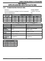
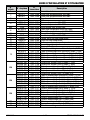
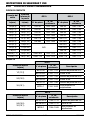
3.01 MIG GUN CLASSIFICATION
Process MIG/MAG welding
Voltage Class for Welding and Control Circuits L (up to 113 V peak)
Type of Cooling Water
MIG Gun Model
(AMP)
Duty Cycle (AMP)
10% 35% 60% 100%
350 440 420 400 380
400 470 440 420 400
600 700 660 630 600
The above duty cycles were established by testing under the following parameters:
Parameter MIG MAG
Electrode
Aluminum 3% to 5% Magnesium Mild (low carbon) Steel
Type of Voltage
D.C. D.C.
Shielding Gas Argon Argon/CO
2
Mixed Gas (80/20, 75/25)
Gas Flow Rate
30 CFH / 14.2 l/m 30 CFH / 14.2 l/m
Weld Material AIMg3 to AIMg5 Mild (low carbon) Steel
Gun Cable
Length
10 ft./3 m 15 ft./5 m
Electrode size
350 amp = .045"/1,2 mm
400 amp = 1/16"/1,6 mm
600 amp = 1/16"/1,6 mm
MIG Gun Specifications

3-6
SAFETY AND OPERATING INSTRUCTIONS
89200005
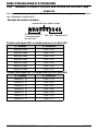
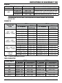
3.02 MIG GUN PART NUMBER IDENTIFICATION
NOTE
Tweco
®
Robotics MIG guns, as a general rule, have a specific nomenclature
incorporated within each part number to help determine the wire size of each
MIG gun.
Example Part Number:
WRS4043545
Water-Cooled,
Robotics Series
400 amp gun, 4 foot cable
.035-.045" Wire Capacity
Water-Cooled Robotic Series 400 AMP Guns
Part No. Stock No.
WRS400-3545 3044-1320
WRS404-3545 3044-1322
WRS406-3545 3044-1323
WRS408-3545 3044-1324
WRS410-3545 3044-1325
WRS412-3545 3044-1326
WRS415-3545 3044-1327
Water-Cooled Robotic Series 600 AMP Guns
Part No. Stock No.
WRS600-116 3064-1725
WRS604-116 3064-1366
WRS606-116 3064-1367
WRS608-116 3064-1368
WRS610-116 3064-1369
WRS612-116 3064-1370
WRS615-116 3064-1371
MIG Gun Specifications

SAFETY AND OPERATING INSTRUCTIONS
4-789200005
SECTION 4:
MIG GUN INSTALLATION
NOTE
Be certain that the end user (welder, operator, or helper) reads and understands
these instructions. The welder must also read Section 2, “Safety Precautions”.
WARNING
ELECTRICAL SHOCK MAY KILL.
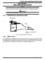
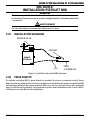
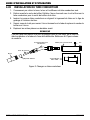
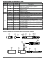
4.01 STANDARD MIG GUN INSTALLATION
POWER
SOURCE
WIRE FEEDER
GROUND
WORK PIECE
GUN
Figure 1: Standard MIG Gun Installation
4.02 DIRECT PLUG
Direct Plug MIG guns install by directly inserting the Tweco rear connector plug into the feeder
wire guide outlet and tightening the plug retaining screw. Automated MIG guns differ from
other MIG guns in that they do not have the control wire for trigger control. Rear connectors
are available for Lincoln, Miller, and Panasonic, in addition to adapter kits.
MIG Gun Installation

4-8
SAFETY AND OPERATING INSTRUCTIONS
89200005
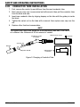
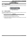
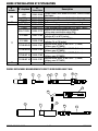
4.03 CONDUCTOR TUBE INSTALLATION
1. First, remove the nozzle, tip and diffuser from the used conductor tube.
2. Next, remove case cap. Loosen swivel nut with wrench, then pull the conductor tube
from the block and case.
3. Insert new conductor tube by aligning keyway on the tube with the guide pin inside
the block.
4. Tighten the swivel nut on the tube with a wrench, then replace case cap over the
nut.
5. Replace other front-end consumables.
NOTE
The conduit may need to be pulled out of the conductor tube area if the tube is
of a different size. Reference 6.02 for removal of conduit.
Nozzle
Contact Tip
Conductor Tube
Assembly
Spatter Shield
Robot Torch Case
Screw
Robot Block
Assembly
Figure 2: Changing a Conductor Tube
MIG Gun Installation

SAFETY AND OPERATING INSTRUCTIONS
5-989200005
SECTION 5:
CONTACT TIPS
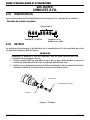
5.01 IDENTIFICATION
Identify contact tips by markings on the side of the tip, for example 14H-45 (1,2 mm).
Figure 3: Contact Tip
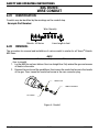
5.02 REPLACEMENT
The procedure for removal and installation of a contact tip is similar for all Tweco
®
Robotic
MIG Guns.
NOTE
Replace contact tip if hole is enlarged or deformed.
1. Select the correct contact tip according to the wire used.
2. Remove the nozzle from the gun to reveal the contact tip.
3. Remove the contact tip using pliers. Replace contact tip and tighten securely.
Contact Tips

6-10
SAFETY AND OPERATING INSTRUCTIONS
89200005
SECTION 6:
WIRE CONDUIT
6.01 IDENTIFICATION
Conduits may be identified by the markings on the conduit stop.
Example Part Number:
R44-3545-8
Robotic, 44 Series
Wire Capacity
Liner length in feet
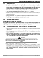
6.02 REMOVAL
The procedure for removal and installation of a wire conduit is similar for all Tweco
®
Robotic
MIG Guns.
NOTE
Replace kinked liner or if the hole is dirty or worn. Make sure the end of the
liner is smooth.
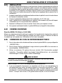
1. Lay the MIG Gun out on a table or floor in a straight line. Fully extend the gun and remove
all twists in the cable.
2. Remove the nozzle and the gas diffuser, then loosen the conduit set screw in the handle
of the gun. Then, loosen the conduit set screw in the rear connector plug.
SET SCREW
TWECO PLUG
CONDUIT ASSEMBLY
Figure 4: Conduit
Wire Conduit

SAFETY AND OPERATING INSTRUCTIONS
6-1189200005
6.03 INSTALLATION
1. Uncoil the conduit and lay it in a straight line. Remove any burrs or edges on the liner.
Insert the conduit into the rear connector plug. Push the conduit into the gun with short
strokes without kinking (bending) the liner. If the conduit hangs up, twist the conduit
counterclockwise or gently whip the cable while applying pressure to the conduit.
2. When the conduit is completely in the gun, tighten the rear conduit set screw.
3. Trim the conduit extending from the conductor tube to 1/2"(12,6 mm).
4. File the trimmed conduit end to remove burrs that could interfere with wire feeding or
catch on the diffuser.
5. Replace the diffuser and contact tip. Tighten securely, then replace the nozzle.
6. The MIG gun is now ready to be reinstalled on the feeder.
6.04 BRONZE JUMP LINER
Part No. AWC44-116 (Stock No. 1644-1085)
Using a jump liner improves arc starts and provides an improved current transfer between the
contact tip and aluminum wire. The jump liner can be used for wear issues found inside the
conductor tube area caused by the liner when using stainless steel wires.
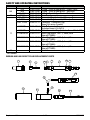
6.05 CONNECTING WATER LINE TO TWECO WATERCOOLER
1. Attach the rear blue coolant inlet hose on the MIG gun to the pump connection labeled
“WATER OUT”.
2. Attach the rear red coolant outlet hose on the MIG gun to the sight glass connection
labeled “WATER IN”.
3. Use a minimum water supply of 3/4 gallons/minute (2.84 liters/minute) during
operation. If possible, install the water supply to run when the power source is turned
“on” to avoid damage to torch and/or cable assembly.
CAUTION
Operating a water-cooled torch and cable assembly without water or with restricted
flow will result in damage to the cable assembly.
NOTE
Do not exceed coolant temperature of 155ºF (60ºF).
4. Incorporating a flow switch on water-cooled assemblies is recommended to avoid
catastrophic failure and production loss. For best results, place the flow switch in
line with the water-cooled gun outlet hose. The circuit functions as an emergency
stop, normally-closed circuit. When water flows at .25 gallons/minute or more, the
circuit is closed.
Wire Conduit

7-12
SAFETY AND OPERATING INSTRUCTIONS
89200005
SECTION 7:
TROUBLESHOOTING
Contact tips and nozzles should be cleaned frequently. Spatter buildup may cause bridging
between the nozzle and tip. This could cause electrical shorting between the nozzle and
workpiece as well as poor or improper gas flow.
Regularly inspect the conductor tube, handle, cablehose, and other parts of the MIG gun for
abrasion, cuts, or undue wear. Replace or repair any parts found deficient.
Problem Possible Cause Corrective Action
Wire feed
inconsistent or not
smooth
1. Loose contact tip or diffuser. 1. Tighten contact tip and diffuser
plier-tight.
2. Excessively worn contact tip. 2. Replace contact tip.
3. Spatter buildup on end of
contact tip.
3. Clean or replace contact tip.
4. Sharp bends or kinks in
conduit.
4. Straighten or replace conduit.
5. Dirty or plugged conduit. 5. Replace conduit.
6. Conduit pulled back from
diffuser.
6. Reposition conduit and tighten
front set screw.
7. Machine improperly adjusted. 7. Reset machine as per machine
and wire manufacturer’s
recommendations.
MIG gun running
hot.
1. Loose contact tip or diffuser. 1. Tighten contact tip and diffuser
plier-tight.
2. Loose power connections. 2. Inspect complete gun for loose
connections and repair.
3. Loose or undersized ground
cable or ground clamp.
3. Tighten or replace as required.
4. Operating gun above
recommended amperage
rating.
4. Readjust machine to correct
setting for size of gun being
used.
Porous weld
1. Poor or improper gas flow. 1. Check gas flow out of gun
nozzle. Check for leaks or
restrictions in gas hoses and
connections.
2. Dirty or contaminated wire. 2. Change wire.
3. Base metal contaminated. 3. Replace base metal.
Troubleshooting

SAFETY AND OPERATING INSTRUCTIONS
7-1389200005 Troubleshooting
THIS PAGE LEFT BLANK INTENTIONALLY

8-14
SAFETY AND OPERATING INSTRUCTIONS
89200005
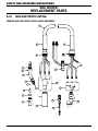
SECTION 8:
REPLACEMENT PARTS
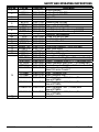
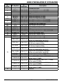
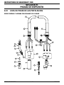
8.01 MIG GUN PARTS LISTING
WRS400 AND 600 SERIES WITH CABLE ASSEMBLY
16
15
16
10
14
12
13
12
11
16
18
17
10
1
2
3
4
5
6
7
8
9
Replacement Parts

SAFETY AND OPERATING INSTRUCTIONS
8-1589200005
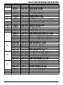
Item No. Part No. Stock No. Description
1 -- -- Nozzle Assembly
2
WC24-1 1244-1009 Spatter Shield 400 AMP
WC26-1 1264-1009 Spatter Shield 600 AMP
3 -- -- Contact Tip
4 -- -- Diffuser
5
WC34-R 2044-1034 Pressure Ring 400 AMP
WC36-R 2064-1036 Pressure Ring 600 AMP
NS* 224S 2064-2059 O-Ring 400 and 600 AMP
6
WCS34-H 1344-1844 400 AMP
WCS36-H 1344-1145 Sealed Conductor Tube Housing 500 AMP
7 -- -- Conductor Tube Assembly
NS 224S 2064-2059 O-Ring 400 and 600 AMP
8 WR6H 2066-2006 Conductor Tube Nut Cover
9 WR66-N 2066-2066 Conductor Tube Nut
10 WR6H 2066-2600 Case With Strain Relief Cap
11 WR106 2066-2106 Torch Block Assembly
12 WC146-6 2064-2146 Strain Relief (Front)
13
WC600-4 1764-2107 Cable Assembly With Fittings 4ft. (1,22m)
WC600-6 1764-2108 Cable Assembly With Fittings 6ft. (1,83m)
WC600-8 1764-2109 Cable Assembly With Fittings 8ft. (2,44m)
WC600-10 1764-2101 Cable Assembly With Fittings 10ft. (3m)
WC600-12 1764-2102 Cable Assembly With Fittings 12ft. (4m)
WC600-15 1764-2103 Cable Assembly With Fittings 15ft. (5m)
NS
WC604-WH 1764-2137 Water Inlet Hose 4ft. (1,22m)
WC606-WH 1764-2138 Water Inlet Hose 6ft. (1,83m)
WC608-WH 1764-2139 Water Inlet Hose 8ft. (2,44m)
WC610-WH 1764-2131 Water Inlet Hose 10ft. (3m)
WC612-WH 1764-2132
Water Inlet Hose 12ft. (4m)
WC615-WH 1764-2133 Water Inlet Hose 15ft. (5m)
NS
WC604-PC 1764-2117 Power Cable Assembly 4ft. (1,22m)
WC606-PC 1764-2118 Power Cable Assembly 6ft. (1,83m)
WC608-PC 1764-2119 Power Cable Assembly 8ft. (2,44m)
WC610-PC 1764-2111 Power Cable Assembly 10ft. (3m)
WC612-PC 1764-2112 Power Cable Assembly 12ft. (4m)
WC615-PC 1764-2113 Power Cable Assembly 15ft. (5m)
NS
WC604-GH 1764-2127 Gas Hose Assembly 4ft. (1,22m)
WC606-GH 1764-2128 Gas Hose Assembly 6ft. (1,83m)
WC608-GH 1764-2129 Gas Hose Assembly 8ft. (2,44m)
WC610-GH 1764-2121 Gas Hose Assembly 10ft. (3m)
WC612-GH 1764-2122 Gas Hose Assembly 12ft. (4m)
WC615-GH 1764-2123 Gas Hose Assembly 15ft. (5m)
NS 400LK-J 2044-2100 Outer Jacket - Sold Per Ft.
14 WC603-WH 1764-2130 Outer Water Hose 3ft. (900mm)
15 WC6-170H 2064-2171 Rear Connector Block Assembly
Replacement Parts

8-16
SAFETY AND OPERATING INSTRUCTIONS
89200005
Item No. Part No. Stock No. Description
NS
45B 2050-2045 O-Ring - Front & Rear Block - Power Cable
46B 2062-2046 O-Ring - Front & Rear Block - Gas Hose
35-40-1 2000-2040 O-Ring - Front & Rear Block - Water Hose
16 WR6C 2064-2006 Rear Case Assembly
17
350-174H 2035-2110 Connector Plug Assembly 400amp - Tweco
®
176SH 2066-2177 Connector Plug Assembly 600amp - Tweco
350-174PH 2035-2172 Panasonic
®
Connector Plug
(Uses R44 series Conduit)
R176MH 2060-2184 Miller
®
Connector Plug
(Includes Items #14 & #15)
R174MH 2035-2109 Miller Connector Plug (Includes Items #14 & #15)
R175M-N045 2050-2181 Miller Plug Nipple, .045" (1,0mm) Wire
(Use w/R176MH)
R174M-N045 2040-2192 Miller Plug Nipple, .045" (1,0mm) Wire
(Use w/R174MH)
R175M-N116 2050-2182 Miller Plug Nipple, .062" (1,6mm) WIre
(Use w/R176MH)
R174M-N116 2040-2191 Miller Plug Nipple, .062" (1,6mm) Wire
(Use w/R174MH)
18 -- -- Conduit
* Not Shown
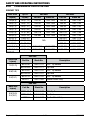
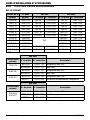
WRS400 AND 600 DIRECT PLUG REPLACEMENT PARTS
W
C
2
4
-
6
2
T
w
e
c
o
1
2
3
7
8
9
10
11
12
14
13
16
15
4
5
6
Replacement Parts
La page est en cours de chargement...
La page est en cours de chargement...
La page est en cours de chargement...
La page est en cours de chargement...
La page est en cours de chargement...
La page est en cours de chargement...
La page est en cours de chargement...
La page est en cours de chargement...
La page est en cours de chargement...
La page est en cours de chargement...
La page est en cours de chargement...
La page est en cours de chargement...
La page est en cours de chargement...
La page est en cours de chargement...
La page est en cours de chargement...
La page est en cours de chargement...
La page est en cours de chargement...
La page est en cours de chargement...
La page est en cours de chargement...
La page est en cours de chargement...
La page est en cours de chargement...
La page est en cours de chargement...
La page est en cours de chargement...
La page est en cours de chargement...
La page est en cours de chargement...
La page est en cours de chargement...
La page est en cours de chargement...
La page est en cours de chargement...
La page est en cours de chargement...
La page est en cours de chargement...
La page est en cours de chargement...
La page est en cours de chargement...
La page est en cours de chargement...
La page est en cours de chargement...
La page est en cours de chargement...
La page est en cours de chargement...
La page est en cours de chargement...
La page est en cours de chargement...
La page est en cours de chargement...
La page est en cours de chargement...
La page est en cours de chargement...
La page est en cours de chargement...
La page est en cours de chargement...
La page est en cours de chargement...
La page est en cours de chargement...
La page est en cours de chargement...
La page est en cours de chargement...
La page est en cours de chargement...
La page est en cours de chargement...
La page est en cours de chargement...
La page est en cours de chargement...
La page est en cours de chargement...
La page est en cours de chargement...
La page est en cours de chargement...
La page est en cours de chargement...
La page est en cours de chargement...
La page est en cours de chargement...
La page est en cours de chargement...
-
 1
1
-
 2
2
-
 3
3
-
 4
4
-
 5
5
-
 6
6
-
 7
7
-
 8
8
-
 9
9
-
 10
10
-
 11
11
-
 12
12
-
 13
13
-
 14
14
-
 15
15
-
 16
16
-
 17
17
-
 18
18
-
 19
19
-
 20
20
-
 21
21
-
 22
22
-
 23
23
-
 24
24
-
 25
25
-
 26
26
-
 27
27
-
 28
28
-
 29
29
-
 30
30
-
 31
31
-
 32
32
-
 33
33
-
 34
34
-
 35
35
-
 36
36
-
 37
37
-
 38
38
-
 39
39
-
 40
40
-
 41
41
-
 42
42
-
 43
43
-
 44
44
-
 45
45
-
 46
46
-
 47
47
-
 48
48
-
 49
49
-
 50
50
-
 51
51
-
 52
52
-
 53
53
-
 54
54
-
 55
55
-
 56
56
-
 57
57
-
 58
58
-
 59
59
-
 60
60
-
 61
61
-
 62
62
-
 63
63
-
 64
64
-
 65
65
-
 66
66
-
 67
67
-
 68
68
-
 69
69
-
 70
70
-
 71
71
-
 72
72
-
 73
73
-
 74
74
-
 75
75
-
 76
76
-
 77
77
-
 78
78


Tweco Robotics WRS Series 400 AMP 600 AMP Water-Cooled Automation Mig Guns Manuel utilisateur
- Taper
- Manuel utilisateur
dans d''autres langues
Documents connexes
-
 Tweco Robotics QRC-3000LS QRC-3000IO Ultrasonic Nozzle Cleaning Station Manuel utilisateur
-
 Tweco Robotics QRM-100 Anti-Spatter Mist Applicator Guide d'installation
-
 Tweco Robotics QRM-3 Solenoid Valve Assembly Guide d'installation
-
 Tweco Robotics QFA600 QFW600 Quick Fixed Automation Direct Plug Torches Guide d'installation
-
 Tweco Robotics Quick Robotic Torch Guide d'installation
-
 Tweco Robotics Quick Fixed Automation Series Torches Guide d'installation
-
Tweco Robotics Light Weight Quick Robotics Torch Guide d'installation


Autres documents
-
 Tweco Air-Cooled 350 AMP 450 AMP Water-Cooled 400 AMP 500 AMP PulseMaster™ Mig Gun Manuel utilisateur
-
 Tweco Welding and Cutting Operations Manuel utilisateur
-
Tweco Air-Cooled Mig Guns Manuel utilisateur
-
 Tweco Classic No. Series Mig Guns with Velocity Consumables Manuel utilisateur
-
 Tweco Classic No. Series Mig Guns Manuel utilisateur
-
 Tweco Classic Serial No. Mig Guns Manuel utilisateur
-
 Tweco Classic No. Series Mig Guns Manuel utilisateur
-
 Tweco Classic No. Series Mig Guns Manuel utilisateur
-
ESAB Firepower Air Cooled Mig Gun 180 AMP and 220 AMP Manuel utilisateur
-
Tweco Tweco Spray Master MIG Guns with VELOCITY2 Manuel utilisateur


