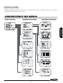
Marmitek TLV9600 Le manuel du propriétaire
- Catégorie
- Lecteurs de cassettes
- Taper
- Le manuel du propriétaire

MARMITEK
TIME LAPSE RECORDER
TLV 9600
091202-UK • TLV9600
COPYRIGHT ALL RIGHTS RESERVED MARMITEK
2002
OWNERS MANUAL
BEDIENUNGSANLEITUNG
NOTICE D’UTILISATION
GEBRUIKSAANWIJZING


PRECAUTIONS
ENGLISH
• Read carefully through this manual to familiarize yourself with
this high-quality Time Lapse VCR.
• Make sure the rating of your household electricity supply
matches that shown on the back of the Time Lapse VCR.
• During the power off, the unit is always connected to the mains.
Unplug the unit from the wall outlet if it is not to be used for
several days or more.
Do not ...
... expose the Time Lapse VCR to high levels of humidity and heat,
to avoid the risk of fire and electric shock.
... open the Time Lapse VCR. Have a qualified technician carry out
repairs.
... connect the Time Lapse VCR to the power supply if you have just
moved it from a cold to warm environment. This can result in
condensation inside the recorder and cause serious damage to
the machine and cassettes. Wait around two hours to allow it to
reach room temperature.
Make sure ...
... the Time Lapse VCR is placed on a steady, flat surface.
... you place the Time Lapse VCR where there is good ventilation all
around.
... you clean the Time Lapse VCR only with a soft, lint-free cloth; do
not use aggressive or alcohol-based cleaning agents.
... you disconnect the power supply if the Time Lapse VCR appears
to be working incorrectly, is making an unusual sound, has a
strange smell, has smoke emitting from it or liquids have got
inside it. Have a qualified technician check the recorder.
... you disconnect the power supply and aerial if you will not be
using the Time Lapse VCR for a long period or during a
thunderstorm.
For your own safety!
• There are no components in this Time Lapse VCR you
can service or repair yourself.
• Do not open the case of the Time Lapse VCR. Only
allow qualified personnel to repair or service your set.
• This Time Lapse VCR is designed for continuous
operation. Switching it off does not disconnect it from
the mains (stand-by). To disconnect it from the mains,
you have to unplug it.
• Recording any copyright protected material may infringe
a copyright.
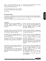
Precautions

IMPORTANT SAFEGUARDS
1. READ INSTRUCTIONS - All the safety and operating instructions should be read before the unit is operated.
2. RETAIN INSTRUCTIONS - The safety and operating instructions should be retained for future reference.
3. HEED WARNINGS - All warnings on the unit and in the operating instructions should be adhered to.
4. FOLLOW INSTRUCTIONS - All operating and use instructions should be followed.
5. CLEANING - Unplug this unit from the wall outlet before cleaning. Do not use liquid cleaners or aerosol cleaners.
Use a damp cloth for cleaning.
6. ATTACHMENTS - Do not use attachments not recommended by the unit’s manufacturer as they may cause
hazards.
7. WATER AND MOISTURE - Do not use this unit near water - for example, near a bathtub, washbowl, kitchen sink
or laundry tub; in a wet basement; nor near a swimming pool in an unprotected outdoor installation, or any area
which is classified as a wet location.
8. ACCESSORIES - Do not place this unit on an unstable stand, tripod, bracket or mount. The unit may fall, causing
serious injury to a person and serious damage to the unit. Use only with a stand, tripod,
bracket nor mount recommended by the manufacturer or sold with the unit. Any mounting of
the unit should follow the manufacturer’s instructions and should use a mounting accessory
recommended by the manufacturer. An appliance and cart combination should be moved with
care. Quick stops, excessive force, and uneven surfaces may cause the appliance and cart
combination to overturn.
9. VENTILATION - Openings in the enclosure, if any, are provided for ventilation and to ensure reliable operation
of the unit and to protect it from overheating. These openings must not be blocked or covered. This unit should
never be placed in a built-in installation unless proper ventilation is provided or the manufacturer's instructions
have been adhered to.
10. POWER SOURCES - This unit should be operated only from the type of power source indicated on the marking
label. If you are not sure of the type of power supply you plan to use, consult your appliance dealer or local
power company. For units intended to operate from battery or other sources, refer to the operating instructions.
CAUTION
RISK OF ELECTRIC SHOCK
DO NOT OPEN
CAUTION: TO REDUCE THE RISK OF ELECTRIC SHOCK, DO NOT REMOVE
COVER (OR BACK). NO USER-SERVICEABLE PARTS INSIDE.
REFER SERVICING TO QUALIFIED SERVICE PERSONNEL.
The lightning flash with arrowhead symbol, within an equilateral triangle, is intended to
alert the user to the presence of uninsulated “dangerous voltage” within the product’s
enclosure that may be of sufficient magnitude to constitute a risk of electric shock.
The exclamation point within an equilateral triangle is intended to alert the user to the
presence of important operating and servicing instructions in the literature accompanying
the appliance.
WARNING : TO REDUCE THE RISK OF FIRE OR ELECTRIC SHOCK, DO NOT EXPOSE THIS
APPLIANCE TO RAIN OR MOISTURE.
CAUTION : TO PREVENT ELECTRIC SHOCK, MATCH WIDE BLADE OF PLUG TO WIDE SLOT,
FULLY INSERT.
Important Safeguards

IMPORTANT SAFEGUARDS
ENGLISH
11. GROUNDING OR POLARIZATION - This unit may be equipped with a polarized alternating-current line plug (a
plug having one blade wider than the other). This plug will fit into the power outlet only one way. This is a safety
feature. If you are unable to insert the plug fully into the outlet, try reversing the plug. If the plug should still fail to
fit, contact your electrician to replace your obsolete outlet. Do not defeat the safety purpose of the polarized
plug. Alternately, this unit may be equipped with a 3-wire grounding-type plug, having a third (grounding) pin.
This plug will only fit into a grounding-type power outlet. This is a safety feature. If you are unable to insert the
plug into the outlet, contact your electrician to replace your obsolete outlet. Do not defeat the safety purpose of
the grounding-type plug.
12. POWER-CORD PROTECTION - Power-supply cords should be routed so that they are not likely to be walked
on or pinched by items placed upon or against them, paying particular attention to cords and plugs, convenience
receptacles, and the point where they exit from the appliance.
13. POWER LINES - An outdoor system should not be located in the vicinity of overhead power lines or other
electric light or power circuits, or where it can fall into such power lines or circuits. When installing an outdoor
system, extreme care should be taken to keep from touching such power lines or circuits as contact with them
might be fatal. U.S.A models only - refer to the National Electrical Code Article 820 regarding installation of
CATV systems.
14. OVERLOADING - Do not overload outlets and extension cords as this can result in a risk of fire or electric
shock.
15. OBJECT AND LIQUID ENTRY - Do not push objects of any kind into this unit through openings as they may
touch dangerous voltage points or short-out parts that could result in a fire or electric shock. Never spill liquid of
any kind on the unit.
16. SERVICING - Do not attempt to service this unit yourself as opening or removing covers may expose you to
dangerous voltage or other hazards. Refer all servicing to qualified service personnel.
17. DAMAGE REQUIRING SERVICE - Unplug the unit from the wall outlet and refer servicing to qualified service
personnel under the following conditions:
a. When the power-supply cord or plug is damaged.
b. If liquid has been spilled, or objects have fallen into the unit.
c. If the unit has been exposed to rain or water.
d. If the unit does not operate normally by following the operating instructions. Adjust only those controls that are
covered by the operating instructions, as an adjustment of other controls may result in damage and will often
require extensive work by a qualified technician to restore the unit to its normal operation.
e. If the unit has been dropped or the cabinet has been damaged.
f. When the unit exhibits a distinct change in performance - this indicates a need for service.
18. REPLACEMENT PARTS - When replacement parts are required, be sure the service technician uses replacement
parts specified by the manufacturer or have the same characteristics as the original part. Unauthorized substitutions
may result in fire, electric shock or other hazards.
19. SAFETY CHECK - Upon completion of any service or repairs to this unit, ask the service technician to perform safety
checks to determine that the unit is in proper operating condition.
20. COAX GROUNDING - If an outside cable system is connected to the unit, be sure the cable system is
grounded. U.S.A models only - Section 810 of the National Electric Code, ANSI/NFPA No.70-1981, provides
information with respect to proper grounding of the mount and supporting structure, grounding of the coax to a
discharge unit, size of grounding conductors, location of discharge unit, connection to grounding electrodes and
requirements for the grounding electrode.
21. LIGHTNING - For added protection of this unit during a lightning storm or when it is left unattended and unused
for long period of time, unplug power cord from the wall.
Polarized Attachment Plug Marking - for CNL use only.
CAUTION - TO PREVENT ELECTRIC SHOCK, MATCH WIDE BLADE OF PLUG TO WIDE SLOT,
FULLY INSERT

CONTENTS
Locations of controls and indicators...................................................................................................... 1
Front panel.......................................................................................................................... 1
Digital display..................................................................................................................... 2
Display of operating conditions ........................................................................................ 3
Back panel........................................................................................................................... 4
Remote control.................................................................................................................... 5
Connections ......................................................................................................................................... 6
Video Cassettes Tapes ........................................................................................................................... 7
Types of on-screen displays and Display Sequence ................................................................................ 8
Setting the Clock ............................................................................................................................... 10
Changing the on-screen display .......................................................................................................... 12
Normal Recording .............................................................................................................................. 14
Program Timer Recording ................................................................................................................... 15
Alarm Recording ................................................................................................................................ 19
Panic Recording ................................................................................................................................. 20
Series(Link) Recording ....................................................................................................................... 20
Autorepeat Recording ........................................................................................................................ 22
Normal Playback ................................................................................................................................ 23
Normal Playback .............................................................................................................. 23
Tracking Control ...............................................................................................................23
Audio Playback .................................................................................................................23
Special Playback ................................................................................................................................ 24
Picture Search .................................................................................................................. 24
Still Image ........................................................................................................................ 24
Vertical Lock Control ........................................................................................................ 24
Slow ................................................................................................................................. 24
Recording Check .............................................................................................................. 24
Time/Date Search ............................................................................................................ 25
Alarm Search ...................................................................................................................25
Alarm Scan ....................................................................................................................... 26
Zero Search....................................................................................................................... 26
Other functions ................................................................................................................................. 27
Tape Counter (Zero Search) .............................................................................................. 27
Setting the Security Lock (Set Lock) ................................................................................ 28
Setting the SW Out Terminal Output ............................................................................... 28
Setting the Buzzer ............................................................................................................ 29
Changing the Alarm Recording Times ............................................................................. 30
Checking the Power Loss Times ...................................................................................... 30
Checking Usage Duration ................................................................................................ 31
Setting In/Out Terminals .................................................................................................. 31
Maintenance ...................................................................................................................................... 34
Troubleshooting Guide ....................................................................................................................... 35
Specifications ..................................................................................................................................... 37
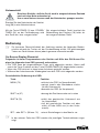
Contents

1
ENGLISH
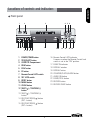
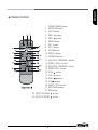
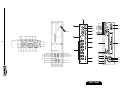
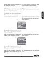
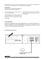
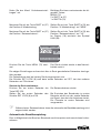
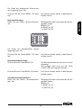
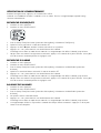
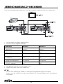
Locations of controls and indicators
1 POWER/TIMER button
2 STOP/EJECT button
3 CASSETTE Compartment
4 REW button
5 PLAY button
6 FF button
7 Remote Control LOCK switch
8 SET LOCK switch
9 RESET button
10 MENU button
11 CLEAR button
12 SHIFT( ) / TRACKING (-)
button
13 SHIFT( ) / TRACKING (+)
button
14 REC/PLAY SPEED( ) button
(SET - button)
15 REC/PLAY SPEED( ) button
(SET + button)
1 POWER/TIMER button
2 STOP/EJECT button
3 CASSETTE Compartment
4 REW button
5 PLAY button
6 FF button
7 Remote Control LOCK switch
8 SET LOCK switch
9 RESET button
10 MENU button
11 CLEAR button
12 SHIFT( ) / TRACKING (-)
button
14
12 3 6
7
45
89
11 15 16
12 13 18
19
20
10
21 22 23 24
17
Front panel
16 Remote Control LOCK indicator
It comes on when the Remote Control Lock
switch is set to the "ON" position.
17 PANIC IN indicator
18 DISPLAY window
19 DISPLAY button
20 COUNTER/CLOCK/ALARM button
21 AUDIO ON button
22 PAUSE/STILL button
23 RECORD button
24 RECORD CHECK button

2
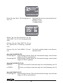
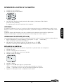
1 Repeat recording
It indicates that repeat recording is activated. When the tape reaches
its end, the unit will rewind and record over previously taped footage.
2 SET LOCK
It comes on when the SET LOCK sw is set to the “ON” position.
3 Timer recording
It appears when the timer is programmed.
4 Cassette status indicator
It illuminates when a tape is inserted.
5 REC indicator
It illuminates during recording and when TIMER REC is set to on.
6 CLOCK indicator
It indicates the current time.
7 COUNT indicator
It indicates the relative position on the tape.
8 ALARM indicator
It appears after the alarm mode is activated.
9 PF indicator
It indicates the existence of power failure.
10 Play / cue / review / still / slow
It indicates the tape operation.
11 TAB indicator
It appears when the tape does not have a security tab.
Digital Display

3
ENGLISH
12 LINK indicator
It appears when LINK (Series) REC is turned on.
13 Digit indicator
It indicates clock, tape counter, and tape speed during
playback/recording.
14 Mode display
• TAPE COUNTER display (ex:10:HOUR,59:MINUTE)
- Maximum Hour : 19 - Maximum Minute : 59
• ALARM COUNTER display (ex: A:Alarm , 32:Alarm No.)
• PLAY/REC SPEED display (ex: 36H:Play/Recording Speed)
• TIME display (ex: 7:HOUR , 07:MINUTE)
• ERROR display (ex: E:Error , 04:Error No.)
- E-01 : The cassette cannot be loaded or unloaded.
- E-02 : The tape stops.
- E-03 : The drum can not rotate properly.
- E-04 : The tape is cut/broken.
• AUDIO ON display (ex: A:Audio , 18H:Play Speed)
Operation Mode Indicator
1 Record(REC) REC
2 Record pause (REC PAUSE) REC
3 Playback (PLAY)
4 Still image (STILL)
5 Fast forward (FF)
6 Rewind (REW)
7 CUE (CUE)
8 Review (REVIEW)
9 Slow (Pause Still + FF, Pause Still + REW)
Display of operating conditions

4
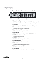
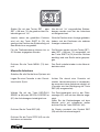
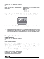
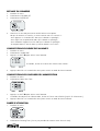
Back Panel
1 AC POWER CORD
2 WARNING OUT terminal
3 SERIES IN terminal
4 COM terminal
5 SERIES OUT terminal
6 SW OUT terminal
7 VIDEO OUT jack (BNC Type)
8 VIDEO IN jack (BNC Type)
9 AUDIO IN jack (RCA Type)
10 TAPE END terminal
11 PANIC IN terminal
12 COM terminal
13 ALARM OUT terminal
14 ALARM IN terminal
15 MIC(microphone input) jack
16 AUDIO OUT jack (RCA Type)

5
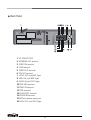
ENGLISH
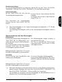
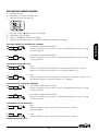
1 POWER (TIMER) button
2 AUDIO ON button
3 EJECT button
4 SHIFT button
5 SHIFT button
6 MENU button
7 SET - button
8 SET + button
9 CLEAR button
10 DISPLAY button
11 COUNTER button
12 PLAY/STILL TRACKING + button
13 PAUSE / STILL + button
14 PLAY/STILL TRACKING - button
15 PAUSE/STILL - button
16 STOP button
17 PLAY button
18 REW button
19 FF button
20 PAUSE / STILL button
21 REC CHECK button
22 REC button
23 REC/PLAY SPEED button
24 REC/PLAY SPEED button
Remote Control

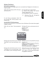
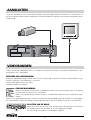
6
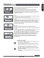
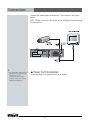
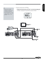
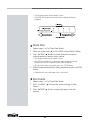
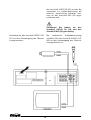
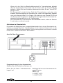
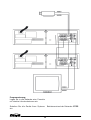
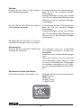
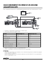
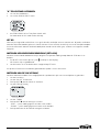
Connect the video camera and monitor TV as shown in the figure
below.
NOTE : Make sure to turn the power off on all devices before making
the connections.
✔
• For more details, please refer to
the manuals accompanying all
other devices. If the
connections are not made
properly, it may cause a fire or
damage the equipment.
Connections
Power Cord Installation
Insert the plug of the power cord into an outlet.

7
ENGLISH
Use only video cassette tapes bearing the logo.
This VCR was primarily designed for use with T-120 cassette tapes.
It is recommended to use T-120 VHS video cassette tapes for
optimal performance.
Handling Cassette Tapes
Cassette tapes should always be stored vertically in their cases,
away from high temperatures, magnetic fields, direct sunlight, dirt,
dust and locations subject to mold formation.
Do not tamper with the cassette mechanism.
Never touch the tape with your fingers.
Protect cassette tapes from shocks or strong vibrations.
To Protect your recordings
After having recorded a tape, if you wish to keep the recording, use
a flathead screwdriver to break off the erasure-prevention tab on the
cassette.
To record again on a tape without erasure-prevention tab, cover the
hole with adhesive tape.
Erasure-prevention tab
To prevent accidental erasure, remove the tab after
recording.
To record again, cover the hole with vinyl tape.
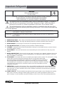
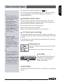
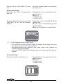
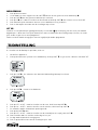
Loading
Place the cassette, label side up, in
the loading slot. Gently push the
center of the cassette until it is
loaded automatically.
Unloading
In STOP mode, press the EJECT button. The cassette is automatically
ejected.
✔
• If you try to record on a
cassette without the erasure-
prevention tab, the VCR will
eject the cassette.
• If the TIMER button is
pressed when a cassette
without the erasure-
prevention tab is loaded,
the VCR will eject the
cassette, the timer recording
indicator ( ) will start
flashing and a buzzer will
sound if “YES” is set in the
menu for buzzer.
✔
• When the cassette is
loaded, the cassette
indicator “ “ will light on
the display panel.
• The counter display will
switch to the reset counter
“0H 00M 00S” display on
the monitor screen. (“0H
00M 00S” on the display
panel.)
✔
• Do not insert any object in
the cassette loading slot, as
that may cause injury and
damage to the VCR.
• If your hand gets stuck in the
cassette loading slot, unplug
the power cord and consult
the dealer where the unit
was bought. Do not forcibly
pull the hand out as that
may cause severe injuries.
Video Cassettes Tapes

8
( NTSC )
( PAL )
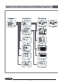
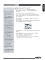
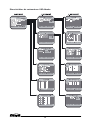
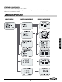
Types of on-screen displays and Display Sequence

9
ENGLISH
• Press the MENU button. (First
time)
• Press the SHIFT button to
move the arrow mark ( )
downward for the desired item.
• Press the SHIFT button to
select the desired item, then
the desired menu is displayed.
• Press the MENU button to
return to the normal screen
from the initial menu.
• If the VCR is in timer recording stand-by mode
(the ““ indicator is displayed on the display
panel), the on-screen displays will not be
available. First press the Power/Timer button,
to cancel the recording stand-by mode, then
proceed with the VCR programming. When
finished, press the Power/Timer button again
to return the VCR to timer recording stand-by
mode.
• When a menu is displayed, recording will not
be possible.
• Press the MENU button three times, the
setting procedure is now completed then the
normal screen is displayed.
• During recording or playback the menus
cannot be displayed.
• Press the SHIFT button
to select the desired item.
• Press the SET - (or +)
button to set or Press the
SHIFT button to select
“YES” or “NO”.
• Press the MENU button to
return to the initial menu.

10
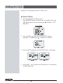
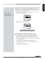
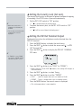
Example: To set the clock to April 12, 2000 at 9:30
Clock Setting
1 Turn the power on to all devices used.
2 Press the MENU button, the initial menu is displayed. Press the
SHIFT button to move the arrow mark ( ) located on “VCR
Mode Set”.
Initial MENU
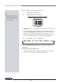
3 Press the SHIFT button, the VCR MODE SET menu is
displayed. The arrow mark ( ) is located in “Clock Set”.
4 Press the SHIFT button, the CLOCK SET menu is displayed.
5 Press the SET - (or +) button to set the hours (ex : 09), then press
the SHIFT button.
(NTSC
)
(PAL)
Setting the Clock

11
ENGLISH
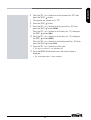
6 Press the SET - (or +) button to set the minutes (ex : 30), then
press the SHIFT button.
7 The seconds are already set to “00”.
8 Press the SHIFT button.
9 Press the SET - (or +) button to set the month (ex : 04), then
press the SHIFT button.
(NTSC)
Press the SET - (or +) button to set the day (ex : 12), then press
the SHIFT button.
(PAL)
10 Press the SET - (or +) button to set the day (ex : 12), then press
the SHIFT button.
(NTSC)
Press the SET - (or +) button to set the day month (ex : 04), then
press the SHIFT button.
(PAL)
11 Press the SET - (or +) button to set the year.
• The day of the week is set automatically.
12 Press the MENU button three times, the normal screen is
displayed.
• The setting procedure is now complete.

12
Selecting the Language
You can select the language -English, French, Spanish or German-
which is more convenient for you.
1 Turn the power on to all devices used.
2 Press the MENU button. The initial menu is displayed. The
arrow mark ( ) is located in “Language Set”.
3 Press the SHIFT button to select the desired language. OSD
(On-Screen Display) will display with the selected language.
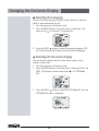
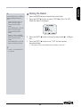
Selecting the On-screen Display
You can select to display the time, date, frame counter, alarm
counter, counter title.
1 Turn the power on to all devices used.
2 Press the MENU button. The initial menu is displayed. Press the
SHIFT ( ) button to move arrow mark ( ) to “VCR Mode
Set”.
3 Press the SHIFT button to select the VCR Mode Set, then the
VCR Mode Set menu is displayed.
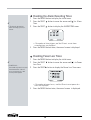
Changing the On-Screen Display

13
ENGLISH
4 Press the SHIFT button, until the arrow mark ( ) points
“Display set”.
5 Press the SHIFT button to select Display Set. Then the
DISPLAY SET menu is displayed.
6 Press the SET - (or +) button to set “YES” for the functions
described below.
Time ..............The time is displayed.
Date ..............The Month-Day-Year is displayed.
Frame Cnt......The number of frames is displayed.
Alarm Cnt......The number of alarms is displayed.
Counter .........The counter is displayed.
Title ...............The title is displayed.
• A maximum of 20 characters can be used. (alphabet, numbers,
space)
7 Press the SHIFT button to set the display position.
8 Press the SET - (or +) button to set the position of the time, date,
frame cnt. alarm cnt. to “L-Bottom (or R-Bottom).
• If one of 4 items is set, the position of 4 items is changed
identically.
9 Press the SET - (or +) button to set the position of counter, title
to “C-Top” (or “R-Top” or “L-Top”)
If one of 2 items is set, the position of 2 items is changed
identically.
L-Top / C-Top / R-Top
: Left Top / Center Top / Right Top
L-Bottom / R-Bottom
: Left Bottom / Right Bottom
10 Press the MENU button three times, the normal screen is
displayed.
The setting procedure is now complete.
✔
• The items for which “YES” is
set are recorded. The items for
which “NO” is set at step 6
above are not recorded.

14
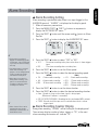
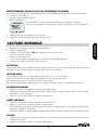
Normal Recording
1 Turn the power on to all devices used.
2 Load a cassette tape with erasure prevention tab in place.
3 Press the REC/PLAY SPEED (or ) button to set the recording
speed.
• The recording speed is displayed on-screen and on the display
panel.
• If you don’t want to record the recording speed, counter, title, time,
date etc, press the DISPLAY button, then start recording.
4 Press the REC button.
• The “REC” indicator is displayed on the display panel and recording
starts.
5 To stop recording, press the STOP button.
<Recording Speed>
✔
• If the Repeat Rec Set is set to
“NO” in the REC MODE SET
menu , recording will continue
to the end of the tape, then stop
and the tape will be ejected.
✔
• A tape recorded on this VCR
cannot be played back on
another make of time lapse
VCR.
• If you press on the REC button
and the loaded cassette has no
erasure-prevention tab, the VCR
will eject the cassette.
• During recording, the Menu
button will not function (the
menu cannot be accessed).
Record Pause
Recording can be interrupted temporarily.
1 Press the PAUSE/STILL button during recording.
• The “
REC
” and “” indicators are displayed on the display panel.
2 To resume recording, press the REC button, or press the
PAUSE/STILL button again.
✔
• During pause,the image
appears on-screen but it is not
recorded.
• If a recording pause continues
for 5 minutes or more, the VCR
will go into stop mode to avoid
damage to the tape.
✔
• If you playback the recorded
part where recording check was
performed, noise may appear.
• If you change the recording
speed during recording, noise or
missing signal may result.
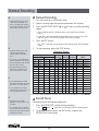
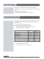
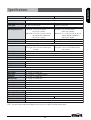
2(SP) 2.67 1/60 60 YES Continuous
6(EP) 8 1/60 60 YES Continuous
18(EP) 24 3/60 20 YES Continuous
24(SP) 32 12/60 5 NO Intermittent
36(SP) 48 18/60 3.3 NO Intermittent
48(SP) 64 24/60 2.5 NO Intermittent
72(SP) 96 36/60 1.6 NO Intermittent
96(SP) 128 48/60 1.2 NO Intermittent
120(SP) 160 1 1 NO Intermittent
168(SP) 224 1.4 0.7 NO Intermittent
240(SP) 320 2 0.5 NO Intermittent
360(SP) 480 3 0.3 NO Intermittent
480(SP) 640 4 0.25 NO Intermittent
720(SP) 960 6 0.16 NO Intermittent
960(SP) 1280 8 0.12 NO Intermittent
Recording Speeds & Duration
Recording
Intervals Sec.
Rec.
Fields/Sec.
Audio
Recording
Tape
Motion
3 HR 4 HR 1/50 50 YES Continuous
12 HR 16 HR 5/50 10 YES Continuous
18 HR 24 HR 7/50 7.1 YES Continuous
24 HR 32 HR 9/50 5.6 YES Continuous
36 HR 48 HR 12/50 4.2 NO Step
48 HR 64 HR 16/50 3.1 NO Step
72 HR 96 HR 24/50 2.1 NO Step
96 HR 128 HR 32/50 1.6 NO Step
120 HR 160 HR 40/50 1.3 NO Step
168 HR 224 HR 1.1 0.9 NO Step
240 HR 320 HR 1.6 0.6 NO Step
360 HR 480 HR 2.4 0.4 NO Step
480 HR 640 HR 3.2 0.3 NO Step
720 HR 960 HR 4.8 0.2 NO Step
960 HR 1280 HR 6.4 0.1 NO
Step
PAL
NTSC
PAL
NTSC
PAL
NTSC
PAL
NTSC
✎ (SP) means to be recorded by SP heads. (EP) means to be recorded by EP heads.
(NTSC)
T-120 E-180
T-160
E-240
NTSC PAL
Normal Recording
La page est en cours de chargement...
La page est en cours de chargement...
La page est en cours de chargement...
La page est en cours de chargement...
La page est en cours de chargement...
La page est en cours de chargement...
La page est en cours de chargement...
La page est en cours de chargement...
La page est en cours de chargement...
La page est en cours de chargement...
La page est en cours de chargement...
La page est en cours de chargement...
La page est en cours de chargement...
La page est en cours de chargement...
La page est en cours de chargement...
La page est en cours de chargement...
La page est en cours de chargement...
La page est en cours de chargement...
La page est en cours de chargement...
La page est en cours de chargement...
La page est en cours de chargement...
La page est en cours de chargement...
La page est en cours de chargement...
La page est en cours de chargement...
La page est en cours de chargement...
La page est en cours de chargement...
La page est en cours de chargement...
La page est en cours de chargement...
La page est en cours de chargement...
La page est en cours de chargement...
La page est en cours de chargement...
La page est en cours de chargement...
La page est en cours de chargement...
La page est en cours de chargement...
La page est en cours de chargement...
La page est en cours de chargement...
La page est en cours de chargement...
La page est en cours de chargement...
La page est en cours de chargement...
La page est en cours de chargement...
La page est en cours de chargement...
La page est en cours de chargement...
La page est en cours de chargement...
La page est en cours de chargement...
La page est en cours de chargement...
La page est en cours de chargement...
La page est en cours de chargement...
La page est en cours de chargement...
La page est en cours de chargement...
La page est en cours de chargement...
La page est en cours de chargement...
La page est en cours de chargement...
La page est en cours de chargement...
La page est en cours de chargement...
La page est en cours de chargement...
La page est en cours de chargement...
La page est en cours de chargement...
La page est en cours de chargement...
La page est en cours de chargement...
La page est en cours de chargement...
La page est en cours de chargement...
La page est en cours de chargement...
La page est en cours de chargement...
La page est en cours de chargement...
La page est en cours de chargement...
La page est en cours de chargement...
La page est en cours de chargement...
La page est en cours de chargement...
La page est en cours de chargement...
La page est en cours de chargement...
La page est en cours de chargement...
La page est en cours de chargement...
La page est en cours de chargement...
La page est en cours de chargement...
La page est en cours de chargement...
La page est en cours de chargement...
La page est en cours de chargement...
La page est en cours de chargement...
La page est en cours de chargement...
La page est en cours de chargement...
La page est en cours de chargement...
La page est en cours de chargement...
La page est en cours de chargement...
La page est en cours de chargement...
La page est en cours de chargement...
La page est en cours de chargement...
La page est en cours de chargement...
La page est en cours de chargement...
La page est en cours de chargement...
La page est en cours de chargement...
La page est en cours de chargement...
La page est en cours de chargement...
La page est en cours de chargement...
La page est en cours de chargement...
La page est en cours de chargement...
La page est en cours de chargement...
La page est en cours de chargement...
La page est en cours de chargement...
La page est en cours de chargement...
La page est en cours de chargement...
La page est en cours de chargement...
La page est en cours de chargement...
La page est en cours de chargement...
La page est en cours de chargement...
La page est en cours de chargement...
La page est en cours de chargement...
La page est en cours de chargement...
La page est en cours de chargement...
La page est en cours de chargement...
La page est en cours de chargement...
La page est en cours de chargement...
La page est en cours de chargement...
La page est en cours de chargement...
La page est en cours de chargement...
La page est en cours de chargement...
La page est en cours de chargement...
-
 1
1
-
 2
2
-
 3
3
-
 4
4
-
 5
5
-
 6
6
-
 7
7
-
 8
8
-
 9
9
-
 10
10
-
 11
11
-
 12
12
-
 13
13
-
 14
14
-
 15
15
-
 16
16
-
 17
17
-
 18
18
-
 19
19
-
 20
20
-
 21
21
-
 22
22
-
 23
23
-
 24
24
-
 25
25
-
 26
26
-
 27
27
-
 28
28
-
 29
29
-
 30
30
-
 31
31
-
 32
32
-
 33
33
-
 34
34
-
 35
35
-
 36
36
-
 37
37
-
 38
38
-
 39
39
-
 40
40
-
 41
41
-
 42
42
-
 43
43
-
 44
44
-
 45
45
-
 46
46
-
 47
47
-
 48
48
-
 49
49
-
 50
50
-
 51
51
-
 52
52
-
 53
53
-
 54
54
-
 55
55
-
 56
56
-
 57
57
-
 58
58
-
 59
59
-
 60
60
-
 61
61
-
 62
62
-
 63
63
-
 64
64
-
 65
65
-
 66
66
-
 67
67
-
 68
68
-
 69
69
-
 70
70
-
 71
71
-
 72
72
-
 73
73
-
 74
74
-
 75
75
-
 76
76
-
 77
77
-
 78
78
-
 79
79
-
 80
80
-
 81
81
-
 82
82
-
 83
83
-
 84
84
-
 85
85
-
 86
86
-
 87
87
-
 88
88
-
 89
89
-
 90
90
-
 91
91
-
 92
92
-
 93
93
-
 94
94
-
 95
95
-
 96
96
-
 97
97
-
 98
98
-
 99
99
-
 100
100
-
 101
101
-
 102
102
-
 103
103
-
 104
104
-
 105
105
-
 106
106
-
 107
107
-
 108
108
-
 109
109
-
 110
110
-
 111
111
-
 112
112
-
 113
113
-
 114
114
-
 115
115
-
 116
116
-
 117
117
-
 118
118
-
 119
119
-
 120
120
-
 121
121
-
 122
122
-
 123
123
-
 124
124
-
 125
125
-
 126
126
-
 127
127
-
 128
128
-
 129
129
-
 130
130
-
 131
131
-
 132
132
-
 133
133
-
 134
134
-
 135
135
-
 136
136


Marmitek TLV9600 Le manuel du propriétaire
- Catégorie
- Lecteurs de cassettes
- Taper
- Le manuel du propriétaire
dans d''autres langues
- English: Marmitek TLV9600 Owner's manual
- Deutsch: Marmitek TLV9600 Bedienungsanleitung
- Nederlands: Marmitek TLV9600 de handleiding
Documents connexes
Autres documents
-
Samsung SVR-960JP Manuel utilisateur
-
Panasonic AG-DTL1 Manuel utilisateur
-
-
-
-
-
-
Aiwa HV-MX1 Le manuel du propriétaire
-
-