GE ZIC303NPPII Guide d'installation
- Catégorie
- Frigos
- Taper
- Guide d'installation

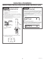
INSTALLATION
INSTRUCTIONS
30” Integrated Bottom Freezer Refrigerator
30” Integrated Bottom Freezer Wine Reserve
ENGLISH/FRANÇAIS/ESPAÑOL.
MONOGRAM.COM

2
31-1000169 Rev. 4
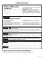
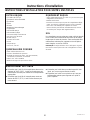
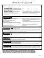
Safety Information
BEFORE YOU BEGIN
Read these instructions completely and carefully.
•
IMPORTANT – Save these instructions for
local inspector’s use. Observe all governing codes and
ordinances.
•
Note to Installer – Be sure to leave these
instructions with the Consumer.
• Note to Consumer – Keep these instructions with
your Owner’s Manual for future reference.
If you received a damaged unit, you should immediately
contact your dealer or builder.
Skill Level – Installation of this unit requires basic
mechanical, carpentry and plumbing skills. Proper
installation is the responsibility of the installer. Product
failure due to improper installation is not covered under
the Monogram Warranty. See the Owner’s Manual for
warranty information.
WARNING
Tip Over Hazard.
These appliances are top heavy, especially with any doors open, and must be secured to prevent tipping
forward which could result in death or serious injury. Read and follow the entire installation instructions for
securing the appliance with the anti-tip system.
WARNING
Explosion Hazard.
Keep flammable materials and vapors, such as gasoline, away from appliance. Failure to do so can result
in fire, explosion, or death.
WARNING
To reduce the risk associated with choking, do not allow children under 3 years of age to
have access to small parts during the installation of this product.
CAUTION
Lifting Hazard
This unit is very heavy. To reduce the risk of person injury during maneuvering and installing this appliance,
2 people are required for proper installation.
CAUTION
.HHSILQJHUVRXWRIWKH³SLQFKSRLQWƎDUHDVFOHDUDQFHVEHWZHHQWKHGRRUVDQGEHWZHHQWKH
doors and cabinet are necessarily small. Be careful closing doors when children are in the area.
WARNING
Electrical Shock Hazard.
Plug into a grounded 3-prong outlet.
Do not remove the ground prong.
Do not use an adapter.
Immediately discontinue use of a damaged supply cord.
If the supply cord is damaged it must be replaced by a
qualified service professional with an authorized service
part from the manufacturer.
Do not use an extension cord with this appliance.
Failure to follow these instructions can result in death,
fire, or electrical shock.
Follow the instructions in the section Grounding the unit.
This appliance must be installed with a means in the
fixed house wiring or circuit breaker for disconnecting the
appliance from the electrical supply after installation.
For Monogram local service in your area, visit monogram.com or call 800.444.1845.
For Monogram service in Canada, visit monogram.ca or call 800.561.3344.
For Monogram Parts and Accessories, visit monogram.com or call 800.444.1845.
For Monogram Parts and Accessories in Canada, visit monogram.ca or call 800.661.1616.

3
31-1000169 Rev. 4
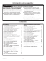
Safety Information
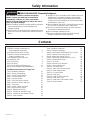
Contents
WARNING
EXPLOSION HAZARD Flammable Refrigerant
This appliance contains isobutane refrigerant,
R600a, a natural gas with high environmental
compatibility. However, it is also combustible.
Adhere to the warnings below to reduce the risk of
injury or property damage.
1) When handling, installing and operating the appliance,
care should be taken to avoid damage to the
refrigerant tubing.
2) Service shall only be performed by authorized service
personnel. Use only manufacturer-authorized service
SDUWVƎ
3) Dispose of unit in accordance with Federal and Local
Regulations. Flammable refrigerant and insulation
material used require special disposal procedures.
Contact your local authorities for the environmentally
safe disposal of your unit.
4) Keep ventilation openings in the appliance enclosures
or in the built-in structure clear of obstruction.
5) Do not use mechanical devices or other means to
accelerate the defrosting process.
6) Do not damage refrigerant circuit.
7) Do not use electrical appliances inside the food
storage compartment of the appliance.
Design Guide
Cabinet Enclosure Dimensions for
Fully Integrated Instructions 4
Unit Dimensions with 3/4” Panels 5
Cabinet Enclosure Dimensions for
Single or Multiple Units 6
The Installation Space (per unit) 7
Grounding the Unit 7
115° Door Swing 8
90° Door Swing 9
SS Panel Accessory & Dimensions 10
ƎFP&XVWRP3DQHO'LPHQVLRQV
Installation Instructions for Single Unit
Tools, Hardware, Materials 12
Step 1. Remove Packaging 13
Step 2. Install Anti-tip Bracket 14
Step 3. Connect Water Line 14
Step 4. Connect Power 14
Step 5. Slide Unit into Enclosure 15
Step 6. Remove Toekick and Vent 15
Step 7. Level Unit 15
Step 8. Install Toekick and Vent 16
Step 9. Reverse Door Swing 16
Step 10. Adjust Door Swing 17
Step 11. Install Door Bracket Covers 17
Step 12. Install Door and Drawer Panels 18
Step 13. Start Icemaker 19
Installation Instructions for Multiple Units
Tools, Hardware, Materials 20
Step 1. Remove Packaging 21
Step 2. Install Heater Unification Kit(S) to Unit 2 22
Step 3. Reverse Door Swing (Unit 1) 24
Step 4. Adjust Door Swing (Unit 1) 26
Step 5. Install Door Bracket Covers (Unit 1) 26
Step 6. Installing Other Units 26
Step 7. Join Units 26
Step 8. Install Anti-Tip Brackets 27
Step 9. Connect Water Line 27
Step 10. Connect Power 27
Step 11. Slide Units into Enclosures 28
Step 12. Install Hinge Guard 28
Step 13. Connect Heater 28
Step 14. Level Units 29
Step 15. Install Toekick And Vent 30
Step 16. Install Front Trim 30
Step 17. Install Door and Drawer Panels 31
Step 18. Start Icemaker 32

4
31-1000169 Rev. 4
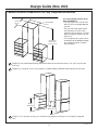
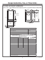
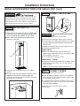
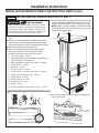
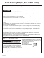
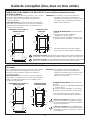
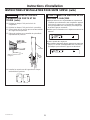
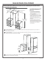
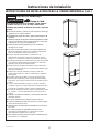
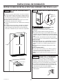
Design Guide (One Unit)
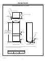
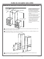
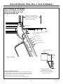
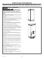
Cabinet Enclosure Dimensions For Fully Integrated Instructions
Height options
80" (203.2 cm)
or *84" (213.4 cm)
30" Finished Width
(76.2 cm)
25" min. depth
(63.5 cm)
7KHFXWRXWGHSWKPXVWEHƎIRU
flush installations.
• The front face of the unit fits flush
ZLWKƎFPGHSWKDGMDFHQW
cabinets.
7KHXQLWFDQILWLQWRDƎ
FPPLQLPXPƎFP
maximum high enclosure. The unit
LWVHOIFDQRQO\EHUDLVHGWRƎ
(204.2 cm).
• The refrigerator door panel can be
FRQVWUXFWHGWRILOODGGLWLRQDOKHLJKW
see Stainless Steel or Custom
Panel sections.
'HVLJQ7LS:HUHFRPPHQGILQLVKLQJWKHLQVLGHVXUIDFHRIWKHHQFORVXUHDPLQRIƎFPIURPWKH
front face.
'HVLJQ7LS,IXVLQJƎFPHQFORVXUHFRQVLGHUDGGLQJDILQLVKHGYDOHQFHDERYHWKHXQLWFDVH
34 3/8"
(87.3 cm)
34 3/8"
(87.3 cm)
Design Tip: It is possible to align your unit drawer with adjacent cabinetry for a completely integrated
look.

5
31-1000169 Rev. 4
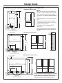
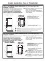
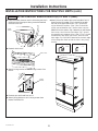
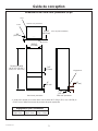
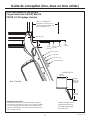
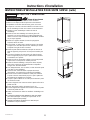
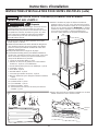
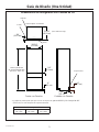
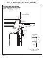
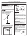
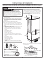
Design Guide
Height adjustable
from
79-3/8” to 80-3/8” *
(201.6 cm - 204.2 cm)
23-3/4"
(60.3 cm)
29-3/4"
(75.6 cm)
1-1/4"
(3.2 cm)
3/4"
(19.1 mm)
1/8"
(3.2 mm)
4"
(10.2 cm)
6"
(15.2 cm)
Case
Door
Panel
Clearance
Front with Panels Side with Panels
8QLW'LPHQVLRQVZLWKƎ3DQHOV
Top with Panels
Install Clearances
Top
ƎPP
Each Side
ƎPP
Rear
ƎPP
7KH8QLWFDQEHDGMXVWHGWRILWLQWRDFDELQHWVSDFHWKDWLVƎFPWRƎ
(214.3 cm) with the appropriate door panel kit.
(Case and Door only)

6
31-1000169 Rev. 4
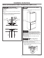
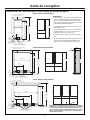
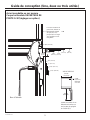
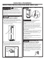
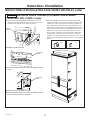
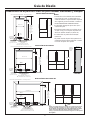
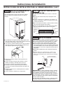
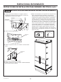
Design Guide
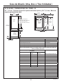
Cabinet Enclosure Dimensions for Single or Multiple Units
77”
(195.5 cm)
Hinge Side
Anti Tip Location - DO NOT
obstruct this area.
Electrical and Water
Area Connection
6” (15.2 cm)
Electrical Outlet and
Home Water Source
1 per product
E = 5” (12.4 cm) x 6” (15.2 cm)
W = 6.25” (15.87 cm) x 6” (15.2 cm)
30” (76.2 cm)
4-3/8”
(11 cm)
25”
(63.5 cm)
Product
Depth
Opening
Height
80”
(203.2 cm)
min.
84”
(213.4 cm)
max.
77”
(195.5 cm)
E
W
ONE PRODUCT INSTALLATION
TWO PRODUCTS INSTALLATION
77”
(195.5 cm)
Hinge Side
Hinge Side
Electrical and Water
Area Connection
6” (15.2 cm)
25”
(63.5 cm)
Product
Depth
Anti Tip Location - DO NOT
obstruct this area.
60” (152.4 cm)
Opening
Height
80”
(203.2 cm)
min.
84”
(213.4 cm)
max.
4-3/8”
(11 cm)
E
W
E
W
34-1/8”
(86.7 cm)
77”
(195.5 cm)
Electrical Outlet and
Home Water Source
1 per product
E = 5” (12.4 cm) x 6” (15.2 cm)
W = 6.25” (15.87 cm) x 6” (15.2 cm)
THREE PRODUCTS INSTALLATION
25”
(63.5 cm)
Product
Depth
Electrical Outlet and Home Water Source
1 per product
E = 5” (12.4 cm) x 6” (15.2 cm)
W = 6.25” (15.87 cm) x 6” (15.2 cm)
90” (228.6 cm)
Anti Tip Location - DO NOT
obstruct this area.
Electrical and Water
Area Connection
6” (15.2 cm)
Opening
Height
80”
(203.2 cm)
min.
84”
(213.4 cm)
max.
77”
(195.5 cm)
4-3/8”
(11 cm)
E
W
E
W
E
W
34-1/8”
(86.7 cm)
64”
(86.7 cm)
Hinge Side
Hinge Side
Hinge Side
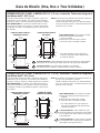
NOTES:
• When two or three units are installed side
by side, an exterior heater must be applied
to the left exterior wall of the second and/
RUWKLUGXQLW6HH([WHULRU+HDWHU8QL¿FDWLRQ
Kit.
• Toekick dimension is 4” (10.2 cm) from the
ÀRRU
•7KHSURGXFWFDQ¿WLQWRD´
cm) minimum and up to 84 1/2” (214.6 cm)
maximum high enclosure.
• The unit can only be raised to 80-3/8”
(204.2 cm).
• The unit door panel can be constructed to
¿OODGGLWLRQDOKHLJKW6HHGRRUDGMXVWPHQW
section.
25
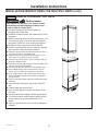
SIDE VIEW
25" (63.5)
3 1/2"
(8.9)
Finished
Return
Back
127(&RQ¿JXUDWLRQVZLWKXQLWVLQVWDOOHGKLQJHWRKDQGOH
will result in interference while opening doors. To enable
all three doors to open independently, additional clearance
between the hinge to handle units is required and the
middle door should be set to a 90 degree opening.

7
31-1000169 Rev. 4
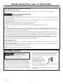
Design Guide (One, Two, or Three Units)
THE INSTALLATION SPACE (Per Unit)
Water and Electrical Locations
Locate electrical and water supply connections in the areas shown on the Cabinet Dimensions section page.
WARNING
Connect to potable water supply only.
PREPARING INSTALL WATER LINE
• A cold water supply is required for automatic icemaker operation. The water pressure must be between 40 and 120
p.s.i. (275-827 kPa).
5RXWHƎFP2'FRSSHURU6PDUW&RQQHFW
™
plastic tubing between the house cold water line and the water
connection location.
• Tubing should be long enough to extend to the front of the enclosure.
• Water line can enter an opening through the floor or back wall.
• Install a shut-off valve between the icemaker water valve and cold water supply in the home.
NOTE:
• It is recommended that the water shut-off valve be placed in a location that is easily accessible. We do not advise
placing it behind the unit because of access difficulties. If it is necessary to install the valve behind the unit, it must
be located in the area shown on Design Guide.
• Saddle type shut-off valves are included in many water supply kits, but are not recommended for this application.
• The only GEA-approved plastic tubing is supplied in the SmartConnect
™
Refrigerator Tubing kits. Do not use any
other plastic water supply line because the line is under pressure at all times. Other types of plastic may crack or
rupture with age and cause water damage to your home. See water line kits on Assessories Page.
• Commonwealth of Massachusetts Plumbing Codes 248CMR shall be adhered to. Saddle valves are illegal and use
is not permitted in Massachusetts. Consult with your licensed plumber.
Electrical Specifications
• A 115-volt, 60-Hz., 15- or 20-amp power supply is required. An individual properly grounded branch circuit or circuit
breaker is recommended.
• Install a properly grounded 3-prong electrical receptacle recessed into the back wall. Electrical must be located on
rear wall as shown in the Cabinet Dimensions section.
NOTE: GFI (ground fault interrupter) is not recommended.
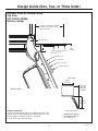
GROUNDING THE UNIT
The power cord of this appliance is equipped with a
3-prong (grounding) plug which mates with a standard
three-prong (grounding) wall receptacle to minimize the
possibility of electric shock hazard from this appliance.
Have the wall outlet and circuit checked by a qualified
electrician to make sure the outlet is properly grounded.
Where a standard 2-prong wall outlet is encountered, it
is your personal responsibility and obligation to have it
replaced with a properly grounded 3-prong wall outlet.
DO NOT, UNDER ANY
CIRCUMSTANCES, CUT
OR REMOVE THE THIRD
(GROUND) PRONG FROM
THE POWER CORD.
DO NOT USE AN ADAPTER PLUG TO CONNECT THE
UNIT TO A 2-PRONG OUTLET.
DO NOT USE AN EXTENSION CORD WITH THIS
APPLIANCE.
WARNING
Electrical Shock
Hazard.
Failure to follow these instructions can
result in death, fire, or electrical shock.

8
31-1000169 Rev. 4
Design Guide (One, Two, or Three Units)
1-1/2" (3.8 cm)
1-1/4" (3.2 cm)
1" (2.5 cm)
3/4" (1.9 cm)
1-1/2"
(3.8 cm)
2-1/16" (5.4 cm)
1-1/4"
(3.2 cm)
1-3/8"
(3.5 cm)
1"
(2.5 cm)
3/4"
(1.9 cm)
1/8" (3.2 mm)
Allow 17" (43.2 cm) minimum
clearance to a wall for a full
115° door swing.
Refrigerator
Stainless Steel or Custom Panels
Top View
115° DOOR SWING
(factory setting)
Product Clearances
These units are equipped with a 2-position door stop. The
factory-set 115° door swing can be adjusted to 90° if clear-
ance to adjacent cabinets or walls is restricted.
For 90° Door swing see next page.
Not to scale
TOP VIEW
DIMENSIONS BASED
ON HANDLE HEIGHT
OF 2-9/16” (6.5)
DOOR OPEN 115°
29 1/4”
(74.3 cm)
29 15/16”
(76.0 cm)
16-9/16"
(42.1 cm)
Minimum
to a Wall

9
31-1000169 Rev. 4
Design Guide (One, Two, or Three Units)
For a 90º door swing
allow 4" (10.2 cm)
min. clearance to a
wall, for stainless
steel models.
1-1/2"
(3.8 cm)
2-1/4"
(5.7 cm)
1-1/4"
(3.2 cm)
1"
(2.5 cm)
3/4"
(1.9 cm)
1-1/2" (3.8 cm)
1-1/4" (3.2 cm)
1-3/16"
(3 cm)
1" (2.5 cm)
3/4" (1.9 cm)
Refrigerator
1/8" (3.2 mm)
Stainless Steel or Custom Panels
Top View
90° DOOR SWING
(optional setting)
Not to scale
TOP VIEW
DOOR OPEN 90°
DIMENSIONS BASED
ON HANDLE HEIGHT
OF 2-9/16” (6.5)
33 1/4”
(84.5 cm)
29 1/4”
(74.3 cm)
5-1/8"
(13.0 cm)
Minimum
to a Wall

10
31-1000169 Rev. 4
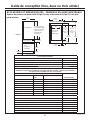
Design Guide (One, Two, or Three Units)
SS PANEL ACCESSORY & DIMENSIONS
ƎFP7KLFN6ROLG'RRU3DQHO2SWLRQVDQGƎFP7KLFN)UDPHIRU*ODVV'RRU
(75.6 cm)
29-3/4"
4" (10.2 cm)
7-9/16"
(19.2 cm)
22-3/4"
(57.8 cm)
1/8" (3.2 mm) Min.*
Fresh
Food
Ice Drawer
Cabinets
Freezer/
Convertible
Drawer
45-3/8" (115.3 cm) for
80" (203.2 cm) Installation
49-3/8" (125.4 cm) for
84" (213.4 cm) Installation
(75.6 cm)
29-3/4"
23"
(58.4 cm)
Glass Panel
for Fresh Food
45-3/8"
(115.3 cm)
49-3/8"
3-3/8"
(8.6 cm)
6"
(15.2 cm)
6"
(15.2 cm)
80"
(203.2 cm)
Install.
10"
(25.4 cm)
84"
(213.4 cm)
Install.
ACCESSORIES/KITS
Kit Name Instruction PN
+HDWHU8QL¿FDWLRQ.LW ZUG30
Water Line 8’ (2.5m) WX08X10006
Water Line 15’ (4.6m) WX08X10015
Water Line 25’ (7.6m) WX08X10025
Stainless Steel Full Door and Drawer Panel Kits (Order for a Full Product)
NOTE: Each kit also contains matching top door, freezer and customizable
drawer panels, and toe kick.
FULL DOOR & DRAWER KIT ATTRIBUTES/REQUIREMENTS
Instructions PNDoor Front Type: Door Height Left or Right
Glass 80” Left ZKGSN809NLH
Glass 80” Right ZKGSN804NRH
Glass 84” Left ZKGSN849NLH
Glass 84” Right ZKGSN844NRH
Solid 80” Left ZKSSN809NLH
Solid 80” Right ZKSSN804NRH
Solid 84” Left ZKSSN849NLH
Solid 84” Right ZKSSN844NRH
Handles and Mountings Instructions PN
Minimalist Handle Full Kit ZKGC3H3CNSS
Minimalist Door Handle WR12X32600
Minimalist Handle (Drawer) WR12X32406
Statement Handle Full Kit ZKGC3H3PNSS
Statement Door Handle WR1232571
Statement Freezer Handle WR12X32599
Custom Panel Handle Stud Kit ZKPN

11
31-1000169 Rev. 4
Design Guide (One, Two, or Three Units)
3/4ƎFP&867203$1(/',0(16,216ƎFP+LJK)XOO\
Integrated Installation
ƎFP&867203$1(/',0(16,216ƎFP+LJK)XOO\
Integrated Installation
If you choose to install custom panels, they must be cut
to the dimensions shown. The panels will attach to the
door and drawers using a hook and bracket system.
EXTREMELY IMPORTANT: Custom wood panels
PXVWEHDWOHDVWƎFPWKLFNZKHUHKRRNVDQG
bracket hardware are attached. Refer to Templates
for hook and bracket location.
NOTE:7KLVSURGXFWLVGHVLJQHGWRKDQGOHƎFP
panels that are made of wood.
Ǝ[Ǝ[FPLVWKHPD[LPXP
opening for a glass window. The opening may be
smaller if desired.
IMPORTANT NOTE: Maximum panel weight:
A Refrigerator Door Panel: 33 lbs.
B Freezer Drawer Panel: 9 lbs.
C Convertible Drawer Panel: 19 lbs.
IMPORTANT NOTE: Maximum panel weight:
A Refrigerator Door Panel: 33 lbs.
B Freezer Drawer Panel: 9 lbs.
C Convertible Drawer Panel: 19 lbs.
29-3/4”
(75.6 cm)
33-3/8”
(84.8 cm)
3-3/8”
(8.6 cm)
6”
(15.2 cm)
6”
(15.2 cm)
3-3/8”
(8.6 cm)
23”
(58.4 cm)
45-3/8”
(115.3 cm)
A
B
C
(115.3 cm)
45-3/8
"
(75.6 cm)
29-3/4"
7-9/16
"
(19.2 cm)
22-3/4
"
(57.8 cm)
(10.7 cm)
4
"
PANELS FOR SOLID DOOR
AND DRAWERS
PANELS FOR SOLID DOOR
AND DRAWERS
PANELS FOR
GLASS DOOR
PANELS FOR
GLASS DOOR
6W\OHVPXVWEHDPLQƎFPWR
cover aluminum door frame.
6W\OHVPXVWEHDPLQƎFPWR
cover aluminum door frame.
Design Tip: Some amount of each panel will be visible on the interior side
of the unit. It is recommended that both sides of each panel be finished.
Design Tip: If using custom panels, a custom toe kick should
be considered. The Bottom of case is white.
Design Tip: Some amount of each panel will
be visible on the interior side of the unit. It is
recommended that both sides of each panel
be finished.
Design Tip: If using custom panels, a custom
toe kick should be considered. The Bottom of
case is white.
29-3/4”
(75.6 cm)
33-3/8”
(84.8 cm)
3-3/8”
(8.6 cm)
10”
(25.4 cm)
6”
(15.2 cm)
3-3/8”
(8.6 cm)
23”
(58.4 cm)
45-3/8”
(115.3 cm)
A
B
C
(115.3 cm)
45-3/8
"
(75.6 cm)
29-3/4"
7-9/16
"
(19.2 cm)
22-3/4
"
(57.8 cm)
(10.7 cm)
4
"

12
31-1000169 Rev. 4
Installation Instructions
INSTALLATION INSTRUCTIONS FOR SINGLE UNIT
TOOLS REQUIRED
Ǝ$OOHQZUHQFK
• Utility knife
• Stepladder
• Bucket
• Level
• Appliance hand truck
• Tubing cutter
ƎRSHQHQGZUHQFK
ƎRSHQHQGZUHQFK
• #2 Phillips screwdriver
• Drill and bit set
ƎVRFNHW
• Safety glasses
• Pliers
ƎUDWFKHW
• Torx T-20, T-30 wrench
HARDWARE SUPPLIED
• Anti-tip bracket & screws
• Panel installation kit
• Door panel templates- Pub # 31-1000149, 31-1000150,
31-1000151, 31-1000152
• Water filter - Part # XWFE
• Drywall Anchors and screws
MATERIALS REQUIRED
ƎFRSSHUZDWHUOLQHWXELQJRU6PDUW&RQQHFW
Refrigerator Tubing kits
• Water shut-off valve
• Custom panels for refrigerator door, freezer drawer and
Convertible drawer
• Velcro w/adhesive if using custom toekick.
FLOORING
For proper installation, this unit must be placed on a level
surface of hard material that is at the same height as the
rest of the flooring. This surface should be strong enough
to support a fully loaded unit, or approximately 1,200 lbs.
NOTE: Protect the finish of the flooring. Cut a large sec-
tion of the cardboard carton and place under the unit
where you are working.
UNIT LOCATION
Ŷ Do not install the unit where the temperature will go
below 60°F (16°C). It will not run often enough to
maintain proper temperatures.
Ŷ Do not install the unit where temperatures will go above
100°F (37°C). It will not perform properly.
Ŷ Do not install the unit in a location exposed to water
(rain, etc.) or direct sunlight.
Ŷ Do not install the unit on a floor not strong enough to
support it fully loaded.

13
31-1000169 Rev. 4
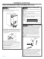
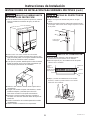
STEP 1 REMOVE PACKAGING
WARNING
Tip Over Hazard.
This appliance is top heavy. Use extreme caution
with moving to prevent tipping over which could
result in death or serious injury.
Ŷ Cut bands and tape on the top and bottom
of packaging with a utility knife.
Ŷ Unfold the cardboard seams and remove the top
of the packaging.
Ŷ Slide the remainder of the box off of the appliance. You
can use a box cutter to cut the remaining cardboard
being VERY CAREFUL not to scratch
the appliance.
Ŷ Remove the EPS supports from around the unit.
Ŷ DO NOT remove the door band or lower EPS banded
parts until unit is ready to go into enclosure.
Ŷ Remove anti-tip bracket and foam blanket from top of
unit and set aside for installation later.
Ŷ Keep front door band and door/drawer tape on unit
until product is installed to anti-tip bracket.
Ŷ Remove trim pieces taped to front of product and set
aside for installation later.
Ŷ Remove all packing tape except for warning labels and
tape with orange warning labels.
Ŷ Pull back, but DO NOT REMOVE, door/drawer tape.
Ŷ Open middle drawer and remove Owner’s Manual
packet which includes unit installation instructions.
Ŷ Close middle drawer and re-apply tape to keep the
door and drawers closed until product is installed to
anti-tip bracket.
Ŷ Cut EPS skid at the sides near the front from the back
of the unit.
Ŷ Push unit forward & remove rear portion of the EPS
skid.
Ŷ Carefully lower rear onto the floor.
Ŷ Lean unit back slightly & remove front portion of the
EPS skid.
Ŷ Discard all unused packaging materials appropriately.
Ŷ The unit can now be moved using an appliance hand
truck or rolled on a properly protected floor by 2
people.
Ŷ Leave any protective film on the unit until installation is
complete.
Installation Instructions
INSTALLATION INSTRUCTIONS FOR SINGLE UNIT

14
31-1000169 Rev. 4
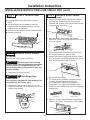
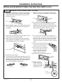
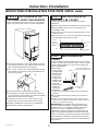
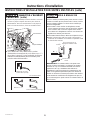
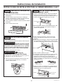
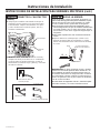
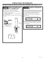
STEP 3 CONNECT WATER LINE
WARNING
Connect to potable water supply
only.
Ŷ Position appliance in front of enclosure.
Ŷ Locate and bring tubing to the front of the cabinet.
Ŷ Turn the water on to flush debris from line. Run about
DTXDUWRIZDWHUWKURXJKWXELQJLQWRDEXFNHWWKHQ
shut off water.
If needed cut the tubing to the proper length so it can
be attached to the water valve.
Copper Tubing:
Ŷ 6OLSDƎQXWDQGIHUUXOHRYHUERWKHQGVRIWKH
copper tubing. Insert tube into the union fitting on the
unit and tighten nut to union.
Ŷ Turn on the water to check for leaks.
SmartConnect™ Tubing:
ŶFollow the instructions provided with the tubing. Over
tightening may cause leaks. Turn on the water to
check for leaks.
NOTE: Coil excess tubing length behind the unit.
Installation Instructions
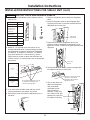
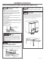
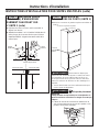
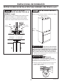
67(3,167$//$17,7,3
BRACKET
Ŷ,QVLGHWRSIDFHRIEUDFNHWVKRXOGEHLQVWDOOHGDWƎ
FP³6ORWƎLQEUDFNHWVKRXOGWREHSODFHGLQ
FHQWHURILQVWDOOVSDFHW\SLFDOO\Ǝ>FP@
Ŷ Mark (within slots, placement) stud and anchor
positions on brackets.
Ŷ Secure bracket using a combination of studs &
anchors.
Ŷ At least 1 stud must be engaged. However, please
engage as many studs as possible within the
enclosure. A minimum of three fasteners should be
used for proper installation.
WARNING
Tip Over Hazard.
These appliances are top heavy, especially with any
doors open, and must be secured to prevent tipping
forward which could result in death or serious injury.
Read and follow the entire installation instructions for
securing the appliance with the anti-tip system.
Water
Line Hole
STEP 4 CONNECT POWER
Ŷ Plug the power cord into the socket.
Ŷ Check to make sure power to unit is on by opening
the ice drawer (FF door will be banded or taped shut)
to see if interior lights are on.
Ŷ The temperature controls are preset at 37°F for the
refrigerator section and 0°F in both the freezer drawer
and customizable drawer.
Ŷ Allow 24 hours to stabilize before making
adjustments.
INSTALLATION INSTRUCTIONS FOR SINGLE UNIT (cont.)
Slot
80”
ƎFP

15
31-1000169 Rev. 4
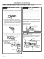
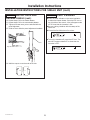
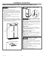
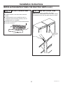
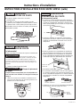
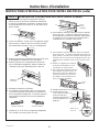
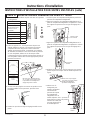
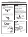
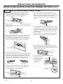
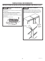
STEP 5 SLIDE UNIT INTO
ENCLOSURE
Roll the unit into the enclosure, being careful not to
pinch the water line or power cord.
Ŷ$ORQJIODWEDURU\DUGVWLFNPD\EHQHHGHGWRJXLGH
the front edge of the anti-tip bracket over the unit.
ŶIf space allows, you may also bend the front edge of
the bracket upward slightly, allowing it to clear the
back of the unit.
ŶRemove top-center trim cover from unit.
ŶSecure the unit to the Anti-tip bracket using both
machine screws & washers to engage the threaded
inserts in the anti-tip bracket.
ŶHand start the screws until unit is in desired location
within the install space.
ŶFinalize unit install by tightening the screws fully.
ŶReinstall Trim cover.
STEP 7 LEVEL UNIT
All models have 4-point leveling. The front is supported
E\OHYHOLQJOHJVWKHUHDULVVXSSRUWHGE\DGMXVWDEOH
wheels. Both are accessible from the front of the unit.
Ŷ7ROHYHOWKHEDFNRIWKHXQLWWXUQWKHƎKH[
nut located above the front wheels. Turn counter
clockwise to raise or clockwise to lower the unit.
Ŷ)RUIURQWOHYHOLQJXVHDƎRSHQHQGZUHQFK
ŶAdjust height of unit to match installation cutout
opening. The unit should be level and plumb with
cabinetry.
NOTICE: The rear leveling wheels and front leveling
OHJVDUHOLPLWHGWRDPD[LPXPKHLJKWDGMXVWPHQWRIƎ
,IWKHLQVWDOODWLRQUHTXLUHVPRUHWKDQƎKHLJKWWKH
installer should elevate the unit on a sheet of plywood
or runners. Cabinetry trim could also be added across
the top of the opening to shorten the opening.
,I\RXDWWHPSWWRUDLVHWKHXQLWPRUHWKDQƎ\RXZLOO
damage the front leveling legs and the rear leveling
wheels.
Installation Instructions
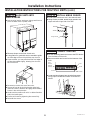
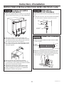
STEP 6 REMOVE TOEKICK AND
VENT
The toekick must be removed to access the leveling
leg system.
ŶRemove band around EPS block in front of toekick.
ŶRemove and dispose of EPS block.
ŶRemove the solid portion of the toekick by pulling
forward.
Ŷ Place the toekick, vent and screws out of the way so
you will have them for reinstallation.
Vent
Screw
Toekick
Vent
Screws
(behind
toekick)
Screw
Up
Leveling Leg
Up
Hex Nut Adjusts
Rear Wheels
INSTALLATION INSTRUCTIONS FOR SINGLE UNIT (cont.)

16
31-1000169 Rev. 4
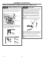
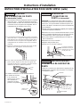
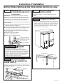
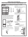
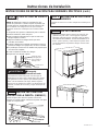
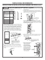
STEP 9 REVERSE DOOR SWING
(if needed) (cont.)
8VLQJDƎ$OOHQZUHQFKUHPRYHWKHVFUHZV
per hinge that secure the door to the unit. Have
someone hold the door while removing these screws
to keep the door from falling.
2SHQWKHKLQJHV8VLQJDƎ$OOHQZUHQFK
remove the 2 screws per hinge that secure the hinge
to the unit cabinet.
5. Remove the trim and hinge pocket from the top of
the unit and install on the opposite sides.
6. Remove the trim and hinge pocket from the bottom
of the refrigerator compartment. Remove the control
panel and gently place in the FZ drawer.
7. Reinstall the control panel.
8. The hinges will be reinstalled in opposite corners.
The hinge from the top will be turned over
and installed at the bottom of the refrigerator
compartment. The hinge from the bottom will be
turned over and installed at the top of the refrigerator
compartment.
9. Install the screws on the refrigerator compartment
cabinet in all 4 places. Screw them in about halfway.
Installation Instructions
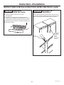
STEP 8 INSTALL TOEKICK AND
VENT
ŶLocate the toekick, vent and screws (removed
earlier).
ŶA custom toekick can be installed to match or
complement the surrounding cabinetry. Use the
supplied toekick as a template.
ŶReinstall the vent using the screws removed earlier.
ŶReinstall the toekick .
Supplied Toekick
Vent Holes
STEP 9 REVERSE DOOR SWING
(if needed)
Skip this step if door swing is satisfactory.
WARNING
Follow all steps when reversing
the door swing. Failure to follow these instructions,
leaving off parts, or overtightening screws, can
lead to the door falling off and result in injury and
property damage.
1. Remove the front tape from unit.
WARNING
Door Hinge Pinch
Point Hazard
This next step is important for safe handling of an
unloaded hinge. Do not skip step 2.
2. Release the hinge springs by using a Torx T-20
wrench to loosen the Torx screw from | to 0 on both
hinges. Close the door.
Top Hinge Bottom Hinge
Slots for
Tabs
Screws
Control Panel
Screws
Screws
INSTALLATION INSTRUCTIONS FOR SINGLE UNIT (cont.)

17
31-1000169 Rev. 4
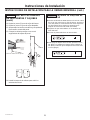
Installation Instructions
Screws
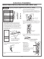
STEP 9 REVERSE DOOR SWING
(cont).
10. To install the top hinge, turn the hinge in the proper
direction—the section of the bracket that will be
attached to the door should be at the bottom of the
hinge. Slide the hinge over the screws and seat the
tabs into the hinge pocket. Tighten the screws.
11. To install the bottom hinge, turn the hinge in the
proper direction—the section of the bracket that will
attach to the door should be at the top of the hinge.
Slide the hinge over the screws and seat the tabs
into the hinge pocket. Tighten the screws. Close the
hinge.
12. Remove the hinge brackets from the door and rein-
stall them on the opposite end, top and bottom.
13. With another person holding the door in place, align
the holes in the door hinge bracket with the holes in
the hinge. Install the screws to the top hinge first.
14. Install screws on the bottom hinge next.
15. Using a Torx T-20
wrench, tighten the
tension on the hinge
springs by turning
the screws from 0
to |.
STEP 10 ADJUST DOOR SWING
(if needed)
NOTE: This unit has a 2-position door stop. When
space does not allow the door to swing to 115°, you
may limit the door swing to a 90°
Skip this step if door opening is satisfactory for your
installation situation.
Ŷ2SHQWKHUHIULJHUDWRUGRRUWRDFFHVVWKHWRSDQG
bottom hinges.
Ŷ/RRVHQWKHERWWRPKLQJHVFUHZVWKDWDWWDFKHGWRWKH
unit
Ŷ3XOOKLQJHIRUZDUGVOLJKWO\LQVHUWKLQJHSLQLQWRWKH
hole nearest the unit.
Ŷ<RXPD\QHHGWRXVHDVPDOOKDPPHUWRIXOO\VHDW
them in place.
Ŷ5HWLJKWHQKLQJHVFUHZV
ŶRepeat for top hinge.
STEP 11 INSTALL DOOR BRACKET
COVERS
Install covers to hide the brackets near the hinges on
the top and bottom of the door. The covers snap in
place.
Door
Screws
Use Torx
T-20 Wrench
Install 1 pin,
per hinge for 90°
door stop.
Hinge screws
Door Bracket
Cover
Hinge
INSTALLATION INSTRUCTIONS FOR SINGLE UNIT (cont.)

18
31-1000169 Rev. 4
Installation Instructions
STEP 12 INSTALL DOOR AND DRAWER PANELS
1. Remove all door and drawer panel hardware and trim
from the unit.
2. Attach A1 - F1 brackets to the door panels in the
locations identified below. Custom panels must have
pre-drilled holes as shown in Door Panel Templates:
31-1000149, 31-1000150, 31-1000151, 31-1000152.
If you purchased an SS Panel Accessory, use the
Phillips machine screws to attach the brackets to the
SS door panels. For custom panels, use an appropriate
wood screw.
3. If you had custom handles made and they are not
currently attached to your panels, do so now.
4. Remove the screw caps from the adjustment pins on
the doors.
5. Open the refrigerator door to attach the refrigerator
panel.
6. Rest the refrigerator panel on the refrigerator door
by aligning the hooks on the panel brackets with the
adjustment pins on the door.
7. Fasten the panel to the refrigerator door in four
locations using the hardware shown below. Do not
tighten the screws. Screws will be tightened after panel
alignment.
8. Shift the panel side to side to ensure even gaps with
the adjacent cabinetry on both sides.
9. Use an allen wrench to
adjust the refrigerator
door panel depth
and height to align
with the adjacent
cabinetry. There must
be a minimum 1/8” gap
between the panel and
the adjacent cabinetry.
Item Quantity
Panel Brackets 12
Phillips Machine
Screws (for use
with SS Panel
Accessory)
34
Allen Hex Socket
Head Screws
12
Washers 12
Door Trim 6
Trim Caps 12
Allen Wrench 2
D1
D1
A1
A1
E1
E1
F1
B1
B1
C1
G1
G1
Refrigerator
Panel
Customizable
Panel
Back View of Panels
Freezer
Panel
Do not tighten the screws, you will
do that after assembly process
and left to right alignment.
Align at top
and bottom
Screw and
Washer
Depth Adjustment
Vertical
Adjustment
Tighten one screw per bracket.
The other screws will be
tightened at the end of the
alignment process.
INSTALLATION INSTRUCTIONS FOR SINGLE UNIT (cont.)

19
31-1000169 Rev. 4
Installation Instructions
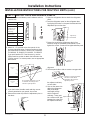
STEP 13 START ICEMAKER
Ŷ Press the zone indicator on the control pad twice
to select the freezer drawer. Press the ICE icon on
the right side of the control. A line will appear under
ICE to show that the icemaker is ON.
Ŷ Be sure nothing interferes with the sweep of the
feeler arm.
Ŷ Discard the first full bucket of ice cubes.
Ŷ To turn the icemaker off, press the ICE icon. The
word OFF appears below ICE to show that the
icemaker is OFF.
STEP 12 INSTALL DOOR AND
DRAWER PANELS
(cont.)
10. Repeat steps 5-9 for the freezer drawer.
11. Repeat steps 5-9 for the customizable drawer.
12. Tighten all screws once you are satisfied with the
panel alignment.
13. Slide on trim to hide the panel adjustment hardware.
14. Add trim caps to cover the ends of the trim.
Trim
R
L
Align trim with bracket
INSTALLATION INSTRUCTIONS FOR SINGLE UNIT (cont.)

20
31-1000169 Rev. 4
Installation Instructions
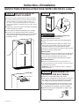
INSTALLATION INSTRUCTIONS FOR MULTIPLE UNITS
TOOLS REQUIRED
Ǝ$OOHQZUHQFK
• Utility knife
• Stepladder
• Bucket
• Level
• Appliance hand truck
• Tubing cutter
ƎRSHQHQGZUHQFK
ƎRSHQHQGZUHQFK
• #2 Phillips screwdriver
• Drill and bit set
ƎVRFNHW
• Safety glasses
• Pliers
ƎUDWFKHW
• Torx T-20, T-30 wrench
HARDWARE SUPPLIED PER UNIT
• Anti-tip bracket & screws
• Panel installation kit
• Door panel templates- Pub # 31-1000149, 31-1000150,
31-1000151, 31-1000152
• Water filter - Part # XWFE
• Drywall Anchors and screws
MATERIALS REQUIRED PER UNIT
ƎFRSSHUZDWHUOLQHWXELQJRU6PDUW&RQQHFW
Refrigerator Tubing kits
• Water shut-off valve
• Custom panels for refrigerator door, freezer drawer and
Convertible drawer
• Velcro w/adhesive if using custom toekick.
• ZUG30 Heater Unification Kit (1 Kit needed for each
additional unit.)
FLOORING
For proper installation, this unit must be placed on a level
surface of hard material that is at the same height as the
rest of the flooring. This surface should be strong enough
to support a fully loaded unit, or approximately 1,200 lbs.
NOTE: Protect the finish of the flooring. Cut a large sec-
tion of the cardboard carton and place under the unit
where you are working.
UNIT LOCATIONS
Ŷ Do not install the units where the temperature will go
below 60°F (16°C). They will not run often enough to
maintain proper temperatures.
Ŷ Do not install the units where temperatures will go
above 100°F (37°C). They will not perform properly.
Ŷ Do not install the units in a location exposed to water
(rain, etc.) or direct sunlight.
Ŷ Do not install units on a floor not strong enough to
support them fully loaded.
La page est en cours de chargement...
La page est en cours de chargement...
La page est en cours de chargement...
La page est en cours de chargement...
La page est en cours de chargement...
La page est en cours de chargement...
La page est en cours de chargement...
La page est en cours de chargement...
La page est en cours de chargement...
La page est en cours de chargement...
La page est en cours de chargement...
La page est en cours de chargement...
La page est en cours de chargement...
La page est en cours de chargement...
La page est en cours de chargement...
La page est en cours de chargement...
La page est en cours de chargement...
La page est en cours de chargement...
La page est en cours de chargement...
La page est en cours de chargement...
La page est en cours de chargement...
La page est en cours de chargement...
La page est en cours de chargement...
La page est en cours de chargement...
La page est en cours de chargement...
La page est en cours de chargement...
La page est en cours de chargement...
La page est en cours de chargement...
La page est en cours de chargement...
La page est en cours de chargement...
La page est en cours de chargement...
La page est en cours de chargement...
La page est en cours de chargement...
La page est en cours de chargement...
La page est en cours de chargement...
La page est en cours de chargement...
La page est en cours de chargement...
La page est en cours de chargement...
La page est en cours de chargement...
La page est en cours de chargement...
La page est en cours de chargement...
La page est en cours de chargement...
La page est en cours de chargement...
La page est en cours de chargement...
La page est en cours de chargement...
La page est en cours de chargement...
La page est en cours de chargement...
La page est en cours de chargement...
La page est en cours de chargement...
La page est en cours de chargement...
La page est en cours de chargement...
La page est en cours de chargement...
La page est en cours de chargement...
La page est en cours de chargement...
La page est en cours de chargement...
La page est en cours de chargement...
La page est en cours de chargement...
La page est en cours de chargement...
La page est en cours de chargement...
La page est en cours de chargement...
La page est en cours de chargement...
La page est en cours de chargement...
La page est en cours de chargement...
La page est en cours de chargement...
La page est en cours de chargement...
La page est en cours de chargement...
La page est en cours de chargement...
La page est en cours de chargement...
La page est en cours de chargement...
La page est en cours de chargement...
La page est en cours de chargement...
La page est en cours de chargement...
La page est en cours de chargement...
La page est en cours de chargement...
La page est en cours de chargement...
La page est en cours de chargement...
La page est en cours de chargement...
La page est en cours de chargement...
La page est en cours de chargement...
La page est en cours de chargement...
La page est en cours de chargement...
La page est en cours de chargement...
La page est en cours de chargement...
La page est en cours de chargement...
-
 1
1
-
 2
2
-
 3
3
-
 4
4
-
 5
5
-
 6
6
-
 7
7
-
 8
8
-
 9
9
-
 10
10
-
 11
11
-
 12
12
-
 13
13
-
 14
14
-
 15
15
-
 16
16
-
 17
17
-
 18
18
-
 19
19
-
 20
20
-
 21
21
-
 22
22
-
 23
23
-
 24
24
-
 25
25
-
 26
26
-
 27
27
-
 28
28
-
 29
29
-
 30
30
-
 31
31
-
 32
32
-
 33
33
-
 34
34
-
 35
35
-
 36
36
-
 37
37
-
 38
38
-
 39
39
-
 40
40
-
 41
41
-
 42
42
-
 43
43
-
 44
44
-
 45
45
-
 46
46
-
 47
47
-
 48
48
-
 49
49
-
 50
50
-
 51
51
-
 52
52
-
 53
53
-
 54
54
-
 55
55
-
 56
56
-
 57
57
-
 58
58
-
 59
59
-
 60
60
-
 61
61
-
 62
62
-
 63
63
-
 64
64
-
 65
65
-
 66
66
-
 67
67
-
 68
68
-
 69
69
-
 70
70
-
 71
71
-
 72
72
-
 73
73
-
 74
74
-
 75
75
-
 76
76
-
 77
77
-
 78
78
-
 79
79
-
 80
80
-
 81
81
-
 82
82
-
 83
83
-
 84
84
-
 85
85
-
 86
86
-
 87
87
-
 88
88
-
 89
89
-
 90
90
-
 91
91
-
 92
92
-
 93
93
-
 94
94
-
 95
95
-
 96
96
-
 97
97
-
 98
98
-
 99
99
-
 100
100
-
 101
101
-
 102
102
-
 103
103
-
 104
104


GE ZIC303NPPII Guide d'installation
- Catégorie
- Frigos
- Taper
- Guide d'installation
dans d''autres langues
- English: GE ZIC303NPPII Installation guide
- español: GE ZIC303NPPII Guía de instalación
Documents connexes
-
GE ZKDP240 Guide d'installation
-
GE ZIC30GNNII Guide d'installation
-
GE ZIC30GNNII Guide d'installation
-
-
-
GE ZIF301NPNII Guide d'installation
-
GE ZDBR240NBS Guide d'installation
-
-
Yes ZIR300NPKII Guide d'installation
-
GE ZIK30GNHII Guide d'installation
Autres documents
-
-
Monogram ZK3SN369VLH Manuel utilisateur
-
Monogram ZKMV Manuel utilisateur
-
 Yardistry YP21015 Mode d'emploi
-
-
 GE Monogram ZDBI240HII Guide d'installation
-
Best AGPCC34W Guide d'installation
-
-
Monogram ZDBR240NBS Guide d'installation
-
Rev-A-Shelf 2 x RAS-FD-KIT Mode d'emploi

