MINI-THERM JV
Section 3D-3 Vent Termination (JVH only)
The sidewall vent terminal and thimble are a part of
the vent system and must be selected from the chosen
vent system Model numbers listed with the other vent
system component parts in Section 3D-2. It provides
a means of installing vent pipe through the building
wall and must be located in accordance with ANSI
Z223.1/NFPA 54, or in Canada CAN/CGA-B149 and
applicable local codes (See Figure 6).
The location of the vent terminal should be chosen so
that exiting ue products don’t come in contact with
nearby shrubbery. In accordance with ANSI Z223.1/
NFPA 54, or CAN/CGA-B149, the terminal must
be located 12” above grade or the anticipated snow
level in areas where snow is expected. Follow any
additional local codes when choosing the location.
3E. Common Venting System
When an existing boiler is removed from a common
venting system, the common venting system is likely
to be too large for proper venting of the appliances
remaining connected to it.
At the time of removal of an existing boiler, the
following steps shall be followed with each appliance
remaining connected to the common venting system
placed in operation, while the other appliances
remaining connected to the common venting system
are not in operation.
1. Seal any unused openings in the common venting
system.
2. Visually inspect the venting system for proper
size and horizontal pitch and determine there is
no blockage or restriction, leakage, corrosion or
other deciencies which could cause an unsafe
condition.
3. Insofar as it is practical, close all building doors
and windows and all doors between the space in
which the appliances remaining connected to the
common venting system are located and other
spaces of the building. Turn on clothes dryers
and any gas burning appliance not connected
to the common venting system. Turn bathroom
exhausts, so they will operate at maximum speed.
Do not operate a summer exhaust fan. Close
replace dampers.
4. Place in operation the appliance being
inspected. Follow the lighting instructions.
Adjust thermostat so appliance will operate
continuously.
5. Test for spillage at the burner opening after ve
minutes of main burner operation.
6. After it has been determined that each appliance
remaining connected to the common venting
system properly vents when tested as outlined
above, return doors, windows, exhaust fans,
replace dampers and any other gas burning
appliance to their previous conditions of use.
7. Any improper operation of the common venting
system should be corrected so the installation
conforms with the National Fuel Gas Code,
ANSI Z223.1. When re-sizing any portion
of the common venting system, the common
venting system should be re-sized to approach
the minimum size as determined using the
appropriate tables in Appendix G in the National
Fuel Gas Code, ANSI Z223.1/NFPA 54.
ALLOWABLE SINGLE WALL STAINLESS STEEL VENT SUPPLIERS AND PART NUMBERS
Example Components
Safe-
Boiler Adapter 5x01BOI FSAAUx
FSBSx
5X00CI FSRCx 2SVSRCxx
Inlet Air Termination FSAIHXX*
FSA--
FSAAUx-
*4", 6" & 7" only **up to 6"
225
152
4
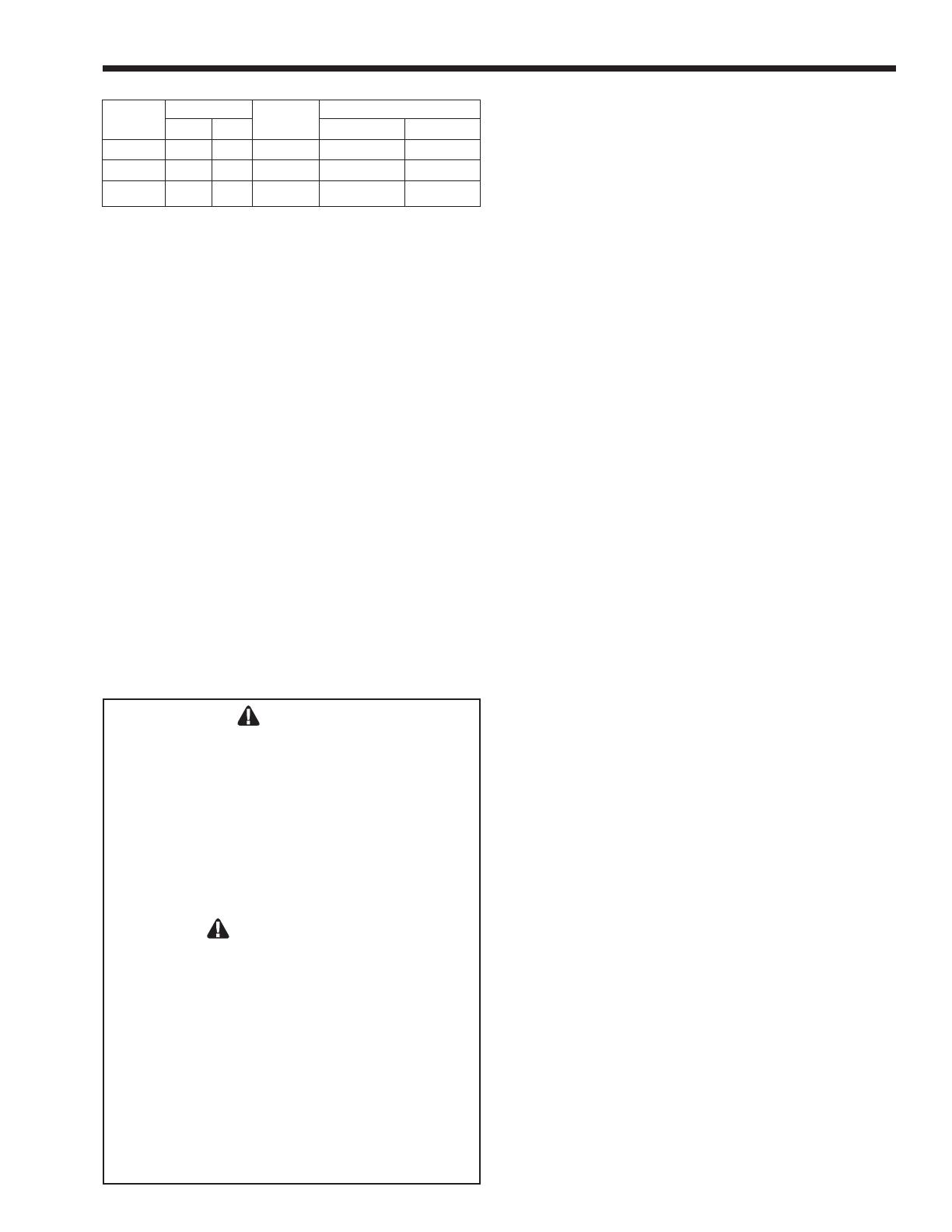
Horizontal Venting Configuration
Table 2. Horizontal Venting Conguration
WARNING
appliances connected to a common vent cannot
gasses into living spaces, common venting should
not be applied, and appliances should each be
AVERTISSEMENT
dispersion des gaz toxiques dans les espaces


