Broan PPG2GI Manuel utilisateur
- Catégorie
- Cheminées
- Taper
- Manuel utilisateur
Ce manuel convient également à

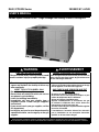
Variable Speed, Inverter Driven - Single Package Gas Heating / Electric Cooling Unit
R6GI / PPG2GI Series 20 SEER / 81% AFUE
USER’S MANUAL
WARNING AVERTISSEMENT
FIRE OR EXPLOSION HAZARD
Failure to follow safety warnings exactly could
result in serious injury or property damage.
RISQUE D’INCENDIE OU D’EXPLOSION
Si les consignes de sécurité ne sont pas suivies à la
lettre, cela peut entraîner la mort, de graves blessures
ou des dommages matériels.
– Do not store or use gasoline or other flammable
vapors and liquids in the vicinity of this or any
other appliance.
WHAT TO DO IF YOU SMELL GAS
• Do not try to light any appliance.
• Do not touch any electrical switch; do not use
any phone in your building.
• Leave the building immediately.
• Immediately call your gas supplier from a
neighbors phone. Follow the gas suppliers
instructions.
• If you cannot reach your gas supplier, call the
fire department.
– Installation and service must be performed by
a qualified installer, service agency or the gas
supplier.
– Ne pas entreposer ni utiliser de l’essence ni d’autres
vapeurs ou liquides inflammables dans le voisinage
de cet appareil, ni de tout autre appareil.
QUE FAIRE SI UNE ODEUR DE GAZ EST
DÉTECTÉE
• Ne mettre en marche aucun appareil.
• Ne toucher aucun interrupteur électrique; ne pas
utiliser de téléphone dans le bâtiment.
• Quitter le bâtiment immédiatement.
• Appeler immédiatement le fournisseur de gaz
en utilisant le téléphone d’un voisin. Suivre les
instructions du fournisseur de gaz.
• Si le fournisseur de gaz n’est pas accessible, appeler
le service d’incendie.
– L’installation et l’entretien doivent être effectués
par un installateur ou une entreprise d’entretien
qualifié, ou le fournisseur de gaz.
DO NOT DESTROY THIS MANUAL. READ ALL INSTRUCTIONS IN THIS MANUAL AND KEEP IN A SAFE PLACE FOR FUTURE REFERENCE.
NE PAS DÉTRUIRE. LIRE TOUTES LES INSTRUCTIONS DONNÉE DANS LE MANUEL ET CONSERVER EN UN LIEU SÛR POUR RÉFÉRENCE ULTÉRIEURE.

2
IMPORTANT SAFETY INFORMATION
Please read all information in this manual thoroughly
and become familiar with the capabilities and use of your
appliance before attempting to operate or maintain this
unit. Pay attention to all safety warnings and any other
special notes highlighted in the manual.
Safety markings are used frequently throughout this
manual to designate a degree or level of seriousness and
should not be ignored. WARNING indicates a potentially
hazardous situation that if not avoided, could result in
personal injury or death. CAUTION indicates a potentially
hazardous situation that if not avoided, may result in minor
or moderate injury or property damage.
WARNING:
To avoid possible equipment damage, fire, or
personal injury, the following instructions must
be observed regarding unit maintenance and
operational procedures.
• Under no circumstances should the appliance owner
attempt to install and/or service this equipment. Some
local codes require licensed installation / service
personnel for this type of equipment. Improper service,
adjustment, or maintenance may cause explosion, fire,
electrical shock or other hazardous conditions which
may result in personal injury or property damage.
• Keep this literature where you have easy access to it in
the future. If a problem occurs, check the instructions
and follow recommendations given. If these suggestions
don’t eliminate your problem, call your servicing
contractor. Do not attempt to service this unit yourself!
• To achieve optimum performance and minimize
equipment failure, it is recommended that periodic
maintenance be performed on this unit. The ability
to properly perform maintenance on this equipment
requires certain mechanical skills and tools. Please
consult your dealer for maintenance information and
availability of maintenance contracts.
• The area around the gas heating / electric cooling unit
and the vicinity of any other gas appliances must be
kept clear and free of combustible materials, gasoline,
and other flammable vapors and liquids. Do not store or
use flammable items such as paint, varnish, or strippers
in the vicinity of the unit.
• For areas around the units gas heating section,
precautions should be taken to prevent blockage of
the flue exhaust and combustion air louvers from large
amounts accumulating snow.
• Do not use the area around the unit as a storage area.
This area must be kept clean and clear of loose or
exposed insulation materials. Examine the unit’s area
when it is installed or when insulation is added, since
some insulation materials may be combustible.
• Do not use this furnace if any part has been under
water. A flood-damaged furnace is extremely dangerous.
Attempts to use the furnace can result in fire or explosion.
A qualified service agency should be contacted to
inspect the furnace and to replace all gas controls,
control system parts, electrical parts that have been
wet or the furnace if deemed necessary.
• Ne pas utiliser cet appareil de chauffage s’il a été en
partie immergé dans l’eau. Un appareil de chauffage
endommagé par une inondation est extrêmement
dangereux. S’il est utilisé, un incendie ou une explosion
peut se produire. Il faut avoir recours à une entreprise
d’entretien qualifiée pour faire inspecter l’appareil de
chauffage et remplacer toutes les commandes de gaz,
les pièces du système de contrôle, les pièces électriques
qui sont entrées en contact avec l’eau ou l’appareil de
chauffage lui-même, si cela est jugé nécessaire.
• Familiarize yourself with the controls that shut off the
gas and electrical power to the unit. If the unit is to be
shut down for an extended period of time, turn off both
the gas and electrical power. For your safety always turn
off both the gas and electrical power before performing
service or maintenance on the furnace. If the gas supply
to the unit must be shut off, refer to the gas valve label
(Figure 2, page 5).
Combustion Air Supply
WARNING:
Combustion air must not be drawn from a corrosive
atmosphere.
The gas heating/electric cooling unit needs an adequate
supply of combustion and ventilation air for proper and
safe operation. Do not block or obstruct air openings on
the unit or air openings supplying the area where it is
installed.
If the unit is operated with inadequate combustion air
supply, the flame roll-out control switch located above
the burners will open, turning off the gas supply to the
burners. The flame roll-out control is a manual reset
device. Do not attempt to reset this device yourself! Call
your servicing contractor.
To maximize heat exchanger life, the combustion air
must be free of chemicals which form corrosive acidic
compounds in the combustion gases.
IMPORTANT NOTE: Do not store any chemicals with
flammable or caustic vapors near the vent termination.
Some examples of these chemicals are:
• Gasoline/Kerosene
• Permanent wave solutions
• Chlorinated waxes and cleaners
• Chlorine based swimming pool chemicals
• Water softening chemicals
• De-icing salts or chemicals
• Carbon tetrachloride
• Halogen type refrigerants
• Cleaning solvents
• Cements, glues, paint removers, varnishes, etc.
• Hydrochloric acid
• Masonry acid washing materials

3
• Whether first or second stage operation is called for by
the thermostat which MUST be two stage capable.
• The outdoor ambient temperature.
• The length of time, unit has been operating during
current cycle.
• The operating speed history for both the current and
the previous operatin cycles.
• EXAMPLE: With a first stage call, if the setpoint was
satisified quickly, the unit will restart the next time at
a lower speed. At a low or intermediate speed, if the
setpoint is not satisfied within 60 minutes, the speed
will be increased. If the unit cycles off after having a
speed increase, the complete next cycle will be at a
higher speed. Also, for first startup and between cycles
there will always be a 5 minute minimum off time (start
delay) imposed.
NOTES:
If first stage cooling does not satisfy the thermostat
demand, then second stage cooling will energize. The
compressor, outdoor fan, and indoor blower will ramp
up to a higher speed.
If the temperature level is re-adjusted, or the system
mode is reset, the outdoor fan, indoor blower, and
compressor will not start immediately. There is
a protective timer circuit in the unit control which
holds the compressor and the outdoor fan off for
approximately 5 minutes following a previous operation
or the interruption of the main electrical power.
Heating Operation (2 Stage Operation)
WARNING:
Should the gas supply fail to shut off or if overheating
occurs, shut off the gas valve to the furnace before
shutting off the electrical supply.
AVERTISSEMENT:
En cas de température excessive, ou s’il est
impossible de couper l’alimentation en gaz,
fermer le robinet manuel d’alimentation en gaz
du générateur d’air chaud avant de couper
l’alimentation électrique.
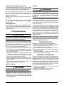
1. Set the thermostat system mode to Heat and the
thermostat fan mode to AUTO. See Figure 1.
2. Set the thermostat temperature selector to the desired
temperature level. The indoor blower and gas heat
module will cycle on and off to maintain the indoor
temperature at the desired heating level.
If first stage heat does not satisfy the thermostat
demand, second stage heat will energize. The indoor
blower motor and inducer motor will ramp to high
speed.
Ductwork
WARNING:
Failure to prevent products of combustion from
being circulated into the occupied space can create
potentially hazardous conditions including carbon
monoxide poisoning that could result in personal
injury or death.
The duct connections must be physically sound and sealed
to the unit’s casing to prevent products of combustion
from entering the occupied space.
The return air and circulating air ductwork must not be
connected to any other heat producing device such as
a fireplace insert, stove, etc. Doing so may result in fire,
explosion, personal injury, carbon monoxide poisoning,
or property damage.
ABOUT THE GAS HEATING / ELECTRIC
COOLING UNIT
This gas heating unit with electric cooling has been
designed and built to provide many years of safe and
dependable comfort, providing it is properly installed
and maintained. With regular maintenance, this unit will
operate satisfactorily year after year. Abuse, improper
use, and/or improper maintenance can shorten the life
of the appliance and create unsafe hazards. A regular
service and maintenance schedule should be established
to ensure efficient and safe operation of the unit. See
System Maintenance on page 5
OPERATING INSTRUCTIONS
Thermostat styles vary. Some models may not include an
auto heat/cool changeover mode and others will have the
auto heat/cool changeover in addition to HEAT & COOL.
Please refer to the thermostat’s User manual for detailed
programming instructions.
A two-Stage cooling/heating thermostat is required to
obtain optimal intended performance.
The thermostat should be mounted about 5 feet above the
floor on an inside wall and not on an outside wall or other
location where its operation may be adversely affected by
radiant heat from fireplaces, sunlight, or lighting fixtures,
and convective heat from warm air registers or electrical
appliances.
Cooling Operation (2 Stage Operation)
1. Set the thermostat system mode to COOL and the
thermostat fan mode to AUTO. See Figure 1.
2. Set the thermostat temperature selector to the desired
temperature level. The outdoor fan, compressor, and
indoor blower will all cycle on and off to maintain the
indoor temperature at the desired cooling level.
3. The unit will operate at 1 of 5 available speeds
predetermined for a balance of optimum capacity and
efficiency. These speeds depend on several factors
including:

4
MAINTENANCE ITEM
FREQUENCY OF MAINTENANCE
BEGINNING
OF HEATING
SEASON
END OF
HEATING
SEASON
MONTHLY
Verify area around the unit is free of combustible materials
X X
Verify combustion and ventilation air is not restricted
X X X
Verify no signs of physical deterioration of the furnace
X X X
Inspect unit support
X X
Inspect return air connections
X X
Clean or replace filter(s)
X
Table 1. Maintenance Schedule
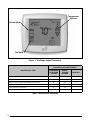
Figure 1. Two-Stage Digital Thermostat
Fan Mode
Temperature
Selector
System Mode

5
Air Filter
WARNING:
Never operate the unit without a filter in the return
air system. Dust and lint in the return air can build
up on the internal components, resulting in loss
of efficiency, equipment damage, and possible
fire risk.
This unit is not supplied with air filter(s) and has no means
for accommodating internal air filter(s). The installer is
responsible for installing a filtration system into the return
air duct of this system. The filter(s) of this system should
be checked monthly.
It is very important to replace or clean the filter(s) installed
in the return air duct of this system. A clogged filter could
cause airflow related problems and reduce the overall
efficiency of your unit. Depending upon which type of filter
was installed with your unit, clean (permanent) or replace
(disposable) filter(s) of your system at the beginning of
every heating season, the beginning of every cooling
season, and when an accumulation of dust and dirt are
visible on the filter.
IMPORTANT: Replace disposable filter(s) installed in
your system only with the same size dimensional filters
that are being replaced. Clean permanent filter(s) as
described by the manufacturer.
TROUBLESHOOTING
Before you call a Technician, check the following:
• Check the thermostat setting. Make sure the system
mode and temperature settings are correct.
• Check the electrical panel for tripped circuit breakers.
• Check the filters for dust accumulation.
• Check the unit and make sure it is clean and not covered
with grass or leaves.
• If the items above don’t resolve your problems, then
call your nearest service technician.
WARRANTY INFORMATION
A warranty certificate with full details is included with the
equipment. Carefully review these responsibilities with
your dealer or service company. The manufacturer will not
be responsible for any costs found necessary to correct
problems due to improper setup, improper installation,
adjustments, improper operating procedure on the part of
the user. Some specific examples of service calls which
are not included in the limited warranty are:
• Correcting wiring problems in the electrical circuit
supplying the equipment.
• Resetting circuit breakers or other switches.
• Adjusting or calibrating of thermostat.
Continuous Indoor Blower Operation
The continuous indoor blower operation is typically used to
circulate the indoor air to equalize a temperature imbalance
due to a solar load, cooking, or fireplace operation.
Set the thermostat fan mode from AUTO to ON (see
Figure 1). The indoor blower will start immediately and
will run continually at 50% of nominal CFM until the fan
switch is reset to AUTO.
NOTE: On some thermostat models the setting may be
called CONT.
The continuous indoor blower operation can be obtained
with the thermostat system switch set in any position,
including OFF.
System Shutdown
Set the thermostat system mode to OFF (see Figure 1)
and the thermostat fan mode to AUTO. NOTE: The system
will not operate, regardless of the thermostat temperature
selector’s setting.
SYSTEM MAINTENANCE
CAUTION:
Verify all electrical power to the unit is disconnected
and the gas is shut off before performing the
following recommended maintenance.
Proper maintenance is most important to achieve the best
performance from the appliance and should be performed
by a qualified service technician at least once a year.
Follow the maintenance schedule and the instructions
below for years of safe, trouble free operation.
• Annually inspect the physical support of the unit to ensure
that it is physically sound without sagging, cracks, gaps,
etc., around the base so as to provide a seal between
the support and the base.
• Annually inspect the return-air connection to ensure that
it is physically sound and is still sealed to the casing
of the unit. Also inspect the unit, ductwork, and vent
system for signs of physical deterioration.
• Do not operate the unit without all doors and covers
in place. Avoid operating the unit when windows and
doors are open.
• Refer to the Maintenance Schedule in Table 1 for
recommended maintenance information.
Regular Cleaning
CAUTION:
DO NOT make contact with any of the internal
electrical components while cleaning the unit.
• Remove any leaves and grass clippings from the
outdoor coil. Check for and remove any obstructions
such as twigs, sticks, etc. Be careful not to damage
the aluminum fins

6
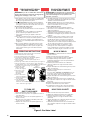
Figure 2. Gas Valve Label
A. This appliance does not have a pilot. It is equipped with
an ignition device which automatically lights the burner.
Do not try to light the burner by hand.
B. BEFORE OPERATING smell all around the appliance
area for gas. Be sure to smell next to the fl oor because
some gas is heavier than air and will settle on the fl oor.
WHAT TO DO IF YOU SMELL GAS
• Do not try to light any appliance.
• Do not touch any electrical switch; do not use any phone
in your building.
• Immediately call your gas supplier from a neighbor’s
phone. Follow the gas supplier’s instructions.
• If you cannot reach your gas supplier, call the fi re
department.
C. Use only your hand to push in or turn the gas control
knob. Never use tools. If the knob will not push in or move
by hand, do not try to repair it, call a qualifi ed service
technician. Force or attempted repair may result in a fi re
or explosion.
D. Do not use this appliance if any part has been under
water. Immediately call a qualifi ed service technician
to inspect the appliance and to replace any part of the
control system and any gas control which has been
under water.
1. ATTENTION! Lire d’abord la liste des mesures de
sécurité ci-dessus.
2. Mettre le thermostat à la position minimale.
3. Couper le courant électrique qui mène à l’appareil.
4. Cet appareil ménager étant doté d’un système
d’allumage automatique, ne pas essayer d’allumer le
brûleur manuellement.
5. Retirer le panneau/volet d’accès de commande
(panneau supérieur s’il s’agit d’un modèle à deux
panneaux).
6. Réglez l’interrupteur de commande du gaz à la position
“OFF”. (voir Figure 1).
7. Attendre cinq (5) minutes pour s’assurer de la
dissipation du gaz.
En cas d’odeur, ARRÊTER LE PROCÉDÉ. Suivre les
instructions ci-dessus (Section B). En l’absence de
toute odeur de gaz, avancer à l’étape suivante.
8. Réglez l’interrupteur de commande du gaz à la position
“ON”. (voir Figure 1).
9. Remettre le panneau/volet d’accès de commande en
place (panneau supérieur s’il s’agit d’un modèle à deux
panneaux).
10. Rebrancher l’appareil sur le réseau électrique.
11. Ajuster le thermostat à la position désirée.
12. Si l’appareil ne fonctionne pas, suivre les “Directives
d’arrêt” cidessous et appeler le technicien de service.
A. Cet appareil ménager n’a pas de veilleuse. II est doté
d’un système d’allumage automatique. Ne pas essayer
d’allumer le brûleur manuellement.
B. AVANT L’USAGE. Attention à une possible odeur de
gaz surtout au niveau du plancher où les gaz les plus
lourds ont la tendance de se concentrer.
EN CAS D’ODEUR DE GAZ.
• Ne mettre en marche aucun appareil électrique.
• Ne toucher à aucun commutateur électrique, ne pas
employer le téléphone.
• Quitter le bâtiment immédiatement et avertir la
compagnie du gaz en utili sant le téléphone d’un voisin.
• A défaut de la compagnie du gaz, avertir le service des
pompiers.
C. Enfoncer ou faire tourner le robinet à gaz à la main
seulement. Ne jamais utiliser d’outils. S’il n’est pas
possible de faire tourner ou d’enfoncer le robinet à la
main, ne pas essayer de le réparer. Faire appel à un
spécialiste. Forcer ou tenter de réparer le robinet pourrait
être à l’origine d’une explosion ou d’un incendie.
D. II est déconseillé d’utiliser cet appareil en contact
prolongé avec l’eau. Faire inspecter ou remplacer
toute commande par un technicien qualifi é si un des
systèmes de contrôle du gaz s’est trouvé sous l’eau.
1. STOP! Read the safety information above on this label.
2. Set the thermostat to the lowest setting.
3. Turn off all electrical power to the appliance.
4. The appliance’s ignition device automatically lights the
burner. Do not try to light burner by hand.
5. Remove the control access door/panel (upper door if
two-door model).
6. Move the gas control switch to the “OFF” position. (See Figure 1)
7. Wait fi ve (5) minutes to clear out any gas. Then smell for gas,
including near the fl oor. If you smell gas, STOP! Follow “B” in above
information. If you don’t smell gas, go to the next step.
8. Move the gas control
switch to the “ON”
position. (See Figure 1)
9. Replace the control
access door/panel
(upper door if two
door model).
10. Turn on all electrical
power to the appliance.
11. Turn the thermostat to a
desired setting.
12. If the appliance will not
operate, follow the
instructions “To Turn Off Gas To Appliance” and call your
service technician or gas supplier.
10186330 (Replaces 7106740)
(10/17)
1. Mettre le thermostat à la position minimale.
2. Débrancher l’appareil en prévision de la réparation.
3. Retirer le panneau/volet d’accès de commande
(panneau supérieur s’il s’agit d’un modèle à deux
panneaux).
4. Réglez l’interrupteur de commande du gaz à la position
“OFF”. Ne forcez pas. (voir Figure 1).
5. Remettre le panneau/volet d’accès de commande en
place (panneau supérieur s’il s’agit d’un modèle à deux
panneaux).
POUR VOTRE SÉCURITÉ.
À LIRE AVANT L’EMPLOI
FOR YOUR SAFETY READ
BEFORE OPERATING
1. Set the thermostat to the lowest setting.
2. Turn off all electrical power to the appliance if service is
to be performed.
3. Remove the control access door/panel (upper door if
two-door model).
4. Move the gas control switch to the “OFF” position. Do
not use force. (See Figure 1)
5. Replace the control access door/panel (upper door if
two-door model).
ATTENTION!
L’inobservation de ces instructions
peut entraîner un incendie ou une explosion pouvant
causer des dam mages à votre propriété à votre
personne, ou la mort.
WARNING:
If you do not follow these instructions
exactly, a fi re or explosion may result causing property
damage, personal injury, or loss of life.
TO TURN OFF
GAS TO APPLIANCE
DIRECTIVES D’ARRÊT
MODE D’EMPLOI
OPERATING INSTRUCTIONS
SWITCH
(L’INTERRUPTEUR )

7

Specifications & illustrations subject to change without notice or incurring obligations (09/18).
O’Fallon, MO, © Nortek Global HVAC LLC 2018. All Rights Reserved.
10239630
(Replaces 709224B)
-
 1
1
-
 2
2
-
 3
3
-
 4
4
-
 5
5
-
 6
6
-
 7
7
-
 8
8


Broan PPG2GI Manuel utilisateur
- Catégorie
- Cheminées
- Taper
- Manuel utilisateur
- Ce manuel convient également à
dans d''autres langues
- English: Broan PPG2GI User manual