Crosley CDEC400FW1 Guide d'installation
- Catégorie
- Sèche-linge électriques
- Taper
- Guide d'installation
Ce manuel convient également à

I
I
stallati
structi
Instructio
'instal "
www.frigidaire.com P/N 134940500A (0710)

CONTENTS
Pre-lnstallation Requirements .......................................................................................................................................... 2
Electrical Requirements .................................................................................................................................................. 3
Exhaust System Requirements ...................................................................................................................................... 3-4
Gas Supply Requirements ............................................................................................................................................ 4-5
Location of Your Dryer.................................................................................................................................................... 5
Rough-In Dimensions ..................................................................................................................................................... 6
Mobile Home Installation ............................................................................................................................................... 7
Unpacking ................................................................................................................................................................... 7
Reversing Door Swing ................................................................................................................................................. 7-9
Electrical Installation .................................................................................................................................................... 10
Grounding Requirements .............................................................................................................................................. 10
Electrical Connections--3-wire ....................................................................................................................................... 11
Electrical Connections--4-wire ........................................................................................................................................ 11
Gas Connection ............................................................................................................................................................ 12
General Installation ....................................................................................................................................................... 12
Replacement Parts........................................................................................................................................................ 12
Fran_ais .................................................................................................................................. 13-24
SAFETY INSTRUCTIONS
Clothes dryer installation and service must be performed by a qualified installer, service agency or the gas supplier.
install the clothes dryer according to the manufacturer's instructions and local codes.
Before beginning installation, carefully read these instructions. This will simplify the installation and ensure the
dryer is installed correctly and safely. Leave these instructions near the Dryer after installation for future reference.
NOTE: The electrical service to the Dryer must conform with local codes and ordinances and the latest edition of the National
Electrical Code, ANSl/NFPA 70, or in Canada, the Canadian electrical code C22.1 part I.
NOTE: The gas service to the Dryer must conform with local codes and ordinances and the latest edition of the National Fuel
Gas Code ANSI Z223.1, or in Canada, CAN/ACG B149.1-2000
NOTE: The Dryer is designed under ANSI Z 21.5.1 or ANSI/UL 2158 - CAN/CSA C22.2 No. 112 (latest editions) for HOME USE
only. This Dryer is not recommended for commercial applications such asrestaurants or beauty salons, etc.
RISI_OF FIRE, Foryour safety the information in this manual must be followed to minimize the risk of fire or
explosion or to prevent property damage, personal injury or loss of life. SAVE THESEINSTRUCTIONS.
Do not store or use gasoline or other flammable vapors and liquid in the vicinity of this or any other appliance.
- WHATTODOIFYOUSMELL GAS
. Do not try to light any appliance.
. Do not touch any electrical switch; do not use any phone in your building.
. Clear the room, building or area of all occupants.
. Immediately call your gassupplier from a neighbor's phone. Follow the gas supplier's instructions.
. If you cannot reach your gas supplier, call the fire department.
Your safety and the safety of others is very important.
We have provided many important safety messages in the Use and Care Guide, Operating Instructions, Installation Instructions
and on your appliance. Always read and obey all safety messages.
This is the safety alert symbol. This symbol alerts you to hazards that can kill or hurt you or others. All safety
messageswill be preceded by the safety alert symbol and the word "DANGER" or "WARNING ". Thesewords mean:
_ You can be killed or seriously injured if you don't immediately_ follow instructions.
You can be killed or seriously injured if you don't follow instructions.
All safety messages will identify the hazard, tell you how to reduce the chance of injury, and tell you what can happen if the
instructions are not followed.
PRE-INSTALLATION REQUIREMENTS
Tools and Materials Required for Installation:
1. Phillips head screwdriver.
2. Channel-lock adjustable pliers.
3. Carpenter's level.
4. Flat or straight blade screwdriver.
5. Duct tape.
6. Rigid or flexible metal 4 inch (10.2 cm) duct.
7. Vent hood.
8. Pipe thread sealer (Gas).
9. Plastic knife.

ELECTRICAL REQUIREMENTS
i ELECTR/CDryer ]
CIRCUIT-Individual 30 amp. branch circuit fused with 30
amp. time delay fuses or circuit breakers,
Use separately fused circuits for washers and dryers, and DO
NOToperate a washer and a dryer on the same circuit.
POWER SUPPLY- 3 wire or 4-wire, 240 volt, single phase, 60
Hz, Alternating Current.
POWER SUPPLY CORD KIT - The dryer MUST employ a 3-
conductor power supply cord NEMA 10-30 type SRDTrated at
240 volt AC minimum, 30 amp., with 3 open end spade lug
connectors with upturned ends or closed loop connectors and
marked for usewith clothes dryers.
WARNING - Risk of Shock. Appliance grounded to neutral
conductor through a link. Grounding through the neutral link is
prohibited for (1) New branch circuit installations (2) mobile
homes; (3) recreational vehicles; and (4) areaswhere local codes
do not permit grou riding through the neutral, (1) disconnect the
link from the neutral, (2) use grounding terminal or lead to
ground appliance in accordance with local codes and (3) connect
neutral terminal or lead to branch circuit neutral in usualmanner
(if the appliance isto be connected by means of a cord kit, use
4-conductor cord for this purpose). USECOPPERCONDUCTOR
ONLY. The dryer MUST employ a 4-conductor power supply
cord NEMA 14-30 type SRDTor ST(as required) rated at 240
volt AC minimum, 30 amp., with 4 open end spade lug
connectors with upturned ends or closed loop connectors and
marked for use with clothes dryers. See ELECTRICAL
CONNECTIONSFORA 4-WIRE SYSTEM.
(Canada - 4-wire power supply cord is installed on dryer.)
OUTLET RECEPTACLE- NEMA 10-30R receptacle to be located
so the power supply cord isaccessible when the dryer is in the
installed position. (Canada - NEMA 14-30R receptacle.)
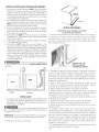
NEMA 10-30R NEMA 14-30R
GASDryer
CIRCUIT- Individual 15 amp. branch circuit fused with a 15
amp. maximum time delay fuse or circuit breaker.
POWER SUPPLY- 3 wire, 120 volt single phase, 60 Hz,
Alternating Current.
POWER SUPPLYCORD - The dryer isequipped with a 120
volt 3-wire power cord_
NOTE: Do not under any
circumstances remove
grounding prong from
plug. kk
GROUNDING PRONG
EXHA US T SYS TEM REQ UIREMENTS
Use only 4 inch (10.2 cm) diameter (minimum) rigid or flexible
metal duct and approved vent hood which has a swing-out
damper(s) that open when the dryer is in operation. When the
dryer stops, the dampers automatically close to prevent drafts
and the entrance of insects and rodents. Toavoid restricting the
outlet, maintain a minimum of 12 inches (30.5 cm) clearance
between the vent hood and the ground or any other obstruction.
The following are specific requirements for
proper and safe operation of your dryer. Failure to follow
these instructions can create excessive drying times and
fire hazards.
Do not install a clothes dryer with flexible
plastic venting materials. If your present system is made up
of plastic duct or metal foil duct, replace it with a rigid or flexible
metal duct. In Canada and the United States if metal (foil type)
duct is installed, it must be of a specific type identified by the
appliance manufacturer as suitable for use with clothes dryers
and in the United States must also comply with the Outline for
Clothes Dryer Transition Duct, UL standard 2158A. Flexible
venting materials are known to collapse, be easily crushed and
trap lint. These conditions will obstruct clothes dryer airflow and
increase the risk of fire. Ensure the present duct is free of
any lint prior to installing dryer duct.
!!!iiiii_iiii
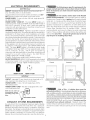
DO DON'T
© © I
Correct Incorrect
ii_i_i:iiiiiiiiiiiiiiiiiiiiiiiiiiiiiiiiiiiiiiiiiiiiiiiiiiiiiiiiiiiiiiiiiiiiiiiiiiiiiiiiiiiiiiiiiiii_iiii_
DON'T
C
Incorrect
- Risk of Fire - A clothes dryer must be
exhausted outdoors. Do not exhaust dryer into a chimney, a
wall, a ceiling, an attic, a crawl space or any concealed space
of a building A clothes dryer produces combustible lint. If the
dryer is not exhausted outdoors, some fine lint will be expelled
into the laundry area. An accumulation of lint in any area of the
home can create a health and fire hazard. The dryer must be
connected to an exhaust outdoors. Regularly inspect the
outdoor exhaust opening and remove any accumulation of lint
around the outdoor exhaust opening and in the surrounding
area.

Do not allow combustible materials (for
example: clothing, draperies/curtains, paper) to come in
contact with exhaust system. The dryer MUST NOT be
exhausted into a chimney, a wall, a ceiling, or any concealed
space of a building which can accumulate lint, resulting in a fire
hazard.
Exceeding the length of duct pipe or
number of elbows allowed in the "MAXIMUM LENGTH"
charts can cause an accumulation of lint in the exhaust system.
Plugging the systemcould create afire hazard, aswell asincrease
drying times.
Do not screen the exhaust ends of the vent
system, nor use any screws, rivets or other fastening means
that extend into the duct and catch lint to assemble the
exhaust system. Lint can become caught in the screen, on the
screwsor rivets, clogging the duct work and creating afire hazard
aswell as increasing drying times. Use an approved vent hood
to terminate the duct outdoors, and sealalljoints with duct tape.
All male duct pipe fittings MUSTbe installed downstream with
the flow of air.
Explosion hazard. Do not install the dryer
where gasoline or other flammables are kept or stored. If
the dryer is installed in a garage, it must be a minimum of 18
inches (45.7 cm) above the floor. Failure to do so can result in
death, explosion, fire or burns.
I. Connect an inclined or digital manometer between the dryer
and the point the exhaust connects to the dryer.
2. Set the dryer timer and temperature to air fluff (cool down)
and start the dryer.
3. Read the measurement on the manometer.
4. The system back pressure MUSTNOTbe higher than 0.75
inches of water column. If the system back pressure is
less than 0.75 inches of water column, the system is
acceptable. If the manometer reading is higher than 0.75
inches of water column, the system is too restrictive and
the installation is unacceptable.
Although vertical orientation of the exhaust system is
acceptable, certain extenuating circumstances could affect
the performance of the dryer:
• Only the rigid metal duct work should be used.
• Venting vertical through a roof may expose the exhaust
systemto down drafts causing an increase in vent restriction.
• Running the exhaust system through an uninsulated area
may cause condensation and faster accumulation of lint.
• Compression or crimping of the exhaust system will cause
an increase in vent restriction.
The exhaust system should be inspected and cleaned a mini-
mum of every 18 months with normal usage. The more the
dryer is used, the more often you should check the exhaust
system and vent hood for proper operation.
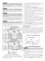
MAXIMUM LENGTH
of 4" (10.2 cm) Dia. Rigid Metal Duct
VENT HOOD TYPE
Number (Preferred)
Tur., "4
(10.2 cm) (6.35 cm)
0 60 ft.(l&28 m) 48 ft.(14.63 m)
1 52 ft.(15.84 m_ 40 ft.(12.19 m)
2 44 ft.(13.41 m) 32 ft. (9.75m)
3 32 ft.(9.75 m) 24 ft. (7.31 m)
4 28 ft.(8.53 m) 16ft. (4.87m)
MAXIMUM LENGTH
Number of 4" (10.2 cm) Dia. Flexible Metal Duct
VENT HOOD TYPE
of (Preferred)
-4 4"F "F-
(10.2 cm) (6.35 cm)
0 30ft. (9.14m) 18ft.(5.49m)
1 22 ft. (6.71 m) 14 ft. (4.27 m}
2 14 ft. (4.27 m) 10 ft. (3.05 m)
3 NOT RECOMMENDED
INSTALL MALE FiTTiNGS IN CORRECT DIRECTION
In installations where the exhaust system isnot described in the
charts, the following method must be used to determine if the
exhaust system isacceptable:
EXHAUST DIRECTION
All dryers shipped from the factory are set up for rear exhausting.
However, on electric dryers, exhausting can be to the right or left
side of the cabinet or the bottom of the dryer On gas dryers,
exhausting can be to the right side of the cabinet orthe bottom of
the dryer. Directional exhausting can be accomplished by installing
Exhaust Kit, P/N 131456800, available through your parts
distributor Followthe instructions supplied with the kit
EXHAUST DUCT LOCATING DIMENSIONS
/-SAMEASOTHERSiDE
_"_" ./- 5 7/8"
j
GAS SUPPLY REQUIREMENTS
Replace copper connecting pipe that is not
plastic-coated. Stainless steel or plastic-coated brass MUST
be used.
1 Installation MUST conform with local codes, or in the absence
of local codes, with the National Fuel GasCode, ANSI Z2231
(latest edition)
2 The gas supply line should be of 1/2 inch (127 cm) pipe
3. If codes allow, flexible metal tubing may be used to connect
your dryer to the gas supply line. The tubing MUST be
constructed of stainless steel or plastic-coated brass.
4 The gas supply line MUSThave an individual shutoff valve
4

5. A 1/8 inch (0.32 cm) N.P.T.plugged tapping, accessible for test gauge connection, MUST be installed immediately upstream
of the gas supply connection to the dryer.
6. The dryer MUST be disconnected from the gas supply piping system during any pressuretesting of the gassupply piping system
at test pressures in excess of I/2 psig (3.45 kPa).
7. The dryer MUSTbe isolated from the gas supply piping system during any pressure testing of the gas supply piping system
at test pressures equal to or lessthan
1/2 psig (3.45 kPa).
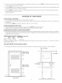
LOCATION OF YOUR DRYER
DO NOT INSTALL YOUR DRYER:
1. In an area exposed to dripping water or outside weather conditions.
2. In an area where it will come in contact with curtains, drapes, or anything that will obstruct the flow of combustion and
ventilation air.
3. On carpet. Floor MUSTbe solid with a maximum slope of I inch (2.54 cm).
INSTALLATION IN RECESSOR CLOSET
1. A dryer installed in a bedroom, bathroom, recessor closet, MUST be exhausted outdoors.
2. No other fuel burning appliance shall be installed in the same closet asthe Gasdryer.
3. Your dryer needs the space around it for proper ventilation.
DO NOT install your dryer in a closet with a sofid door.
4. A minimum of 120 square inches (774.2 square cm) of opening, equally divided at the top and bottom of the door, is required.
Air openings are required to be unobstructed when a door isinstalled. A Iouvered door with equivalent air openings for the full
length of the door isacceptable.
MINIMUM INSTALLATION CLEARANCES - Inches (cm)
SIDES REAR TOP FRONT
Alcove 0(0cm) 0(0cm)
Closet 0 (0 cm) 0 (0 cm) 1 (2.54 cm)
Closet door ventilation required: 2 Iouvered openings each 60 square inches (387 square centimeters) -- 3 inches (7.6 cm) from
bottom and top of door.
This dryer MUST be exhausted outdoors.
5. The following illustrations show minimum clearance dimensions for proper operation in a recessor closet installation.
II
--,,41_o" (o cm)
H
ii
0" (0 cm)
II
,, 0" (0 cm)
1" (2.54 cm) _11 _
II ii
II _11 _
CLOSET DOOR

48.5"
(123.19cm)
l
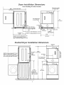
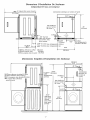
Dryer Installation Dimensions
Free=Standing & Under Counter
To clear open door
(72.39cm)
28.5"
Gas supply pipe
on rear of unit
\
(5. 72cm)
2.25"
5.0" (12.7cm)
Center line height
rear, right, left ;_:!::F;;F
vent
4.375" To side exhausts (11.12cm)
5.875" To base exhaust (14.93cm)
27.25 to front of cabinet (69.22cm)
27.75 to clear knobs (70.49cm)
28.5 to clear door handle (72.39cm)
0 o ,'_,_ #
l
_ -p
|(6.03cm) ! 13.5"
To rear &
base exhaus
27.0"
q
(68.58cm)
Electrical supply
on rear of unit
/
36"
"91.44cm)
(34.29cm)
Stacked Dryer Installation Dimensions
T
72.00"
(11.12cm) (182.88cm)
4.375"
Side
exhausts
41.00"
(104.14cm)
Center line
height for rear,
right, left vents
1
28.25" to front of cabinet(71.76cm)
28.75" to clear knobs (73.03cm)
29.5" to clear door handle
49" to clear open door (124.46cm)
9
(34.29cm) !
13.5"
Gas supply pipe
on rear of unit
T "_i•
38.25"
(97.16cm)
(68.58cm)
27.0"
LU O
6

MOBILE HOME INSTALLATION
I. DryerMUSTbe exhausted outside (outdoors, not beneath the
mobile home) using metal ducting that will not support
combustion. Metal ducting must be 4 inches (10.16 cm) in
diameter with no obstructions. Rigid metal duct ispreferred.
2. If dryer is exhausted through the floor and area beneath the
mobile home isenclosed, the exhaust systemMUSTterminate
outside the enclosure with the termination securely fastened
to the mobile home structure.
3. When installing a gas dryer into a mobile home, a provision
must be made for outside make up air.This provision isto be
not lessthan twice the area of the dryer exhaust outlet.
4. This dryer MUST be fastened to the floor. Mobile Home
Installation Kit No. 346764 isavailable from your dealer.
5. Refer to pages 2 and 3 for other important venting
requirements.
6. Installation MUST conform to current Manufactured Home
Construction & Safety Standard (which isa FederalRegulation
Title 24 CFR-Part 32-80) or when such standard is not
applicable, with American National Standard for Mobile Homes.
Thedryer isdesigned under ANSIZ21.5.1 or ANSI/
UL2158 - CAN/CSA C22.2 (latest editions) for HOME USEonly.
Correct Incorrect
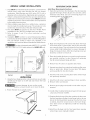
UNPACKING
1. Using the four shipping carton corner posts(two on each side),
carefully laythe dryer on its left side and remove the foam
shipping base.
To prevent damage, do not use the control
panel as a means to pick up or move the dryer.
2. Return the dryer to an upright position.
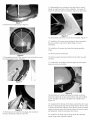
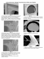
REVERSING DOOR SWING
Sofid Door Reversing Instructions:
1. Open door and remove four (4) plugs in the door opening
opposite the hinges. Retain all parts for uses later, unless
otherwise noted. Note: Usecare in removing plugs in not
scratching paint on
REMOVE 4 SCREWS
(ONE FROM EACH
HINGE FIRST)
Begin removing the four (4) screws that attach the hinge
to the front panel. For best results, start by only removing
one screw per hinge. Then only loosen the two remaining
screws while firmly holding door to prevent damage to
hinge, front panel or door. After the remaining screws are
loosened, continue to remove all.
3. Placedoor handle side down on a towel or pad to prevent
any possible scratches to door. Remove all remaining
four (4) screws between hinge and door.
4. Remove four (4) screws on opposite side of door.
5. Separate inner door from outer door byplacing a flat screw
driver or putty knife. Rotate the inner door 180 degree
and reassemble the two door halves.
6. Install four (4) screws securing door halves where hinge
was previously attached.
7. Install four (4) screws securing hinge to door assembly.
8. Remove striker and discard.
9. Remove square plug and reinstall in hole striker was just
removed.
10. Install striker (included in literature bag) into hole square
plug was previously installed.
11.Grasping firmly the top of the door, position the door near
the door opening and align the top hinge hole to the top
hole in the front panel door opening. Once the first screw
is started, attach the second screw to the lower hinge.
Once both screws are tightened, install the remaining
two screws.
12.Install four (4) plugs into the front panel door opening
where hinges were originally installed.

Figure 1
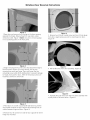
Window Door Reversal Instructions
1.0pen door and remove four (4) plugs in the door opening
opposite the hinges. Retain all parts for uses later, unless
otherwise noted. (Figure 1) Note: Use care in removing plugs
in not scratching paint on the front panel.
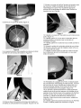
Figure 2
Figure 4
5. Remove two (2) door handle screws and two (2) hole plugs
from door. Again taking care not to scratch paint on door.
(Figure 4)
2. Begin removing the four (4) screws that attach the hinge to
the front panel. (Figure 2) For best results, start by only
removing one screw per hinge. Then only loosen the two
remaining screws while firmly holding door to prevent damage
to hinge, front panel or door. After the remaining screws are
loosened, continue to remove all.
Figure 3
Figure 5
6. Pull handle away from door assembley. (Figure 5)
Figure 6
7. Separate the outer door from the inner door assembly with
a putty knife or flat screw driver. (Figure 6)
3. Place door on a towel or pad handle side down to prevent
any possible scratches to door. Remove all remaining four (4)
screws between hinge and door. (Figure 3)
4. Remove four (4) screws from side of door opposite of where
hinge was mounted.

Figure 7
11. Reassemble lens to transition ring with holes to install
handle on right-hand side of door assembly. For proper fit
insure the retention tabs on transition ring are on top of lens
8. Remove lens locating screw. (Figure 7)
Figure 8
9. Disengaging several of the retention tabs and pull lens away
from the transition ring. (Figure 8)
Figure 9
Figure 10
Figure 11
12. Reassemblyouter door to inner door assembly. (Figure 11)
13. Install four (4) screws securing hinge to door assembly in
the new location, take note to place hinge in correct
orientation.
14. Install four (4) screws into holes that had secured the
hinge.
15. Remove striker and discard.
16. Remove square plug and reinstall in hole striker was just
removed.
17. Install striker (included in literature bag) into hole square
plug was previously installed.
10. Remove two (2) transition ring plugs and reinstall on
previous handle side. (Figures 9 and 10)
Figure 12
18. Reinstall door handle by placing the handle mounting
bossesthrough holes in lens and transition ring and installing
screws through inner door and tighten into handle bosses.
(Figure 12).
19. Grasping firmly the top of the door, position the door near
the door opening and align the top hinge hole to the top hole
in the front panel door opening. Once the first screw isstarted,
attach the second screw to the lower hinge. Once both screws
are tightened, install the remaining two screws.
20. Install four (4) plugs into the front panel door opening
where hinges were originally installed.

ELECTRICAL INSTALLATION
I ELECTRICDryer
The following are specific requirements for
proper and safe electrical installation of your dryer. Failure
to follow these instructions can create electrical shock and/
or a fire hazard.
This appliance MUST be properly grounded.
Electrical shock can result if tile dryer is not properly grounded.
Follow the instructions in this manual for proper grounding.
Do not use an extension cord with this dryer.
Someextension cords are not designed to withstand the amounts
of electrical current this dryer utilizes and can melt, creating
electrical shock and/or fire hazard. Locate the dryer within reach
of the receptacle for the length power cord to be purchased,
allowing some slack in the cord. Refer to the pre-installation
requirements in this manual for the proper power cord to be
purchased.
A U.L. approvedstrain reliefmustbe installed
onto power cord. If tile strain relief is not attached, tile cord
can be pulled out of the dryer and can be cut by any movement
of the cord, resulting in electrical shock.
Do not use an aluminum wired receptacle
with a copper wired power cord and plug (or vice versa).
A chemical reaction occurs between copper and aluminum and
can cause electrical shorts. The proper wiring and receptacle
is a copper wired power cord with a copper wired
receptacle.
NOTE: Dryersoperating on 208 volt power supplywill have longer
drying times than operating on 240 volt power supply.
j Canadian ELECTR/CDryer J
_ Improper connection of tile equipment grounding
conductor can result in a risk of electrical shock. Check with a
licensedelectrician ifyou arein doubt asto whether the appliance
isproperly grounded.
Fora arounded, cord-connected dryer:
1. The dryer must be grounded. Inthe event of a malfunction or
breakdown, grounding will reduce the risk of electrical shock
by a path of least resistance for electrical current.
Sinceyour dryer isequipped with a power supply cord having
an equipment-grounding conductor and a grounding plug,
the plug must be plugged into an appropriate outlet that is
properly installed and grounded in accordance with all local
codes and ordinances. If in doubt, call a licensed electrician.
Do not modify plug provided with the appliance.
ALL GAS Dryers
1. The dryer is equipped with a three-prong (grounding) plug
for your protection against shock hazard and should be
plugged directly into a properly grounded three-prong
receptacle. Do not cut or remove the grounding prong from
the plug.
GROUNDING REQUIREMENTS
USA ELECTR/CDryer i
Improper connection of the equipment grounding
conductor can result in a risk of electrical shock. Check with a
licensedelectrician ifyou are in doubt asto whether the appliance
isproperly grounded.
For a grounded, cord-connected dryer:
I. Tile dryerMUSTbe grounded. Inthe event of a malfunction
or breakdown, grounding will reducethe riskof electricalshock
by a path of least resistance for electrical current.
2. If your dryer isequipped with a power supply cord having an
equipment-grounding conductor and a grounding plug, the
plug MUST be plugged into an appropriate, copper wired
receptacle that is properly installed and grounded in
accordance with all local codes and ordinances. If in doubt,
call a licensed electrician. Do not modify plug provided
with the appliance.
For a permanently connected dryer:
I. ThedryerMUSTbe connected to a grounded metal, permanent
wiring system; or an equipment grounding conductor must be
run with the circuit conductors and connected to the
equipment-grounding terminal or lead on the appliance.
10

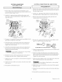
ELECTRICALCONNECTIONS ELECTRICALCONNECTIONS FOR 4- WIRE SYSTEM
FOR 3- WIRESYSTEM
USA ELECTRICDryer
1. Remove the screws securing the terminal block access
cover and the strain relief mounting bracket located on the
back of the dryer upper corner.
2. Install a U.L approved strain relief into the power cord
entry hole of the mounting bracket. Finger tighten the nut
only at this time.
GREEN
SCREW
NEUTRAL
GROUND
WIRE
SILVER
TERMINAL
USA ELECTR/CDryer
l
1. Remove the screws securing the terminal block accesscover
and the strain relief mounting bracket located on the back of
the dryer upper corner.
2. Install a U.L approved strain relief in the entry hole of the
mounting bracket. Fingertighten the nut only at this time.
3. Remove the ground wire from the green ground screw
located above the terminal block.
GREEN POWER CORD
GREEN
SILVERTERMINAL
SCREW TERMINAL
BLOCK
tUTTIGHTEN NUT
TO THESE
_READS
BRACKET POWER CORD
3. Thread a U.L approved 30 amp. power cord, NEMA 10-30
type SRDT,through the strain relief.
4. Attach the power cord neutral (center wire) conductor to
the silver colored center terminal on the terminal block.
Tighten the screw securely.
5. Attach the remaining two power cord outer conductors to
the outer brasscolored terminals on the terminal block.
Tighten both screws securely.
Do not make a sharp bend or crimp wiring/
conductor at connections.
6. Reattach the strain relief mounting bracket to the back of
the dryer with two screws. Tighten screws securely.
7. Tighten the screws securing the cord restraint firmly against
the power cord.
8. Tighten the strain relief nut securely sothat the strain relief
does not turn.
9. Reinstall the terminal block cover.
TIGHTEN
NUT
GROUND WHITE TO THESE
WIRE NUT -HREADS
STRAIN
RELIEF
BRACKET,.
POWER
CORD
4. Thread a U.L approved 30 amp power cord, NEMA 14-30
type STor SRDTthrough the strain relief.
.
TYPICAL 4
TYPICAL 4 BLACK
C_WHITE
_,_I_ED
30 AMP NEMA 14-30 TYPE SRDT OR ST _GREEN
Attach the green power cord ground wire to the cabinet with
the green ground screw.
.
Attach the white (neutral) power cord conductor from the
power cord and the neutral ground wire from the dryer harness
to the silver-colored center terminal on the terminal block.
Tighten the screw securely.
7. Attach the red and black power cord conductors to the outer
brass-colored terminals on the terminal block.
.
Do not make a sharp bend or crimp wiring/
conductor at the connections.
Tighten the screws securing the cord restraint firmly against
the power cord.
9. Tighten the strain relief nut securely so the strain relief does
not turn.
10.Reinstall the terminal block accesscover.
11 Printed in U.S.A.

GAS CONNECTION
1. Remove the shipping cap from gas pipe at the rear of the
dryer.
NOTE: DO NOT connect the dryer to L.P. gas service
without converting the gas valve. An L.R conversion kit
must be installed by a qualified gas technician.
2. Connect a I/2 inch (1.27 cm) I.D. semi-rigid or approved
pipe from gas supply line to the 3/8 inch (0.96 cm) pipe
located on the back of the dryer (seepages 6 and 7). Usea
1/2 inch to 3/8 inch (1.27 cm to 0.96 cm) reducer for a
connection. Apply an approved thread sealerthat isresistant
to the corrosive action of liquefied gases on all pipe
connections.
3. Open the shutoff valve in the gassupply line to allow gasto
flowthrough pipe.
4. Testall connections by brushing on a soapy water solution.
VALVE OPEN I
GAS FLOW POSITION
NEVER test for gas leaks with an open flame.
GENERAL iNSTALLATiON
I. Connect the exhaust duct to outside exhaust system (see
pages 3 and 4). Use duct tape to seal all joints.
2. With the dryer in its final position, adjust one or more of the
legs until the dryer is resting solid on all four legs. Placea
level on top of the dryer. The dryer MUST be level and
resting solid on all four legs.
3. Plug the power cord into a grounded outlet. NOTE: Check
to ensure the power is off at circuit breakedfuse box before
plugging the power cord into the outlet.
4. Turn on the power at the circuit breaker/fuse box.
Before operating the dryer, make sure the
dryer area is clear and free from combustible materials,
gasoline, and other flammable vapors. Also see that
nothing (such as boxes, clothing, etc.) obstructs the flow
of combustion and ventilation air.
7. Place these instructions in a location near the dryer for
future reference.
NOTE: A wiring diagram is located inside the dryer console
or under the top panel.
8. To stack your dryer on a compatible washer, visit web site
www.frigidaire.com, call your local dealer or call the Toll
Freenutuber (1- 8o0- 444- 4944)to find your localdistributor
to purchase stacking kit accessory part number STACKIT2.
REPLACEMENT PARTS
Pedestal
A pedestal accessory, Model No, NLPWD15 (White),
NLPWD15GB (Glacier Blue), NLPWD15P (Platinum) and
NLPWD15E (Black), specifically designed for this dryer may be
used when elevating the dryer for ease of use. Failure to use
accessoriescertified bythe manufacturer could result in personal
injury, property damage or damage to the dryer.
If replacements parts are needed for your dryer, contact the
source where you purchased your dryer, call 1-800-944-9044,
or visit our website, www.frigidaire.com, for the Frigidaire
Company Authorized Parts Distributor nearest you.
Labelall wires prior to disconnection when servicing
controls. Wiring errors can cause improper and dangerous
operation. Verify proper operation after servicing.
Destroy the carton and plastic bagsafter the dryer
isunpacked. Children might usethem for play. Cartons covered
with rugs, bedspreads, or plastic sheets can become airtight
chambers causing suffocation. Placeall materials in a garbage
container or make materials inaccessible to children.
The instructions in this manual and all other
literature included with this dryer are not meant to cover every
possible condition and situation that may occur. Good safe
practice and caution MUSTbe applied when installing, operating
and maintaining any appliance.
5. Run the dryer through a cycle check for proper operation.
NOTE: On gas dryers, before the burner will light, it is
necessary for the gas line to be bled of air. If the burner does
not light within 45 seconds the first time the dryer isturned on,
the safety switch will shut the burner off. If this happens, turn
the timer to "OFF" and wait 5 minutes before making another
attempt to light.
6. If your dryer does not operate, please review the "Avoid
Service Checklist" located in your Use and Care Guide be-
fore calling for service.
12

Table des mati res
Avant I'installation ............................................................................................................................................................ 13
Installation dectrique .................................................................................................................................................... 14
Evacuation de I'air.................................................................................................................................................. 14-I 5
Alimentation en gaz......................................................................................................................................................... 16
Emplacement de la secheuse........................................................................................................................................... 16
Dimensions de I'emplacement ................................................................................................................................. 17
Installation dans une maison mobile .................................................................................................................................. 18
D_ballage ..................................................................................................................................................... 18
Porte R6versible ............................................................................................................................................... 18-20
Installation electrique ....................................................................................................................................................... 21
Mise a la terre ................................................................................................................................................................ 21
Branchement 61ectrique - Installation a 3 fils ........................................................................................................................ 22
Branchement 61ectrique - Installation a 4 ills ........................................................................................................................ 22
Installation .......................................................................................................................................................... 23
Pi6ces de rechange ......................................................................................................................................................... 23
Mesures de S curit Importantes
L'installation et /e service de/a Secheuse de v_tements doivent @treeffectues par un installateur qualifi_, I'agence de
service ou le fournisseur de gaz. Installez la Secheuse de v@tement selon les instructions du fabricant et les codes Iocaux.
Avant de commencer, lire attentivement le present document. Cela simplifiera I'installation et assurera la pose
correcte et securitaire de la s_cheuse. Apres I'installation, laisser ce document _ proximite de la secheuse pour r_ference
future.
REMARQUE :L'alimentation dectrique de lasecheusedoit respecter lescodes et ordonnances Iocaux ainsique 1'6dition laplus r6cente
du Code ANSI/NEPA70, ou au Canada, le Code canadien d'_lectricit_, ACNOR C22. I, partiel.
REMARQUE : L'alimentation en gaz de la s_cheusedoit respecter lescodes et ordon nances Iocaux ainsique 1'6dition laplus r6cente du
Code ANSIZ223. I, ou au Canada, le code CAN/ACG B149.1-2000.
REMARQUE : Las_cheuse est conc;ueconformement au code ANSI Z21.5.1 ou ANSI/UL 2158 - CAN/ACG C22.2 No. 112 (l'_dition la
plus r6cente) pour un USAGEDOMESTIQUEseulement. Cette secheuse n'est pasrecommand6e pour utilisation commerciale, comme
par exemple un restaurant ou un salon de coiffure, etc.
Votre s curit et celle des autres est tr s importante.
Nous donnons de nombreux messagesde s_curite irnportants dans cemanuel et survotre appareil menager. Assurez-vous de toujours
lire tous les messagesde s_curite et de vous y conformer.
Voici le symbole de raiseen garde. Ce symbole met en garde contre lesrisques pouvant entra;ner le d6c6s ou des blessures
soi ou auxautres. Tousles messages relatifs _ la s_curit_ sont pr6c6d6s du symbole de raise en garde et du terme <<DANGER
>>ou <<AVERTISSEMENT>>.Ces termes signifient •
L'utilisateur sera tue gravement bless6 s'il ne suit pas ces directives.
_ L'utilisateur peut 6tre tu6 ou gravement bless6 s'il ne suit pas ces directives.
Tous les messages relatifs _ la securit_ indiquent le risque, comment r_duire le risque de blessure et ce qui peut
survenir si on ne suit pas les directives.
RISQUE D'INCENDIE. Pour votre s_curit_, suivre lesdirectives _nonc_es dans le present guide afin de minimiser
les risques d'incendie, d'explosion, de dommages materiels, de blessures et de mort. GARDEZCES INSTRUCTIONS.
- Ne pasentreposer ni utiliser d'essence ou autres liquides ou produits inflammables _ proximit_ de cette s_cheuse ou de tout
autre appareil m_nager.
- QUE FAIRE S'IL YA UNE ODEUR DE GAZ
• Ne mettre en marche aucun appareil .
Ne toucher aucun interrupteur @lectrique; n'utiliser aucun t@l@phonedans I'immeuble.
Faire sortir tousles occupants de la piece, de I'immeuble ou de la zone avoisinante.
Appeler la fournisseur de gaz immediatement en utilisant le telephone d'un voisin. Suivre les directives du fournisseur de
gaz.
S'il est impossible de joindre le fournisseur de gaz, appeler le service de protection des incendies.
L'installation et les r@parationsdoivent 6tre effectu@espar un service de r@paration, un technicien qualifi@ou le fournisseur de gaz.
#
AVANT L NSTALLATION
Outils et materiel requis pour I'installation :
I. Tournevisa pointecruciforme
2. Pincemultiprise
3. Niveau demenuisier
4. Tournevis _ pointe plate oua lame droite
5. Rubanadhesifpourconduits
6. Conduite en m_tal rigide ou souple de 10,2 cm (4 po)
7. Bouche d-_vacuation d'air
8. Ruban ou p_te d'@tancheit_ porjoints filetes (modUle a gaz)
9. Couteau a masticen plastique
13

INSTALLATION ELECTRIQUE
i SecheusesE'ZECTRIOUES ]
CIRCUIT- Derivation distincte de 30 A avecfusibles a retardement
ou disjoncteurs d'au 30 A.
Utilisez des circuits avec un disjoncteur ou fusible s6par6 pour les
machines a laver et s6cheuses, et NE PASfaire fonctionner une
machine a laver et une s6cheuse sur un m6mecircuit.
ALIMENTATIONELECTRIQUE- 3 fils,240 volts, une phase,60 Hz,
courant alternatif. (Canada -240 volts, une phase, 60 Hz, courant
alternatif.)
CORDON D'ALIMENTATION ELECTRIQUE-LasecheuseDOIT6tre
reli_ea un cordon d'alimentation dectrique a3 conducteurs NEMA
10-30 detype SRDTd'u ne capacite minimale de 240 volts, courant
alternatif, 30 A, avec fiche en L a 3 broches pleines ou repli_es
conc_ue pour le branchement d'une secheuse.
AVERTISSEMENT-Risque de choc _lectrique. Unappareil mis
a la terrea I'aide d'un lien ou c_bleconducteur neutre. La mise a
la terre a I'aide d'u n conducteur ou cable neutre est interdite darts
lescas suivants : (1) les installations de nouveau circuit d_vir_ (2)
lesmaisons mobiles (3) lesv_hicules r_cr_atifs ou caravanes et (4)
lesr_gions o0 lescodes Iocaux interdisent la mise a la terre a I'aide
d'un cable ou conducteur neutre. (1) D_branchez le conducteur
ou cabledu neutre, (2)utilisez laborne de misea laterre ou lecable
de mise a laterre de I'appareil conform_ment auxcodes Iocaux et
(3) connectez ou branchez la borne neutre ou lec_ble au neutre du
circuit d_vir_de lamani_re habituelle(si I'appareil doit 6treconnect6
a I'aide d'un cordon, utilisez un cordon a 4 cables ou fils pour ce
faire). N'UTILISEZQUEDESCABLESOUFILSENCUIVRE.
Elle DOlT 6tre reli@ea un cordon d'alimentation @lectrique a
4 conducteurs NEMA 14-30 de type SRDTou ST(au besoin) d'une
capacite minimale de 240 volts, courant alternatif, 30 A, avecfiche
en La 4 broches pleines ou repli6es conc;uepour le branchement
d'une s@cheuse. Se reporter a la section BRANCHEMENT
ELECTRIQUED'UNE INSTALLATIONA 4 FILS.
(Canada - Cordon d'alimentation a4 fils branch@a la s@cheuse.
PRISE- Prise NEMA 10-30R situ@ede fat;on ace que le cordon
d'alimentation @lectriquesoit accessible une fois las_cheuse en
place. (Canada - prise NEMA de 14-30R.)
ALIMENTATIONI I , ^ .
ELECTRIQUE [_;-_ "_BOITE A FUSIBLES PRINCIPALE NEUTRE A 3
I _ FILS 120-2.40 VOLTS 60 CYCLES
I,_,J,_'_ FUSISLESARETARDEMENTOU
_DISJONCTEUR DE 30 A
_ FILNEUTRE
PRISE MURALE
(CUlVRE)
SOUS RESERVE DES EMA 10-30R (CUIVRE)
EXIGENGES LOCALES
CIRCUIT- Derivation distincte de 15 A avecfusible a retardement
ou disjoncteur d'au plus 15 A.
ALIMENTATION¢LLECTRIQUE- 3 fils, 120volts, une phase,60 Hz,
courant altem atif.
CORDON D'ALIMENTATION ELECTRIQUE - La s_cheuse est
pourvue d'un cordon d'alimentation _lectrique a3 fils de 120 volts,
REMARQUE : II ne faut { _J _l] _
broche de mise a la I \ %
\ ( j B,ROCHE DE M!SE
_ A LA TERRE
14
L'VA CUAT!ON DE L'AIR
Utiliser uniquement une conduite en m_tal rigide ou flexible de
10,2 cm (4 po) de diam_tre (minimu m)ainsi qu'u ne grille de sortie
approuv_e pourvue de clapets qui s'ouvrent Iorsque la s_cheuse
fonctionne. Quand la s_cheuse s'arr6te, les clapets se ferment
automatiquement pour _viter lescourantsd'air etI'entr_e d'insectes
ou de rongeu rs.Afin de ne pasobstruer I'_vacuation deI'air, laisser
une distance minimum de 30,5 cm (12 po) entre la grille de sortie
et le sol ou tout autre obstacle.
Les mises en garde quisuiventse rapportent
directement au fonctionnement correct et securitaire de la
secheuse. Toute derogation a ces mises en garde pourrait
ralentir le s_chage et entrainer des risques d'incendie.
__N'installez pas la Secheuse avec des materiels de
ventilation en rnati#res plastiques flexibles.
Silaconduite existante est en plastique ou en papier metallique, la
_par une conduite en m_tal rigide ou flexible. Au Canada
etaux Etats-Unissileconduit estde m_tal (type feuille d'aluminium),
celui-ci doit _tre d'un type sp_cifique identifi_ par lefabricant,
recommand_ pour I'utilisation avec des S_cheuses; et aux Etats-
Unis il doit en outre remplir la norme UL215% Lesmat_riaux de
ventilation flexibles peuvent s'abimer facilement et recueillir du
duvet. Cesconditions obstrueront lacirculation d'air de laSecheuse
de v_tements et augmenteront lerisque d'incendie. S'assurer
qu'il n'y a pas de charpie clans la conduite existante avant
d'installer la conduite de la s_cheuse.
_- Risque d'incendie- une S_cheuse de v_tement dolt _tre
aere & I'air libre, N'a_rez pas la Secheuse dans une chemin_e,
une paroi, un plafond, un espaceferm_ ou aucun espace cach_ du
batiment. Une secheusea linge produit de lacharpie combustible.
SiFairn'_taitpasrepousseal'ext_rieurdelamaison de petites
particules de charpie seretrouveraient dans lapiece o0 est install_e
la secheuse. Toute accumulation de charpie dans la maison peut
presenter desrisques pour la sant_ et desrisques d'incendie.
NON
0
I
Correct Incorrect
OUI
Correct

La s_cheuse dolt _tre connectee a une bouche d'_vacuation
vers I'exterieur du b_timent ou de I'immeuble. Vous devez
inspecter r_guli_rement I'_vent exterieur et enlever toute
accumulation de charpie autour de I'_vent et dans la cavite du
conduit d'_vacuation.
ONe laisseraucun mat_riau inflammable (comme desv6tements,
destentures, des rideaux ou du papier) entrer en contact avec les
conduits d'@acuation.
_ Auqmenter laIonqueur du conduit riqideou lenombrede coudes
permis au tableau _LONGUEURMAXIMUM_> risque de r_duire la
capacite d'_vacuation du circuit. Obturer le circuit peut crier un
risque d'incendie et augmenter letemps de s_chage.
P._q N'obstruez paslesextr_mites du tube de ventilation, niutilisez
desvis, rivets ou autres movens de fixation qui peuvent obstruer le
conduitetrecueillirdu duvet. L'engorgementsubs_quentrisquerait
de ralentir letemps des_chage,voire decauser un incendie. Installer
une bouche d'_vacuation approuv_e a I'ext_rieur et sceller tousles
joints _ I'aide d'un ruban adh_sif a conduits. Tousles raccords de
conduit males DO/VENT_tre install_s dans lesensde la circulation
d'air.
Risques d'explosion, Ne pas installer la
s_cheuse_un endroit o0 I'ongardedelagazolineou tout autreproduit
inflammable. Si las_cheuse est install_e dans un garage, elle dolt
6tre_ un minimum de45,7 cm (18 po)au-dessusdu plancher.Toute
d_rogation pourrait provoquer la mort, I'explosion, I'encendie ou
lesbr01ures.
Nombre de
coudes ,_
90°
0
1
2
3
4
Nornbre de
coudes a
90°
0
1
2
3
LONGUEUR MAXIMUM
d'une conduite en m_tal rigide de
10,16 cm (4 po) de diam.
TYPEDE GRILLEDE SORTIE
(Recommand_)
cm
!4 po)
18,28m
15,84m
13,41m
9,75 m
8,53 m
volet
(60 po) 14,63 rr
(52 po)
(44 po)
(32 po)
(28 po)
(48 po)
12,19 m(40 po)
9,75 m (32 po)
7,31 m (24 po)
4,87 m (16 po)
LONGUEUR MAXIMUM
d'une conduite en metal flexible de
10_16 cm (4 po) de diam.
TYPEDE GRILLEDE SORTIE
{Recommande)
a volet
9,14 m (30 po)
6,71 m (22 po)
4,27 m (14 po)
5,49 m(18 po)
4,27 m (14 po)
3,05 m (10 po)
NON RECOMMANDE
15
POSERLESRACCORDSMALES DANS LA BONNE DIRECTION
Pour lesinstallations dont lecircuit d'evacuation n'est pasd6crit
dans lestableaux, il faut utiliser la m6thode suivante sile circuit
d'@acuation n'est pas acceptable:
I. Brancher un manom6tre digital ou a tube inclin6 entre la
s6cheuseet le raccord d'6vacuation de la secheuse.
2. Regler la minuterie de la s6cheuse et latemp6rature aair froid
(refroidissement) et d6marrez la secheuse.
3. Lire la mesure indiquee au manometre.
4. La bassepression ne dolt pas6tre sup6rieure a 0,75 pouce de
colonne d'eau. Sila bassepression est inf6rieure a 0,75 pouce
de colon ned'eau, lecircuit est acceptable. Sila lecture indique
une pression sup6rieure a 0,75 pouce de colonne d'eau, la
capacit6 du circuit est insuffisante et I'installation inacceptable.
Bien qu'un circuit vertical soit acceptable, certaines circonstances
attenuantes peuvent influencer la performance de la s6cheuse.
• Ilfaututiliseruniquementdesconduitsrigidesen m6tal.
• Unesortie sur un toit d'un circuit vertical peut exposer celui-ci a
un contre-tirage et ainsi r6duire sacapacite d'@acuation.
• L'isolant que dolt traverser un tel circuit peut causer de la
condensation et ainsir6duire lacapacite d'@acuation du circuit.
• Un circuit d'6vacuation comprim6 ou ondulant peut voir sa
capacite d'@acuation r6duite.
II faut inspecter le circuit d'@acuation et le nettoyer au moins
tousles 18mois d'utilisation normale. Pluslas6cheuseest utilis6e,
plus il faut proceder souvent a une v6rification du bon
fonctionnement du circuit d'@acuation etdu couvercle du registre
ou de I'6vent.
DiRECTiON DEL'EVA CUATION D'AIR
Touteslessecheusesempaquet6es par I'usinesont concuesde fac_on
ce que 1'6vacuation d'air se fasse a I'arri6re. Toutefois, dans le
cas des s6cheuses61ectriques, I'@acuation d'air peut sefaire sur
la droite ou sur la gauche du boitier ou encore, sous la s6cheuse.
Dans le casdess6cheuses _gaz, 1'6vacuation d'air peut sefaire sur
la droite du boitier ou sous la s6cheuse. On peut donc modifier
I'orientationdel'6vacuation d'airen installantun ensemble
d'@acuation d'air n° de pi6ce 131456800 disponible chez d'un
fournisseur de pi6cesagr66. Suivrelesdirectives qui accompagnent
cet ensemble.
EMPLACEMENT DESBOUCHESD'EVACUATIC)N
COMME SUR L'AUTRE COTE
J_,-" 5cm
_' ._(5 7/8 po)
34 crn
11 cm
9,5 cm
(3 3/4 po)
9,5 cm
(3 3/4 po)

ALIMENTAT!ON EN GAZ
Remplacer le tuyau de
raccordement en cuivre non recouvert de
plastique. II FAUT utiliser du laiton
inoxydable ou recouvert de plastique.
1. I_'installationDOITrespecter lescodes Iocaux,
ou s'il n'existe pas de codes Iocaux, le code
ANSIZ223. I (l'edition la plus recente) ou au
Canada, le Code actuel CAN/CGA B149.
2. La conduite d'alimentation en gaz dolt
mesurer 1,27 cm (1/2 po).
3. Silescodes le permettent, un tuyau en m_tal
flexible peut Ctre utilis_ pour connecter la
s_cheuse a I'alimentation en gaz. Le tuyau
DOIT6tre fabriqu_ en acierinoxydable ou en
cuivre avec un rev6tement de plastique.
4. La conduite d'alimentation en gaz DOlT
comporter unrobinet d'arr_t distinct.
5. Uneprisede0,32 cm(1/8 po)NPTaccessible
pour lebranchement d'un manom_treDOIT
Ctre install_e toutjuste en amont du
branchement de la conduite d'alimentation
en gaz sur la s_cheuse.
6. La s6cheuse DOlT Ctre debranchee de la
canalisation degaz pendanttoutev6rification
de pression de I'alimentation en gaz a des
pressionsqui d@assent3,45 kPa(1/2 Ib/po2).
7. La secheuse DOlT 6tre isol6e de la
canalisation degaz pendanttoutev6rification
de pression de I'alimentation en gaz a des
pressions_galesou inf_rieures _3,45 kPa(1/
2 Ib/po2).
EMPLA CEMENT DE LA SECHEUSE
NEPASINSTALLERLA SECHEUSE:
1. Dansunendroitexpos6aun6coulementd'eauouaux conditions
atmospl%riques.
2. Dansun endroit o0 elle serait en contact avecdesrideaux, draperies ou tout cequi
obstruera leflux d'air de combustion et de ventilation.
3. Sur un tapis. Leplancher DOIT6tre ferme et pr6senter une pente de2,54 cm
(1 po) au maximum.
INSTALLATION DANS UNEALCO VEOU UN PLACARD
I. Toute secheuse install6e dans une chambre a coucher, une
sallede bain,une alc6veou un placardDOITCtrereli6ea uneconduite d'6vacuation
d'air seterminant a I'ext_rieur de la maison.
2. Aucun autre appareil br01ant du combustible ne dolt 6tre
install_ dans le m_me placard que la s_cheuse au Gaz.
3. Lasecbeuseabesoin d'un d6gagement suffisant pour permettre lacirculation de
I'air.
NEPASINSTALLERLA SECHEUSEDANS UN PLACARD POURVU D'UNEPORTE
PLEINE.
4. Uneouverture rainirnumde 774,2 cm2(120 po2)r@artie 6galement entre lehaut
et le hasde la porte est requise. Cette ouvertu re nedolt pas6tre obstruee Iorsque
la porte est en place. Une porte a volets dont lesouvertures totalisent la norme
d_crite ci-dessus est acceptable.
DEGAGEMENTS MINIMAUX POUR L'INSTALLATION en po (cm)
D'AVANT COTES ARRIERE DESSUS
AIc6ve ou sous un
comptoir 0 (0) 0 (0) 0 (0) 0 (0)
Armoire 1 (2,54) 0 (0) 0 (0) 0 (0)
A6ration n_cessairedans la porte de I'armoire: 2 ouvertures a persiennes de 60
pouces carr_s (387 cm carr_s) chacun- a 3 pouces(7,6 cm) du haset du haut de la
porte.
L'AERATION DE CETTESECHEUSESEFAIT VERSL'EXTERIEUR.
5. Lesillustrations qui suivent donnent led6gagement minimum pour une installation
dans une alc6ve ou un placard.
ii
_;;_ 0 cm(0 po)
II
0 cm (0 po)
,," :),54 ¢m
_11 _
(1 po) ,,
u _u'_ O crn(0 pc))
ii \
]
PORTE DU PLACARD
16

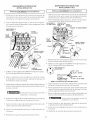
Dimensions D'lnstallation De Secheuse
Ind_pendant Et Sous Le Compteur
l
48.5" _' I'espace fibre ouvrez la porte
(123.19cm)
_
27.25Pour affronter le coffret
27.75Aux boutons clairs
Pipe d'offre de
gaz sur I'arri_re
de I'unit_
,,_5.0" (12.7cm) 2.28"
v Ligne taille centrale
pour arriere, droit,
patti, passage
4.375" (11.12cm) Aux _chappemer
8.875" (14.93cm) Aux _chappemer
(69.22cm)
(70.49cm)
Afimentation _lectrique sur I'arri_re de I'unit_
/
ts lat_raux
ts bas
i i
l
36"
"91.44cm)
i
I"TI', *
i
1_.o !Aux _chappements
d'arri_re et de base
b
27.0"
(68. 58cm)
28.8A la poign_e claire de porte (72.39cm)
Dimensions Empil_es D'lnstallation De Secheuse
9
28.25"Pour affronter le coffret(71.76cm)
28.75" Aux boutons dairs (73.03cm)
29.5"A la poign_e claire de porte (74.93cm)
49'_, I'espace fibre (124.46cm)
ouvrez porte
T
72.00"
(11.12cm) (182.88cm)
4.375"
Echappements
Lat_raux
(104.14cm)
Ligne taille
centrale
pour arriere,
droit, patti,
passage
(34.29cm)
13.5"
Pipe d'offre de
gaz sur I'arriere
de I'unit_
38.25"
(97.16cm)
(68. 58cm)
27.0"
Afimentation
61ectrique sur
I'arri_re de
I'unit_
17

INSTALLATION DANS UNE MAISON MOBILE
1. L'_vacuation d'air de las_cheuse DOITse faire a I'ext_rieu r
de la maison (aI'_xterieur et non pasau-dessousde lamaison
mobile) a I'aide de conduit en m_tal non inflammable,
I'_preuve du feu. Lesconduits en metal doivent avoir 10,16
cm (4 pouces) de diam_tre sansobstructions. Lesconduits
en m_tal rigide sont preferables.
2. Si la conduite d'_vacuation d'air traverse le plancher et un
espaceferm_ situe sous la maison mobile, I'evacuation d'air
DOITseterminer a I'ext_rieurdecet espacefermi, et lasortie
bien fix_e a la structure de la maison mobile.
3. Lorsde I'installation d'une s_cheuseagaz dans une maison
mobile, ilfaut pr_voir un apport d'air ext_rieur. L'espace
pr_voir doit Ctre superieur de deux fois celui du conduit
d'_vacuation de la secheuse.
4. Cette s_cheuse DOIT6tre fix_e au plancher. L'ensemble
d'installation no. 169840 pour maison mobile estdisponible
chez votre distributeur.
5. Ser_f_rer aux pages2 et3 pourde plusamples informations
ur lesexigences de ventilation.
6. L'installation DOlT respecter la norme f_d_rale sur la
construction et la s_curite des maisons mobiles en vigueur
(Manufactured Home Construction & SafetyStandard)(partie
int_grante du r_glement f_d_ra124 CFRPartie 32-80) ou,
Iorsque cette norme nes'applique pas, elle doit respecter la
norme nationale americaine pour les maisons mobiles
(American National Standard for Mobile Homes). Lorsque
I'installation sefait au Canada, elle doit se conformer aux
normes ACNOR Z240.
Las_cheuseest concue conform_ment
la norme ANSI Z 21.5.1 pour un USAGE DOMESTIQUE
seulement.
DEBALLAGE
1. A I'aide desquatre coins de protection de I'emballage (deux
sur chaque c6te), d@oser delicatement la secheusesur son
c6t_ gauche et retirer le morceau de mousse place sous la
s_cheusepour I'exp_dition.
Pour ne pas endommager la s_cheuse, ne
pas prendre prisesurlepanneau de commande pour soulever
ou d_placer la s_cheuse.
REMARQUE :Silas_cheusedoit 6tre install_e sousun com ptoir,
le panneau du dessuspeut 6tre d6monte pour I'installation.
2. Remettre la secheuse a la verticale.
MORCEA U
DE MOUSSE
EMBALLAGE
PORTE RL'VERSIBLE
Instructions pour changer I'ouverture
de la Porte sans Fen@tre :
I. Ouvrez la Porte et enlevez les4 bouchons d'en face oQon trouve
la charni_re. Conservez toutes les pieces pour les utiliser
post_rieurement, a moins qu'on nesp_cifie le contraire. Note •Ayez
des soins en enlevant les bouchons, pour ne pas abimer la peinture
dans le Panneau Frontal.
LES 4 VIS
(UNE DE CHAQUE
2. D_tendez les quatre (4) vis qui tiennent la charni_re au Panneau
Frontal. Pour de meilleurs r_sultats, enlevez seulement une des vis.
Enlevez ensuite les deux restants, entretemps prennez la porte
fermement, pour _viter qu'il tombe et cause desdegats b la charni_re,
le Panneau Frontal ou a la Porte. Apr_s avoir d_tendu lesvis restantes,
enlevez les compl_tement.
3. Placez la Porte, avec le c6t_ de la charni_re vers le has, sur une
serviette ou un matelas _troit, pour _viter qu'il soit doubl_. Enlevez
les quatre (4) vis restantes entre la charni_re et la porte.
4. Enlevez quatre (4) vis dans le c6t_ oppose de la Porte
5. %parez I'anneau int_rieur de I'ext_rieur de la Porte, en plat;ant
un tournevis plat ou un couteau sansbord. Tournez I'anneau int_rieur
180 degr_s et unis a nouveau les deux moiti_s de la porte.
6. Installez quatre (4) vis pour assurer les moiti_s de la Porte, oO il
_tait attach_e la charni_re
7. Installez quatre (4) vis pour assurer lejoint de la charni_re
8. Enlevez le contre de la charni_re et jetez le aux ordures
9. Enlevez le bouchon carr_ et installez-le dans le trou o0 vous avez
enl_ve le contre
10. Installez le contre (raCine qui est fourni dans la bourse de la
Litt_rature) dans le trou tomb_juste, o0 vous avez enl_ve le bouchon
1I. En prenant la porte fermement de la partie superieure, mettez la
pros de la cavit_ et iassurez vous d'aligner le trou sup_rieur de la
charni_re avec le trou superieur du Panneau Frontal. Une fois que
vous avez commence a placer la premiere vis, placez la deuxi_me
dans I'inf_rieur de la charni_re. Quand tousles deux soient serr_s,
installez les autres deux vis.
12. Installez quatre (4) bouchons dans lestrous du Panneau Frontal,
o0 _taient placees les charni_res a I'origine
18

Instructions pour changer I'ouverture de la Porte avec Fen tre
Figure 1
1. Ouvrez la Porte et enlevez les 4 bouchons d'en face oQ on
trouve la chami@e. Conservez toutes les pieces pour les
utiliser post@ieurement, a moins qu'on ne specifie le
contraire. (Figure 1). Note: Ayez des soins en enlevant les
bouchons, pour ne pas abimer la peinture dans le Panneau
Frontal.
Figure 2
Figure 4
5. Enlevez deux (2) vis de la poignee et deux (2) bouchons
de la Porte ; en prennant soin de ne pas doubler la peinture
de la Porte. (Figure 4).
2. Detendez les quatre (4) vis qui tiennent la charniere au
Panneau Frontal. (Figure 2). Pour de meilleurs resultats,
enlevez seulement une des vis. Enlevez ensuite les deux
restants, entretemps prennez la porte fermement, pour eviter
qu'il tombe et cause des degats a la charni@e, le Panneau
Frontal ou a la Porte. Apres avoir detendu les vis restantes,
enlevez les completement.
Figure 3
Figure 5
7. Retirez la poignee loin du joint de la porte.
(Figure 5).
Figure 6
7. Separez la porte externe du joint interne de la porte avec
un couteau ou avec un tournevis plat. (Figure 6).
3. Placez la Porte, avec le cSte de la charniere vers le bas,
sur une serviette ou un matelas etroit, pour eviter qu'il soit
doubl& Enlevez les quatre (4) vis restantes entre la
charniere et la porte. (Figure 3).
4. Enlevez quatre (4) vis du c6te de la Porte, oQ etait
installee la charniere.

Figure 7
11.Montez a nouveau la lentille a I'anneau de transition avec
les trous pour installer la poignee dans le c6te droit de
I'assemblage de la porte. Pour I'ajustement approprie,
assurez que les languettes de retenue dans I'anneau de
transition sont sur la lentille.
8. Enlevez la vis qui fixe la lentille. (Figure 7).
Figure 8
9. en separant plusieurs des languettes de retenue et retirez
la lentille loin de I'anneau de transition. (Figure 8).
Figure 9
Figure 10
Figure 11
12. Installez a nouveau la Porte externe au joint interne de la
porte. (Figure 11)
13. lnstallez quatre (4) vis pour tenir la charniere dans sa
nouvelle situation, en assurant que la charniere ait
I'orientation correcte.
14. tnstallez quatre (4) vis dans les trous oQ etait soumise la
charniere.
15. Enlevez le contre de la charniere et jetez le aux ordures.
16. Enlevez le bouchon carre et installez-le dans le trou oQ
vous avez enleve le contre.
17. lnstallez le contre (m6me qui est fourni dans la bourse
de la Litterature) dans le trou tombe juste, oQ vous avez
enleve le bouchon.
10. Enlevez deux (2) bouchons de I'anneau de transition et
reinstallez au c6te precedent de la poignee. (Figures 9 et 10)
Figure 12
18. Reinstallez de la poignee de la Porte, en faisant passer
les protuberances d'assemblage de cette derniere, a travers
les trous dans le verre et I'annelle et en plagant des vis
travers le panneau interieur de la Porte et en les serrant
dans les protuberances de la poignee. (Figura 12).
19. En prenant la porte fermement de la partie superieure,
mettez la pres de la cavite et iassurez vous d'aligner le trou
superieur de la charniere avec le trou superieur du Panneau
Frontal. Une fois que vous avez commence a placer la
premiere vis, placez la deuxieme dans I'inferieur de la
charniere. Quand tousles deux soient serres, installez les
autres deux vis.
20. lnstallez quatre (4) bouchons dans les trous du Panneau
Frontal, oQetaient placees les charnieres a I'origine
La page charge ...
La page charge ...
La page charge ...
-
 1
1
-
 2
2
-
 3
3
-
 4
4
-
 5
5
-
 6
6
-
 7
7
-
 8
8
-
 9
9
-
 10
10
-
 11
11
-
 12
12
-
 13
13
-
 14
14
-
 15
15
-
 16
16
-
 17
17
-
 18
18
-
 19
19
-
 20
20
-
 21
21
-
 22
22
-
 23
23


Crosley CDEC400FW1 Guide d'installation
- Catégorie
- Sèche-linge électriques
- Taper
- Guide d'installation
- Ce manuel convient également à
dans d''autres langues
Documents connexes
Autres documents
-
GE 134996600B (0711) Manuel utilisateur
-
Frigidaire 137101400 Manuel utilisateur
-
-
Electrolux EIED2CAQSW00 Guide d'installation
-
-
White-Westinghouse FGR641FS1 Guide d'installation
-
-
-
-
Frigidaire AGQ8000FE2 Guide d'installation