Whirlpool UDT555SAFP Guide d'installation
- Taper
- Guide d'installation

UDT555
DISHWASHER SAFETY ................................................................................ 2
INSTALLATION REQUIREMENTS ............................................................... 2
Location Requirements ..............................................................................3
Electrical Requirements.............................................................................. 4
Water Supply Requirements....................................................................... 5
Drain Requirements.................................................................................... 5
INSTALLATION INSTRUCTIONS .................................................................5
Prepare Cabinet Opening—Existing Utility Hookups ................................5
Prepare Cabinet Opening—No Existing Utility Hookups........................... 7
Install Dishwasher.....................................................................................10
Make Electrical Connections—Direct Wire Method ................................12
Make Electrical Connections—Power Supply Cord Method...................12
Connect Dishwasher to Water Supply .....................................................13
Connect Dishwasher to Drain...................................................................13
Attach Dishwasher to Cabinet..................................................................14
Complete Installation................................................................................14
SÉCURITÉ DU LAVE-VAISSELLE.............................................................. 16
EXIGENCES D'INSTALLATION.................................................................. 16
Outillage et composants .......................................................................... 16
Exigences d’emplacement....................................................................... 17
Spécifications électriques ........................................................................ 18
Spécifications de l'alimentation en eau ................................................... 19
Évacuation de l'eau de lavage—Critères à respecter ............................. 19
INSTRUCTIONS D’INSTALLATION........................................................... 19
Préparation de l’espace d’installation entre les placards—Utilisation
des modes de raccordement existants pour canalisations et câblage... 21
Préparation de l’emplacement d’installation entre les placards
lorsque les canalisations et câbles n’ont pas été installés...................... 21
Installation du lave-vaisselle..................................................................... 24
Raccordement au réseau électrique—Câblage direct ............................ 26
Raccordement au réseau électrique—Cordon d’alimentation................ 27
Raccordement à la canalisation d’arrivée d’eau...................................... 28
Raccordement à l’évacuation .................................................................. 28
Immobilisation du lave-vaisselle dans la cavité d’encastrement ............ 28
Achever l’installation................................................................................. 29
IMPORTANT:
Save for local electrical inspector’s use.
Installer: Leave installation instructions with the homeowner.
Homeowner: Keep installation instructions for future reference.
IMPORTANTE:
Guarde para tenerlas a disposición del inspector de electricidad local.
Instalador: Deje las instrucciones de instalación con el propietario.
Propietario: Conserve las instrucciones de instalación para referencia futura.
IMPORTANT :
Conserver pour consultation par l’inspecteur local des installations électriques.
Installateur : Remettre les instructions d’installation au propriétaire.
Propriétaire : Conserver les instructions d’installation pour référence ultérieure.
UNDERCOUNTER DISHWASHER
INSTALLATION INSTRUCTIONS
INSTRUCTIONS D’INSTALLATION DU LAVE-
VAISSELLE ENCASTRÉ
Table of Contents / Table des matières
Models/Modèles
W10703184
1

2
DISHWASHER SAFETY
You need to:
■
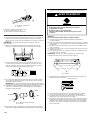
Slowly open dishwasher door while someone grasps the rear
of the dishwasher. Remove shipping materials. Close
dishwasher door. Latch the dishwasher door shut.
■
Observe all governing codes and ordinances.
■
Install this dishwasher as specified in these instructions.
■
Have everything you need to properly install dishwasher.
■
Contact a qualified installer to ensure that dishwasher is
installed to meet all electrical and plumbing national and local
codes and ordinances.
INSTALLATION REQUIREMENTS
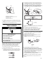
Tools and Parts
Gather the required tools and parts before starting installation.
Read and follow the instructions provided with any tools listed
here.
Tools Needed
Parts Needed
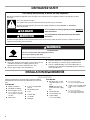
You can be killed or seriously injured if you don't immediately
You
can be killed or seriously injured if you don't
follow
All safety messages will tell you what the potential hazard is, tell you how to reduce the chance of injury, and tell you what can
happen if the instructions are not followed.
Your safety and the safety of others are very important.
We have provided many important safety messages in this manual and on your appliance. Always read and obey all safety
messages.
This is the safety alert symbol.
This symbol alerts you to potential hazards that can kill or hurt you and others.
All safety messages will follow the safety alert symbol and either the word “DANGER” or “WARNING.”
These words mean:
follow instructions.
instructions.
DANGER
WARNING
Tip Over Hazard
Do not use dishwasher until completel
y installed.
Do not push down on open door.
Doing so can result in serious injury or cuts.
WARNING
■
Phillips screwdriver
■
Flat-blade screwdriver
■
Measuring tape or ruler
■
¹⁄₂", ³⁄₄" and 1½" (1.3 mm,
1.9 mm and 3.8 cm) hole
saw bits
■
Shallow pan
■
6" (15.2 cm) adjustable
wrench
■
Small tubing cutter
■
Level
■
Cordless drill
■
¹⁄₈" drill bit
■
Flashlight
■
90º elbow with ³⁄₈" N.P.T.
external threads on one
end
NOTE: The other end
must fit the water supply
line.
■
Thread seal tape
■
3 UL listed wire nuts
■
Copper tubing
(³⁄₈" recommended)
■
1¹⁄₂" to 2" (3.8 cm to
5.1 cm) screw-type clamp
■
Clamp connector (strain relief)
⁷⁄₈" (22.2 cm) diameter
hole
■
1¹⁄₂" to 2" (3.8 cm to
5.1 cm) screw-type clamp
if connecting to waste-tee
to fit

3
Parts Supplied
Check that all parts are included. See separate parts list for
accessories available for your dishwasher.
Location Requirements
IMPORTANT: Observe all governing codes and ordinances.
Failure to meet codes and ordinances could lead to fire or
electrical shock.
Proper installation is your responsibility.
■
Contact a qualified installer to ensure that the dishwasher is
installed to meet all electrical and plumbing national and local
codes and ordinances.
■
Install the dishwasher as specified in these instructions.
■
Have everything you need to properly install dishwasher.
■
Protect dishwasher and water lines leading to dishwasher
against freezing. Damage from freezing is not covered by the
warranty.
■
This dishwasher is manufactured for indoor use only.
■
In
stall and level dishwasher on a floor that will hold the weight,
and in an area suitable for its size and use.
■
Install dishwasher in a location with easy access to water,
electricity and drain.
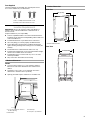
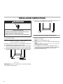
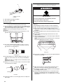
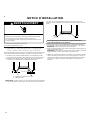
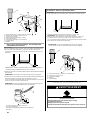
Minimum Clearances
NOTES:
■
Corner locations require 2" (5.1 cm) minimum clearance
between the side of the dishwasher door and the wall or
cabinet.
■
A minimum of 25⁵⁄₈" (65.1 cm) is required in front of the
dishwasher to allow the door to open fully.
■
Opening should be square, and the floor should be level.
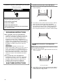
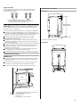
Product Dimensions
Side View
*
* To front of door frame
Rear View
A. #8 x
⁵⁄₈
" Phillips flat-head wood screws
B. Phillips color-matched toekick screws
A. 2" (5.1 cm) minimum clearance
for door opening
B. Dishwasher
C. Countertop
D. 25
⁵⁄₈
" (65.1 cm) minimum
AB
A
B
C
D
24" (61 cm)*
16 5/8"(42.2 cm)
32¹⁄₂" to 34¹⁄₂"
(82.6 to 87.6 cm)
23 5/8"(59.8cm)
■
Fully enclosed on both sides, back, and top.
2 ¹⁄₂" (6.2 cm)

4
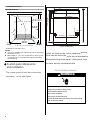
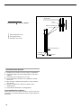
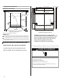
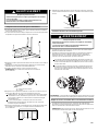
Installation Clearances
Cutout Dimensions
* Underside of countertop to floor
NOTES:
■
Cut holes in shaded area of cabinet walls or floor for plumbing
and electrical service.
■
ADA installation—32¹⁄₂" (82.5 cm) beneath 34" (86.4 cm) high
countertops may be accomplished by adjusting the toekick
and leveling legs.
Electrical Requirements
A. All surfaces free from intrusions
24" (61 cm)
minimum
(83.0 cm to 88.0 cm)
24 (61 cm)
maximum
A
6"
(15.2 cm)
4"
(10.2 cm)
Electrical Shock Hazard
Plug into a grounded 3 prong outlet.
Do not remove ground prong.
Do not use an adapter.
Do not use an extension cord.
Failure to follow these instructions can result in death,
fire, or electrical shock.
WARNING
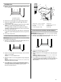
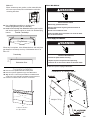
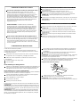
panel
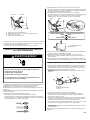
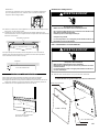
The
should be constructed
according
to the
next Figure.
(Unit: )
inch/cm
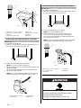
Install the hook on the
panel and
put the
hook into the slot of the
outer door
of dishwasher.
After positioning of the panel , fix the panel
the
outer door by screws and bolts.
onto
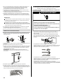
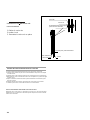
Custom panel dimensions
custom
custom
1.50"(3.8cm)
1.18"(3.0cm)
23.39"(59.4cm)
9.84"(25.0cm)
10"(25.4cm)
0.08"(0.20cm)
0.40"(0.10cm)
22.36"(56.8cm)
2.56"(6.5cm)
6.79"(172.5mm)
19.65"(49.9cm)
26.78"(68.0cm)
21.26"(54.0cm)
0.59"(1.5cm)
1
2
-
H
o
l
e
d
e
e
p
and installation
32 3/4" to 34 1/2"

Contact a qualified electrician.
Ensure that the electrical installation is adequate and in
conformance with all national and local codes and ordinances.
Requirements:
■
120-volt, 60 Hz, AC-only, 15- or 20-amp fused electrical
supply
■
Copper wire only, 2 wire with ground
Recommended:
■
Time-delay fuse or circuit breaker
■
Separate circuit
Direct Wire Connection
■
Use flexible, armored or nonmetalic sheathed, copper wire
with grounding wire that meets the wiring requirements for
your home and local codes and ordinances.
Power Supply Cord Connection
Use Power Supply Cord Kit (Part Number 4317824) marked for
use with dishwashers. Kit contents include:
■
UL listed 16 gauge 3-wire power supply cord with
3 prong grounding plug
■
Neer C-500 ⁷⁄₈" strain relief
■
3 wire connectors
■
Part No. 302797 grommet
Follow the kit instructions for installing the power supply cord.
NOTE: Power supply cord must plug into a mating three prong,
grounded outlet, located in the cabinet next to the dishwasher
opening. Outlet must meet all local codes and ordinances.
IMPORTANT: If you plan to install a garbage disposal, an
additional separate 120-volt, 60 Hz, AC-only, 15- or 20-amp fused
electrical supply is required.
■
For a grounded, cord-connected dishwasher:
The dishwasher must be grounded. In the event of a
malfunction or breakdown, grounding will reduce the
risk of electric shock by providing a path of least
resistance for electric current. The dishwasher is
equipped with a cord having an equipment-grounding
conductor and a grounding plug. The plug must be
plugged into an appropriate outlet that is installed and
grounded in accordance with all local codes and
ordinances.
WARNING:
Improper connection of the
equipment-grounding conductor can result in a risk of
electric shock. Check with a qualified electrician or
service representative if you are in doubt whether the
dishwasher is properly grounded. Do not modify the
plug provided with the dishwasher; if it will not fit the
outlet, have a proper outlet installed by a qualified
electrician.
■
For a permanently connected dishwasher:
The dishwasher must be connected to a grounded
metal, permanent wiring system, or an equipment-
grounding conductor must be run with the circuit
conductors and connected to the equipment-
grounding terminal or lead on the dishwasher.
GROUNDING INSTRUCTIONS
SAVE THESE INSTRUCTIONS
Water Supply Requirements
■
A hot water line with 20-120 psi (138-862 kPa) water pressure.
■
120°F (49°C) water temperature at dishwasher.
■
³⁄₈" O.D. copper tubing with compression fitting or flexible
braided water supply line
.
NOTE: ½" minimum plastic tubing is not recommended.
■
90º elbow with ³⁄₈" N.P.T. external pipe threads on one end.
IMPORTANT: Do not solder within 6" (15.2 cm) from water inlet
valve.
Drain Requirements
■
Use the new drain hose supplied with your dishwasher.
NOTE: If a longer drain hose is required:
■
Use a new drain hose with maximum length of 10 ft (3 m)
that meets all current AHAM/IAPMO test standards
■
Use a new drain hose that is resistant to heat and
detergent
■
Use a new drain hose that fits the 1" (2.5 cm) drain
connector on the dishwasher.
■
Connect drain hose to waste tee or disposal inlet above drain
trap in house plumbing.
■
Connect drain hose to house plumbing 20" (50.8 cm)
minimum above the floor.
NOTE: It is recommended that the drain hose either be looped up
and securely fastened to the underside of the counter, or be
connected to an air gap.
■
Use a drain air gap if the drain hose is connected to house
plumbing lower than 18" (45.7 cm) above the subfloor or floor.
Drain Air Gap
■
Use ½" (1.3 cm) minimum I.D. drain line fittings.
NOTE: Do not connect drain lines from other devices to the
dishwasher drain hose.
5

INSTALLATION INSTRUCTIONS
1. Disconnect power.
2. Turn off water supply.
Prepare Cabinet Opening—
Existing Utility Hookups
Follow the steps in this section if you are installing the dishwasher
in an existing cabinet opening with utility hookups.
1. Check that the water supply line reaches to the front left-hand
side of the opening where the water connection will be made.
2. Check that the direct wire reaches to the front right-hand side
of the opening where the electrical connection will be made.
IMPORTANT: Always use a new drain hose even when installing
a new replacement dishwasher.
3. Drill a 1¹⁄₂" (3.8 cm) diameter hole in the cabinet wall or floor on
the side of the opening closest to the sink.
Connect Drain Hose to Air Gap—Waste Disposal
1. Remove the waste disposal knockout plug. Cut the end of the
drain hose, if needed.
NOTE: Do not cut the ribbed section.
2. Attach the drain hose to the air gap with the large spring-type
clamp.
NOTE: If the drain hose was cut, use 1¹⁄₂" to 2 " (3.8 to 5 cm)
screw-type clamp (not provided).
3. Use a rubber hose connector (not provided) with spring- or
screw-type clamps (not provided) to connect the air gap to the
waste disposal inlet above the drain trap and at least
20" (50.8 cm) above the floor.
A. Water supply line
B. Direct wire
WARNING
Disconnect electrical power at the fuse box or circuit
breaker box before installing dishwasher.
Failure to do so can result in death or electrical shock.
Electrical Shock Hazard
6" (15.2 cm)
A
B
6

Connect Drain Hose to Air Gap—No Waste Disposal
1. Cut the end of the drain hose, if needed.
NOTE: Do not cut the ribbed section.
2. Attach the drain hose to the air gap with the large spring-type
clamp.
NOTE: If the drain hose was cut, use 1¹⁄₂" to 2 " (3.8 to 5 cm)
screw-type clamp (not provided).
3. Use a rubber hose connector (not provided) with spring- or
screw-type clamps (not provided) to connect the air gap to the
waste tee above the drain trap and at least 20" (50.8 cm)
above the floor.
Connect Drain Hose to Waste Disposal—No Air Gap
1. Remove the waste disposal knockout plug.
NOTE: Do not cut the end of the drain hose.
2. Attach the drain hose to the waste disposal inlet with the large
spring-type clamp.
This connection must be before the drain trap and at least
20" (50.8 cm) above the floor.
NOTE: It is recommended that the drain hose be looped up
and securely fastened to the underside of the counter.
Connect Drain Hose—No Waste Disposal or Air Gap
1. Cut the end of the drain hose, if needed.
NOTE: Do not cut the ribbed section.
2. Attach the drain hose to the waste tee with the 1¹⁄₂" to
2" (3.8 cm to 5 cm) screw-type clamp (not provided).
This connection must be before the drain trap and at least
20" (50.8 cm) above the floor.
NOTE: It is recommended that the drain hose be looped up
and securely fastened to the underside of the counter.
A. Drain hose—cut here, if needed
B. Spring- or screw-type clamps
C. Air gap
D. Large spring-type clamp
E. Drain hose
F. Rubber hose connector
G. Disposal inlet
H. Drain trap
A. Drain hose—cut here, if needed
B. Spring- or screw-type clamps
C. Air gap
D. Large spring-type clamp
E. Drain hose
F. Rubber hose connector
G. Waste tee
H. Drain trap
E
D
C
G
H
A
B
F
E
D
C
G
H
A
B
F
A. Large spring-type clamp
B. Drain hose
C. Disposal inlet
D. Drain trap
B
A
C
D
A. Drain hose—cut here, if needed
B. Screw-type clamp
C. Drain hose
D. Drain trap
E. Waste tee
E
D
C
A
B
7

Pr
ep
are Cabinet Opening—No Existing
Utility Hookups
Install Electrical Connection—Direct Wire Method
1. Drill
a ³⁄₄" (1.9 cm) hole in the right-hand cabinet side, the rear
or floor of opening.
2. If the cabinet is wood, sand hole until smooth. If the cabinet is
metal, cover the hole with a grommet (not provided).
3. Route cable from power supply through cabinet hole (cable
Electrical Shock Hazard
Plug into a grounded 3 prong outlet.
Do not remove ground prong.
Do not use an adapter.
Do not use an extension cord.
Failure to follow these instructions can result in death,
fire, or electrical shock.
WARNING
A. Optional locations
B. Preferred locations
■
For a grounded, cord-connected dishwasher:
The dishwasher must be grounded. In the event of a
malfunction or breakdown, grounding will reduce the
risk of electric shock by providing a path of least
resistance for electric current. The dishwasher is
equipped with a cord having an equipment-grounding
conductor and a grounding plug. The plug must be
plugged into an appropriate outlet that is installed and
grounded in accordance with all local codes and
ordinances.
WARNING:
Improper connection of the
equipment-grounding conductor can result in a risk of
electric shock. Check with a qualified electrician or
service representative if you are in doubt whether the
dishwasher is properly grounded. Do not modify the
plug provided with the dishwasher; if it will not fit the
outlet, have a proper outlet installed by a qualified
electrician.
■
For a permanently connected dishwasher:
The dishwasher must be connected to a grounded
metal, permanent wiring system, or an equipment-
grounding conductor must be run with the circuit
conductors and connected to the equipment-
grounding terminal or lead on the dishwasher.
GROUNDING INSTRUCTIONS
SAVE THESE INSTRUCTIONS
B
A
must extend to the right front side of cabinet opening). Tape
cable to the floor 6" in front of unit. This will prohibit cable
from moving when dishwasher is moved into cabinet opening".
Install E
lectrical Connection—Power Supply Cord
Metho
d
NOTE: A mating, 3 prong grounded outlet is required in a cabinet
next to the dishwasher opening.
1. Drill a ³⁄₄" (1.9 cm) hole in the right-hand cabinet side, the rear
or floor of opening.
2. If the cabinet is wood, sand hole until smooth. If the cabinet is
metal, cover the hole with a grommet (Part Number 302797)
included with power supply cord kit.
A. Optional locations
B. Preferred locations
B
A
8

Insta
ll Water Line
1. Drill a ¹⁄₂" (1.3 cm) hole in the left-hand cabinet side, the rear or
floor of opening.
2. Measure the overall length of the copper tubing required.
3. Attach the copper tubing to the water supply line with a
manual shutoff valve.
4. Slowly feed the copper tubing through the hole in the cabinet.
NOTE: The copper tubing will bend and kink easily.
The copper tubing should be far enough into the cabinet
opening to connect it to the dishwasher inlet on the front left-
hand side of the dishwasher.
5. Turn on the water shutoff valve. Run water into a shallow pan
to flush the copper tubing of particles that may clog the inlet
valve.
6. Turn off the shutoff valve.
Connec
t Drain Hose to Air Gap—Waste Disposal
IMPORTANT: Always use a new drain hose even when installing
a new replacement dishwasher.
1. Drill a 1
¹⁄₂
" (3.8 cm) diameter hole in the cabinet wall or floor on
the side of the opening closest to the sink.
2. Remove the waste disposal knockout plug. Cut the end of the
drain hose, if needed.
NOTE: Do not cut the ribbed section.
3. Attach the drain hose to the air gap with the large spring-type
clamp.
NOTE: If the drain hose was cut, use 1¹⁄₂" to 2 " (3.8 to 5 cm)
screw-type clamp (not provided).
4. Use a rubber hose connector (not provided) with spring- or
screw-type clamps (not provided) to connect the air gap to the
waste disposal inlet above the drain trap and at least
20" (50.8 cm) above the floor.
Connect Drain Hose to Air Gap—No Waste Disposal
IMPORTANT: Always use a new drain hose even when installing
a new replacement dishwasher.
1. Drill a 1¹⁄₂" (3.8 cm) diameter hole in the cabinet wall or floor on
the side of the opening closest to the sink.
2. Cut the end of the drain hose, if needed.
NOTE: Do not cut the ribbed section.
3. Attach the drain hose to the air gap with the large spring-type
clamp.
NOTE: If the drain hose was cut, use 1¹⁄₂" to 2 " (3.8 to 5 cm)
screw-type clamp (not provided).
A. Optional locations
B. Preferred locations
B
A
A. Drain hose—cut here, if needed
B. Spring- or screw-type clamps
C. Air gap
D. Large spring-type clamp
E. Drain hose
F. Rubber hose connector
G. Disposal inlet
H. Drain trap
E
D
C
G
H
A
B
F
4. Use a rubber hose connector (not provided) with spring- or
screw-type clamps (not provided) to connect the air gap to the
waste tee above the drain trap and at least 20" (50.8 cm)
above the floor.
9

Connect Drain Hose to Waste Disposal—No Air Gap
IMPORTANT: Always use a new drain hose even when installing
a new replacement dishwasher.
1. Drill a 1¹⁄₂" (3.8 cm) diameter hole in the cabinet wall or floor on
the side of the opening closest to the sink.
2. Remove the waste disposal knockout plug.
NOTE: Do not cut the end of the drain hose.
3. Attach the drain hose to the waste disposal inlet with the large
spring-type clamp.
This connection must be before the drain trap and at least
20" (50.8 cm) above the floor.
NOTE: It is recommended that the drain hose be looped up
and securely fastened to the underside of the counter.
Connect Drain Hose—No Waste Disposal or Air Gap
IMPORTANT: Always use a new drain hose even when installing
a new replacement dishwasher.
1. Drill a 1¹⁄₂" (3.8 cm) diameter hole in the cabinet wall or floor on
the side of the opening closest to the sink.
2. Cut the end of the drain hose, if needed.
NOTE: Do not cut the ribbed section.
3. Attach the drain hose to the waste tee with the 1¹⁄₂" to
2" (3.8 cm to 5 cm) screw-type clamp (not provided).
This connection must be before the drain trap and at least
20" (50.8 cm) above the floor.
NOTE: It is recommended that the drain hose be looped up
and securely fastened to the underside of the counter.
A. Drain hose—cut here, if needed
B. Spring- or screw-type clamps
C. Air gap
D. Large spring-type clamp
E. Drain hose
F. Rubber hose connector
G. Waste tee
H. Drain trap
E
D
C
G
H
A
B
F
A. Large spring-type clamp
B. Drain hose
C. Disposal inlet
D. Drain trap
B
A
C
D
A. Drain hose—cut here, if needed
B. Screw-type clamp
C. Drain hose
D. Drain trap
E. Waste tee
E
D
C
A
B
Install Dishwasher
WARNING
Tip Over Hazard
Do not use dishwasher until completely installed.
Do not push down on open door.
Doing so can result in serious injury or cuts.
10

11
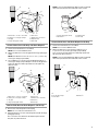
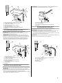
Prepare Dishwasher for Installation
1. Using 2 or more people, place the dishwasher on its back on a
piece of cardboard.
2. Using a Phillips screwdriver, remove the 4 screws attaching
the toekick panel and lower
panel to the dishwasher.
3. Remove both panels and set aside on a protected surface.
4. Apply thread seal tape to 90º elbow fitting and connect fitting
to water inlet valve.
5. Tighten elbow until snug.
NOTE: Elbow should face to the rear of the dishwasher.
terminal box cover.
■
Direct Wire—Install a U.L. listed/CSA certified clamp
connector to the terminal box. If using conduit, use a U.L.
listed/CSA certified conduit connector.
■
Power Supply Cord—Install a power supply cord kit that is
U.L. listed and marked for use with dishwashers (Part
Number 4317824).
7. Measure the shortest opening height between the underside
of the countertop and the floor where the dishwasher will be
installed.
8. Extend leveling legs out from the dishwasher base, ¹⁄₄" less
than the shortest opening height.
WARNING
Excessive Weight Hazard
Use two or more people to move and install
dishwasher.
Failure to do so can result in back or other injury.
A. Screws
A. Water inlet valve
B. Elbow
A. Leveling leg
A
A
B
A
6. Remove top screw and slide cover to the right to remove
Check Door Spring Tension
1. Using 2 or more people, place the dishwasher upright in front
of cabinet opening.
2. With one person holding the dishwasher to avoid tipping,
open and close the dishwasher door a few times. If the door
closes too quickly or falls open under its own weight, adjust
the tension.
■
If the door closes too quickly, decrease the spring tension
by pulling the spring adjustment pin out of its hole and
reinsert it into the next lower hole toward the back of the
dishwasher.
■
If the door falls open, increase the spring tension by
pulling the spring adjustment pin out of its hole and
reinserting it into the next higher hole toward the top
of the dishwasher.
NOTE: The spring adjustment pins should be in the same holes
on both the left-hand and right-hand sides of the dishwasher.
Mo
ve Dishwasher into Cabinet Opening
1. Using 2 or more people, grasp the sides of the dishwasher at
the edges of the door panel and move dishwasher close to the
cabinet opening.
NOTE: Do not push on the front of the panel or on the console
to avoid bending or denting them.
Excessive Weight Hazard
Use two or more people to move and install
dishwasher.
Failure to do so can result in back or other injury.
ARNING
W

12
2. If direct wired, check that the power supply wire is on the
right-hand side at the front of the cabinet opening.
If using a power supply cord, insert the power supply cord
through the hole cut in the cabinet wall.
3. Check that the water supply line is on the left-hand side of the
cabinet opening.
4. Check that the drain hose is near the center and insert the drain
hose through the hole in the cabinet .
5. Slowly move the dishwasher into place inside the cabinet
opening with the front corners of the dishwasher door flush
with the cabinet doors.
NOTES:
■
Do not kink or pinch the copper tubing, drain hose, power
supply cord or the direct wire between the dishwasher and
the cabinet.
■
Do not remove the insulation blanket from dishwasher to
allow the dishwasher to fit easier into the cabinet opening.
The insulation blanket reduces the sound level when the
dishwasher is operating.
6. If needed, support the front of the dishwasher by raising,
lowering or shimming the front legs.
7. Remove cardboard from beneath the dishwasher.
Level the Dishwasher
1. Align the front of the dishwasher door panel with the cabinet
doors by adjusting the front legs using the 6" adjustable
wrench.
2. Check that the leveling legs are firmly against the floor.
3. Close and latch the dishwasher door.
4. Place a level against the front panel above the leg to check
that the dishwasher is plumb. If needed, adjust the leveling leg
or add shims until the dishwasher is plumb.
NOTE: Shims must be securely attached to the floor to avoid
their movement during dishwasher operation.
5. Repeat for the other side of the dishwasher.
6. Place the level against the top front opening of the tub. Check
that the dishwasher is level from side to side. If the
dishwasher is not level, adjust the front legs up or down until
the dishwasher is level.
Make Electrical Connections—
Direct Wire Method
Review “Electrical Requirements” before continuing.
1. Route the direct wire so that it does not touch the dishwasher
motor or lower part of the dishwasher tub.
2. Pull cable through UL listed / CSA approved strain relief in
3. Using twist-on connectors sized to connect direct wire to
16-gauge dishwasher wire, connect the white wire from the
power supply to the white wire on the terminal box.
4. Using twist-on connectors sized to connect direct wire to
16-gauge dishwasher wire, connect the black wire from the
power supply to the black wire on the terminal box.
5. Using twist-on connectors sized to connect direct wire to
16-gauge dishwasher wire, connect the ground wires from the
power supply to the green ground dishwasher wire.
WARNING
Electrical Shock Hazard
Electrically ground dishwasher.
Connect ground wire to green ground connector in
terminal box.
Do not use an extension cord.
Failure to follow these instructions can result in death,
fire, or electrical shock.
erminal box. Strain relief is not provided with dishwasher.
Owner must purchase a 7/8" screw-in type strain relief.

Use UL listed power supply cord kit (part number 4317824).
54"
(1
37.2 cm) minimum and 64" (162.6 cm) maximum.
13
6. Tighten the clamp connector or conduit connector screws.
7. Reinstall the terminal box cover with the wires inside terminal
box.
8. Check that no wires are pinched by the cover.
Ma
ke Electrical Connections—Power
Supply Cord Method
Th
e power supply cored and connections must comply with the
National Electrical Code, Section 422 and/or local codes and
ordinances. Recommended power supply cord length is
1. Remove the terminal box cover.
2. Using twist-on connectors sized to connect direct wire to
16-gauge dishwasher wire, connect the white wire from the
power supply cord to the white wire on the terminal box.
Electrical Shock Hazard
Plug into a grounded 3 prong outlet.
Do not remove ground prong.
Do not use an adapter.
Do not use an extension cord.
Failure to follow these instructions can result in death,
fire, or electrical shock.
W
ARNING
A. Wh
ite wire to white wire
B.Ground wires to green ground connector
C. Grounding screw
D. Black wire to black wire
3. Us
ing twist-on connectors sized to connect direct wire to
16-gauge dishwasher wire, connect the black wire from the
power supply cord to the black wire on the terminal box.
4. Using twist-on connectors sized to connect direct wire to
16-gauge dishwasher wire, connect the ground wire from the
power supply cord to the green ground dishwasher wire.
5. Reinstall the terminal box cover with the wires inside terminal
box.
6. Check that no wires are pinched by the cover.
7. Plug power supply cord into a grounded 3 prong outlet.
8. Check that the power supply cord does not touch the
dishwasher motor or lower part of dishwasher tub.
Co
nnect Dishwasher to Water Supply
1. Rou
te the water supply line so that it does not touch the
dishwasher base, frame or motor.
2. Slide the nut onto the copper tubing about 1" (2.5 cm).
3. Slide the ferrule onto the tubing.
NOTE: Do not position ferrule on the end of the tubing.
4. Push the tubing into the elbow as far as it will go.
5. Slide the nut and ferrule forward and start the nut onto the
elbow threads. Avoid bending or kinking the copper tubing.
6. With the copper tubing pushed into the compression fitting as
far as it will go, use a wrench and tighten the compression
fitting nut to elbow on water inlet valve.
NOTE: Do not use Teflon
®
tape with
compression fittings.
A. El
bow
B. Ferrule
C. Nut
A
B
C
®T
eflon is a registered trademark of E.I. Dupont de Nemours and
Company.
black
white
ground
Terminal bo
x wire:
white
blac
k
ground wire
Power supply wire:
white
blac
k
ground wire
terminal
bo
x cover
7. With flexible braided connections, secure nut to elbow using
5/8" open ended wrench or adjustable wrench.
black
white
ground
A.
B.
D.
C

14
8. Place paper towel under the elbow.
9. Turn on the water supply.
10. Check for leaks.
Connect Dishwasher to Drain
11. Route the drain hose so that it does not touch the dishwasher
motor, door springs, water line, cabinet, flooring or the edge of
the hole where it passes through the cabinet.
NOTE: Do not remove the drain loop from the side of the
dishwasher.
12. Place the shallow pan under the end of the drain hose. The
pan will collect any water in the drain hose.
13. Cut on the molded end of the drain hose to fit 1" (2.5 cm),
³⁄₄" (1.9 cm) or ⁵⁄₈" (1.6 cm) diameter connections on the air
gap, waste tee or waste disposal.
14. If a longer drain hose is required, add up to 42" (107 cm) of
length for a total of 10 ft (3 m) to the factory-installed drain
hose.
NOTE: Total drain hose length must not exceed 10 ft (3 m) for
proper drain operation.
15. Using ⁵⁄₈" or ⁷⁄₈" I.D. hose and a coupler, connect the two drain
hose ends with hose clamps.
16. Connect the drain hose to the air gap, waste tee or disposal
with clamps.
A. Water inlet valve
B. Elbow
A. Drain hose
A. Cutting lines
A. Hose clamps
B. Coupler
A
B
A
A
A
A
B
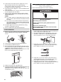
The dishwasher must be secured to wood countertop.
Method 1
Attach Dishwasher to Cabinet
17. Open the dishwasher door and remove the lower dish rack.
18. Place a towel over the pump assembly and spray arm of
dishwasher to keep screws from falling into pump area during
installation.
19. Check that the dishwasher is level and centered side to side in
the opening.
20. Check that the tub flange aligns with the front face of the
cabinet frame.
21. Attach the dishwasher to the countertop using the 2 brackets
on top of the dishwasher.
NOTE: The dishwasher must be attached to the countertop to
keep it from tipping when the door is opened.
22. Insert 2 #8 x ⁵⁄₈" Phillips flat-head screws through the brackets
and into the countertop.
23. Open the door about 3" (7.6 cm) and check that the space
between the inner door and tub is equal on both sides.
24. If spacing is not equal, loosen the bracket screws and shift the
tub. Retighten bracket screws.
25. Check that the top of the door does not contact the screws,
brackets or countertop. If it does, the dishwasher must be
lowered and leveled again. See “Level Dishwasher” in “Install
Dishwasher.”
A. Brackets
WARNING
Tip Over Hazard
Do not use dishwasher until completely installed.
Do not push down on open door.
Doing so can result in serious injury or cuts.
A
Wood countertop

27.
mounting brackets.
will not accept screws,secure dishwasher with side-
When countertops are granite or other materials that
``Method 2
15
remove plug buttons (one on each side).
Install screws through the dishwasher side mount bracket
and into the adjacent cabinet on each side. Reinstall plug
buttons.
When step is complete, close dishwasher door and verify that
gap between countertop and top of dishwasher door is at
least 1/2".
Countertop
Scr
ews
Plug Buttons
Granite Counter
top
½'’
min.
Dishwasher Door
26.
Use a flat-blade screwdriver or prying tool to
Complete Installation
28. Place the lower panel behind the toekick panel.
29. Place the 2 panels against the legs of the dishwasher.
30. Align the slots on the inner panel with the toekick bracket
screw holes. The lower panel should be touching the floor.
31. Insert the 4 toekick screws into the 4 screw holes.
A. Top 4 screw holes
B. 2-piece toekick
A
B
Direct Wire Method
Electrical Shock Hazard
Electricall
y ground dishwasher.
Connect ground wire to green ground connector in
terminal box.
Do not use an extension cord.
Failure to follow these instructions can result in death,
fire, or electrical shock.
Power Supply Cord Method
32. Reconnect power or plug in dishwasher.
WARNING
Electrical Shock Hazard
Disconnect power before servicing.
Replace all parts and panels before operating.
Failure to do so can result in death or electrical shock.
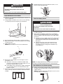
WARNING
Installation of
panel
custom
Weight < 3.5 kg

16
Check Dishwasher Operation
1. Read the User Instructions that came with your dishwasher.
2. Check that all parts have been installed and no steps were
skipped.
3. Check that you have all the tools you used.
4. Start the dishwasher and allow it to complete the shortest
wash cycle.
5. After 2 minutes, unlatch the door. Wait 5 seconds, and then
open the door.
6. Check to see that there is water in the bottom of the
dishwasher tub.
7. Check that the dishwasher is working properly.
If you need Assistance or Service
Please reference the “Assistance or Service” section of your User
Instructions or contact the dealer from whom you purchased your
dishwasher.
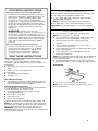
Installation of
1. Take away the cover
2. Pin up the screw
3. Get back the cover
Furniture door
Hook for aesthetic door
Outer door of
dishwasher
Spacer for furniture door
Cover
4X18 screw
panel
custom

NOTES
17

UDT555
DISHWASHER SAFETY ................................................................................ 2
INSTALLATION REQUIREMENTS ............................................................... 2
Location Requirements ..............................................................................3
Electrical Requirements.............................................................................. 4
Water Supply Requirements....................................................................... 5
Drain Requirements.................................................................................... 5
INSTALLATION INSTRUCTIONS .................................................................5
Prepare Cabinet Opening—Existing Utility Hookups ................................5
Prepare Cabinet Opening—No Existing Utility Hookups........................... 7
Install Dishwasher.....................................................................................10
Make Electrical Connections—Direct Wire Method ................................12
Make Electrical Connections—Power Supply Cord Method...................12
Connect Dishwasher to Water Supply .....................................................13
Connect Dishwasher to Drain...................................................................13
Attach Dishwasher to Cabinet..................................................................14
Complete Installation................................................................................14
SÉCURITÉ DU LAVE-VAISSELLE.............................................................. 16
EXIGENCES D'INSTALLATION.................................................................. 16
Outillage et composants .......................................................................... 16
Exigences d’emplacement....................................................................... 17
Spécifications électriques ........................................................................ 18
Spécifications de l'alimentation en eau ................................................... 19
Évacuation de l'eau de lavage—Critères à respecter ............................. 19
INSTRUCTIONS D’INSTALLATION........................................................... 19
Préparation de l’espace d’installation entre les placards—Utilisation
des modes de raccordement existants pour canalisations et câblage... 21
Préparation de l’emplacement d’installation entre les placards
lorsque les canalisations et câbles n’ont pas été installés...................... 21
Installation du lave-vaisselle..................................................................... 24
Raccordement au réseau électrique—Câblage direct ............................ 26
Raccordement au réseau électrique—Cordon d’alimentation................ 27
Raccordement à la canalisation d’arrivée d’eau...................................... 28
Raccordement à l’évacuation .................................................................. 28
Immobilisation du lave-vaisselle dans la cavité d’encastrement ............ 28
Achever l’installation................................................................................. 29
IMPORTANT:
Save for local electrical inspector’s use.
Installer: Leave installation instructions with the homeowner.
Homeowner: Keep installation instructions for future reference.
IMPORTANTE:
Guarde para tenerlas a disposición del inspector de electricidad local.
Instalador: Deje las instrucciones de instalación con el propietario.
Propietario: Conserve las instrucciones de instalación para referencia futura.
IMPORTANT :
Conserver pour consultation par l’inspecteur local des installations électriques.
Installateur : Remettre les instructions d’installation au propriétaire.
Propriétaire : Conserver les instructions d’installation pour référence ultérieure.
UNDERCOUNTER DISHWASHER
INSTALLATION INSTRUCTIONS
INSTRUCTIONS D’INSTALLATION DU LAVE-
VAISSELLE ENCASTRÉ
Table of Contents / Table des matières
Models/Modèles
W10703184
1

SÉCURITÉ DU LAVE-VAISSELLE
Vot re sécurité et celle des autres est t rès importante.
Dans ce manue let sur v otre a ppare il, nous fourn is sonsde no mbreux messages impor tants des écurité. Lisez e tr esp ectez toujour s
tous les messagesdesécurité.
Ceci est le symbo led' a lerte de sécurité.
Ces ymbol e met en garde cont reles r isque sp otentiels qui pe uvent vous tuer ou v ous blesse r,vous ou d'a utres
pers onnes .
To us lesm essages de s écu rit ésu ivent les ymbol ed'alerte de sécurité ou lem ot « DAN GER » ou
« AVERTISSEMENT».Cesmotssignifient:
DANGER
AVERTISSEMENT
Vouspourriezêtretué ougravementblessési vousnerespectez
pas im média tement les consignes.
Vouspourriezêtretué ougravementblessési vousnerespectez
pas lesco nsigne s.
To us les m essages de s écuri téindiq uen tle risque potent iel,vous d ise nt c omment réduire la proba bilit édeble ssure e tc equ ipeu t
arriv er si le scons ignes ne sont pas respec tées.
AVERTISSEMENT
Risque de b asculem ent
N 'utilis ezpas lel ave- va isselle ta ntqu'il n'est pas complèt eme nt insta llé.
N'appu yez passur l aporte ouverte.
Celapourrait entraîner desblessures graves ou descoupures.
Vous devez :
Ou vrirdo ucem entla p orte d u lave -vaisse llep e ndan t que
quelqu'unsaisitl'arrièredu lave-vaisselle.Retirerlesmatériaux
d'e xpédi tion. F e rmer la port e du la ve-vai ssel le. Verrou iller l a
po rtedu l ave-v aissell e.
Re spe cter tous lesc odes et r èglem en ts en vig ueur.
Installerc e l ave-vaissel leconf ormé ment à ces c o nsi gnes.
Dispo ser de tout cedont vous avez b e soin pour i nstalle r
correctementlelave-vaisselle.
Contacter u ninsta llateur qualifi épou rvous assur erq ue le
lave-vaissellesoitinstallécon formémentà tous lescodes
etrèg leme ntsn at ionaux et loc aux en matière d'électr icité
et de plomb erie.
CONFIGURATION REQUISE POURL'INSTALLATION
Outils et piè ces
Rassem ble zle spi èces et outils r equis av antde commen cer
l'install a tion. Lisez et respect ezles consignes four nies a vec
tout outil indiq ué i ci.
Outi ls nécessa ires
Pièc esn éce ssai res
Coude à 90 ° a vecfi letages
externes N.P. Tde ³/ 8 po à
une extrémité
Collie r de s er rage à vis d e 1¹/2
poà2po(3,8cmà5,1cm)
Connec teur de co llier ( s erre-c âble)
Tournevis Phillips
Tournevis à lame plate
Ruban ou r èg le à m esure r
Forets de scie àtrou sde ¹/2
po,³/4poet1½po(1,3mm,
1,9 mm et 3,8 cm)
Assiettepeuprofonde
Clé réglable de 6 po (15,2c m)
Petit c oupe-tu be
Niveau
Perceusesansfil
Mè ch e de ¹/8 po
Lampe torc he
REM ARQ UE : L'autre extrémité
doit co rrespo ndr e à la con duite
d'alimentationeneau.
Ruban d'étan ch éité pour filetag e
3écr ousde câble homo logu é sUL
Collierde serrageà visde1¹/2
poà2po(3,8cmà5,1cm)en
cas de raccor demen ta u téde
vidage
Tube e nc uivre
(³/8po recommandé)
pour c orresp ondre a utro u de
diamètr e7/ 8 po(22 ,2cm)
2

Pièc es fourni es
V ér ifiez que toutes les pi è ces so nt inc luses. Report ez- vousà
la liste sép aréede s pièces pour les acc essoi resdis ponib les
pourvotre lave-vaisselle.
Dim ens ions du pr od uit
Vuelatérale
A.VisàboisàtêteplatePhillipsn°8x5/8po
B.Vis de plin thePhi llips , àe mp reinte crucif orme,
dec ouleu rass ortie, d e24 po (61 cm)*
Configuration requise pour l'emplacement
IMPORTANT : Resp ect ez tous le scodes et rè gleme nts env igueur.
Le non- respe ctd es codes et des rè glements peut engend rerun
incendi e ou u nc hoc électri que.
Il est d e votre respo nsabilité d'effectue rune i nstall ation appropr iée.
Contactez u nins tallate urqua lifié p ourvo us ass urer q ue le la ve-
vais selles oiti nst all é c onformémen tà tou s les co des et règle ments
nationaux etlocauxen matièred'électricitéetde plomberie.
Inst allez le lave-v aisse lle con formé ment à ces consig nes.
Dispo sez deto ut cedo nt vou s avez besoin pour instal ler
corr ectement le lave-v aissel le.
Protégez l e lave -vaiss elle et l esc onduite s d'eau allan tau la ve -
vaissellec ontre legel. Les dégâtscauséspar le gelne sont pas
cou verts p arla gar an ti e.
Cela ve-vai ssell e est fab riqu é pour unusa gein térieur uniqu ement.
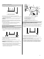
16-5/8 po (42,2 cm)
2 ¹/2 po (6,2c m)
Inst allez et mettez àni veau le lave-v aisse lle su r unpla ncher qui
en supporterale poids,dansunespaceconvenablepourses
dim ensi ons etso n utili sation .
Installez le lave-v aisselle da ns un emplac emen t dispo santd 'un
accès facil eà l'e au, à l 'électric ité et à la v idange .
Complète men t é tanche des deux c ôtés, à l'arrièr eet a u som met.
23-5/8 po(59,8 cm)
D éga g ement s m in im a ux
REM ARQ UES :
Les empla cements en coin n éc essi t ent u n déga geme nt mini mal
de2po(5,1cm)entrelecôtédelaportedulave-vaisselleetlae
mur o u l'arm oire.
Un m inim umde 255/8 po (65, 1cm) est r equis à l'avant d ulav e-
va isselle pour perme ttre l'o uvertu re com plète de la porte.
L'o uvertur e doit ê tre c arrée et lepl ancher doit ê treà n iveau.
A. U ndé gagement de 2 po (5,1 cm ) mini mum
pour l'ouve rturede la po rte.
B. La ve- vaissel le
C.Comptoir
D .255/8 po (65,1 cm) minimu m
Vue arrière
* À l'ava nt duc adred e lap orte
32¹/2 poà 34¹/2 po
(82,6à 87,6cm)
24 p o (6 1 cm ) m ax i mum
3
La page est en cours de chargement...
La page est en cours de chargement...
La page est en cours de chargement...
La page est en cours de chargement...
La page est en cours de chargement...
La page est en cours de chargement...
La page est en cours de chargement...
La page est en cours de chargement...
La page est en cours de chargement...
La page est en cours de chargement...
La page est en cours de chargement...
La page est en cours de chargement...
La page est en cours de chargement...
La page est en cours de chargement...
-
 1
1
-
 2
2
-
 3
3
-
 4
4
-
 5
5
-
 6
6
-
 7
7
-
 8
8
-
 9
9
-
 10
10
-
 11
11
-
 12
12
-
 13
13
-
 14
14
-
 15
15
-
 16
16
-
 17
17
-
 18
18
-
 19
19
-
 20
20
-
 21
21
-
 22
22
-
 23
23
-
 24
24
-
 25
25
-
 26
26
-
 27
27
-
 28
28
-
 29
29
-
 30
30
-
 31
31
-
 32
32
-
 33
33
-
 34
34


Whirlpool UDT555SAFP Guide d'installation
- Taper
- Guide d'installation
dans d''autres langues
Documents connexes
-
Whirlpool GU3100XTVB Manuel utilisateur
-
Whirlpool WDF550SAFW Le manuel du propriétaire
-
Whirlpool WDF550SAFS0 Guide d'installation
-
Whirlpool GU3200XTVY1 Guide d'installation
-
Inglis TUD8750SD1 Guide d'installation
-
-