Hilti DD 130 Mode d'emploi
- Catégorie
- Fournitures pour aspirateur
- Taper
- Mode d'emploi

DD 130
Operating instructions en
Mode d’emploi fr
zh
ja
ko
cn
ar
Printed: 08.07.2013 | Doc-Nr: PUB / 5069522 / 000 / 01

1
Printed: 08.07.2013 | Doc-Nr: PUB / 5069522 / 000 / 01

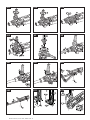
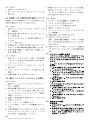
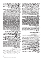
6.1.1
6.1.3
6.4.1
6.6.2
6.1.2
6.2
6.5.1
6.7.1
6.1.2
6.3
6.6.1
6.7.2
Printed: 08.07.2013 | Doc-Nr: PUB / 5069522 / 000 / 01

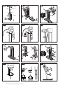
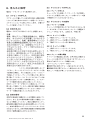
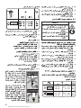
6.7.3
6.10
7.2.1
6.8
6.11
7.2.2
6.9
6.12
7.3
6.9.1
®
DD130
6.9.2 6.9.3
Printed: 08.07.2013 | Doc-Nr: PUB / 5069522 / 000 / 01

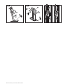
7.4 7.5 8.5.1.1 8.5.1.2
Printed: 08.07.2013 | Doc-Nr: PUB / 5069522 / 000 / 01

1
It is essential that the operating
instructions are read before the
tool is operated for the first time.
Always keep these operating
instructions together with the tool.
Ensure that the operating instruc-
tions are with the tool when it is
given to other persons.
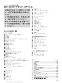
Contents Page
1. General information 2
2. Description 2
3. Tools and accessories 3
4. Technical data 3
5. Safety rules 5
6. Before use 7
7. Operation 10
8. Care and maintenance 12
9. Troubleshooting 13
10. Disposal 14
11. Manufacturer's warranty – tools 14
12. Declaration of conformity (original) 14
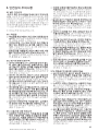
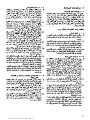
ORIGINAL OPERATING INSTRUCTIONS
DD130 diamond core drilling machine
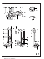
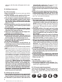
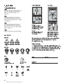
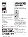
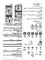
Parts of the DD130
Core drilling machine
Water swivel / extraction head
Water flow indicator
Level indicator
Screwdriver (side handle)
Side handle
Water flow regulator
Water hose connector
Gear selector
Gearing section
Motor
On / off switch
Grip
Overload indicator
Supply cord with PRCD
Rating plate
Interface plate
Screw plugs (water swivel / extraction head)
Cover (water swivel / extraction head)
Extraction connector
Water swivel lock
Locking ring (water swivel / extraction head)
Chuck
Drill stand
Grip
Chain
Columns
Hex. wrench
Carriage
Release lever
Specification plate
Vacuum release valve
Vacuum hose connector
Vacuum pad
Baseplate
Chain arrestor
Hand wheel
On / off switch lock
Pressure gauge
Level indicator
Adjusting lever
Levelling screws
Hole centre indicator
Locating lugs
Depth gauge
Locking mechanism
Mounting pins
Chain tensioner
Water collector for hand-held use
Securing knob
Clamping screw
Depth gauge
Water collector cup
Centring ring
Centring ring adaptor
Seal
Mounting plate
Water collector for use with the drill stand
Holder
Water collector cup
Seal
햲
햳
햴
햵
햶
햷
햸
햹
햺
햻
햽
햾
햿
헀
헁
헂
헃
헄
헅
헆
쎻
21
쎻
22
쎻
23
쎻
24
쎻
25
쎻
26
쎻
27
쎻
28
쎻
29
쎻
30
쎻
3
1
쎻
32
쎻
33
쎻
3
4
쎻
35
쎻
36
쎻
3
7
쎻
38
쎻
39
쎻
40
쎻
41
쎻
42
쎻
43
쎻
44
쎻
45
쎻
46
쎻
47
쎻
48
쎻
49
쎻
50
쎻
51
쎻
52
쎻
53
쎻
54
쎻
55
쎻
56
쎻
57
Printed: 08.07.2013 | Doc-Nr: PUB / 5069522 / 000 / 01

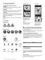
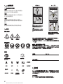
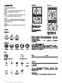
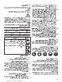
2
General
warning
Warning:
electricity
Warning: hot
surface
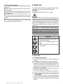
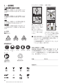
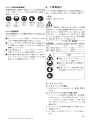
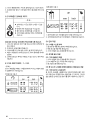
Obligation signs
Symbols
On the drill stand On the tool
Wear eye
protection
Wear a safety
helmet
Wear ear
protection
Wear safety
gloves
Wear safety
boots
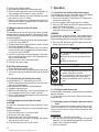
1. General information
1.1 Safety notices and their meaning
-DANGER-
Draws attention to imminent danger that will lead to seri-
ous bodily injury or fatality.
-WARNING-
Draws attention to a potentially dangerous situation that
could lead to serious personal injury or fatality.
-CAUTION-
Draws attention to a potentially dangerous situation that
could lead to slight personal injury or damage to the
equipment or other property.
-NOTE-
Draws attention to an instruction or other useful infor-
mation.
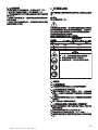
1.2 Pictograms
Warning signs
VACUUM
V
ACUUM
Top
An additional means of secur-
ing the drill stand must be
employed when used for hori-
zontal drilling with vacuum
attachment.
Bottom
The drill stand must be fas-
tened by means of an anchor
or quick-release brace when
used for overhead drilling.
Use of the water collector
system in conjunction with a
wet-type vacuum cleaner is
mandatory when working
overhead on ceilings.
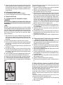
These numbers refer to the corresponding illustra-
tions. The illustrations can be found on the fold-out cov-
er pages. Keep these pages open while studying the
operating instructions.
In these operating instructions, the DD 130 core drilling
machine is referred to as "the tool".
Location of identification data on the tool
The type designation and serial number can be found
on the rating plate on the tool. Make a note of this data
in your operating instructions and always refer to it when
making an enquiry to your Hilti representative or ser-
vice department.
Type: DD130
Serial no.:
Read the operating
instructions before use.
Return waste material
for recycling.
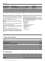
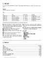
2. Description
The DD 130 is an electrically powered diamond core
drilling machine designed for hand-held use or for mount-
ing on a drill stand. It is suitable for wet or dry core
drilling.
Use as intended
The DD 130 is designed for drilling through holes and
blind holes in mineral materials.
V
~
n
o
∅∅
HzW
/min
A
rpm
Amps Volts Watts Hertz Revolutions
per minute
Revolutions
per minute
Alternating
current
Nominal
speed under
no load
Diameter
Printed: 08.07.2013 | Doc-Nr: PUB / 5069522 / 000 / 01

3
● Horizontal drilling with vacuum attachment is per-
missible only when an additional means of securing the
drill stand is employed. The drill stand may be used for
overhead drilling only when fastened by an anchor or
by means of a quick-release brace.
● Drilling into materials containing asbestos is not per-
missible.
● Changes or modifications to the tool are not permis-
sible.
● To avoid the risk of injury, use only original Hilti acces-
sories and additional equipment.
● Observe the information printed in the operating
instructions concerning operation, care and mainte-
nance.
● The tool is intended for professional use.
● The tool may be operated, serviced and repaired only
by authorised, trained personnel. This personnel must
be informed of any special hazards that may be encoun-
tered.
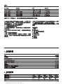
3. Tools and accessories
Designation Item no.
Vacuum pump 47034
Quick-release brace 9870
Water collector system for hand-held use 370462
Water collector system for drill stand use 370460
Drill stand 370461
Wheel assembly 232228
DD-CS M12S-SM clamping spindle 251830
DD-CN SML clamping nut 251834
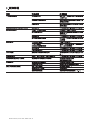
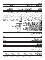
Applications:
W
ith / without drill stand Core bit diameter Drilling direction
Hand-held / dry With dust extraction, 12–162 mm dia. All directions
Hand-held / wet Without water collection system, 12– 62 mm dia. Not upwards
Hand-held / wet With water collection system, 12– 62 mm dia. All directions
Drill stand / wet Without water collection system, 12–152 mm dia. Not upwards
Drill stand / wet With water collection system 12–132 mm dia. All directions
When drilling in an upwards direction, a wet-type vacuum cleaner must be connected to the water collection system.
● The tool and its accessories may, nevertheless, pre-
sent hazards when used incorrectly by untrained per-
sonnel or when used not as directed.
● The machine may be operated only when connect-
ed to an adequately-rated electric supply equipped
with an earth (ground) conductor.
Items supplied:
– Power tool
– Side handle
– Hilti toolbox or cardboard box
– Operating instructions
– Cleaning cloth
– Wrench SW 19
– Grease
– Protective glasses
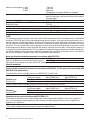
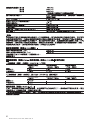
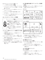
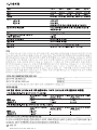
4. Technical data
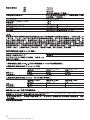
Nominal voltage: * 110 V 120 V 220 V 230 V 240 V
Nominal power: 1700 W 1800 W 1900 W 1900 W 1900 W
Nominal current: * 16 A 15 A 9.1 A 8.7 A 8.3 A
Frequency 50/60 Hz 50/60 Hz 50/60Hz 50/60Hz 50/60Hz
Printed: 08.07.2013 | Doc-Nr: PUB / 5069522 / 000 / 01

4
Nominal no-load speed 1
st
gear 780 /min
2
nd
gear 1400 /min
3
rd
gear 2600 /min
(Change gear only when rotation has stopped.)
Max. permissible water supply pressure: 6 bar (In the event of higher water pressure, a
pressure reduction valve must be fitted at the building
site connection.)
Dimensions (L×W×H): 515×114×170 mm
Weight as per EPTA-Procedure 01/2003: 7.3 kg
Weight drill stand 13.1 kg
Radio and television interference suppression as per EN 55014-1
Interference immunity: as per EN 55014-2
Protection class as per EN 60745 and IEC 60745: Protection class I (earthed)
Drilling depth: max. 430 mm (730 mm with extension)
-NOTE-
The vibration emission level given in this information sheet has been measured in accordance with a standardised
test given in EN 60745 and may be used to compare one tool with another. It may be used for a preliminary assess-
ment of exposure. The declared vibration emission level represents the main applications of the tool. However if
the tool is used for different applications, with different accessories or poorly maintained, the vibration emission
may differ. This may significantly increase the exposure level over the total working period. An estimation of the
level of exposure to vibration should also take into account the times when the tool is switched off or when it is
running but not actually doing the job. This may significantly reduce the exposure level over the total working peri-
od. Identify additional safety measures to protect the operator from the effects of vibration such as: maintain the
tool and the accessories, keep the hands warm, organisation of work patterns.
Noise and vibration information (measured in accordance with EN 60745):
Typical A-weighted noise power level (LwA): 100 dB (A)
Typical A-weighted noise emission pressure level (LpA): 89 dB (A)
For the given sound power level as per EN 60745, the tolerance is 3 dB.
Wear ear protection!
Triaxial vibration information (measured in accordance with 60745-2-1 at the grips and in accordance with
EN 61029 at the spider wheel)
Triaxial vibration values (vibration vector sum) EN 60745-2-1 (hand-held)
Drilling into concrete Drilling into sand-lime- Drilling into sand-lime-
(with water supply) block (HDMU, dry) block (PCM, dry)
Vibration a
h DD
5 m/s
2
6 m/s
2
11 m/s
2
Uncertainty K 1.5 m/s
2
1.5 m/s
2
2.5 m/s
2
Triaxial vibration values (vibration vector sum) EN 61029, DD 130 rig (on drill stand)
Drilling into concrete Drilling into sand-lime- Drilling into sand-lime-
(with water supply) block (HDMU, dry) block (PCM, dry)
Vibration a
h DD
3.5 m/s
2
––
Uncertainty K 1.5 m/s
2
––
Information for the user in accordance with EN 61000-3-11:
Switching on the tool may cause a brief voltage drop. Under unfavourable conditions in the mains supply, this
may cause interference to other appliances. No interference is to be expected when the mains supply has an
impedance of < 0.15 ohms.
* The tool is available in versions for various nominal voltages. Please refer to the rating plate for information on
the nominal voltage and nominal current rating of the applicable tool.
Right of technical changes reserved
Printed: 08.07.2013 | Doc-Nr: PUB / 5069522 / 000 / 01

5
5. Safety rules
5.1 General safety rules
-WARNING- Read all instructions! Failure to follow
all instructions listed below may result in electric shock,
fire and/or serious injury. The term "power tool" in all
of the warnings listed below refers to your mains oper-
ated (corded) power tool or battery operated (cord-
less) power tool.
SAVE THESE INSTRUCTIONS
5.1.1 Work area
a) Keep the work area clean and well lit. Cluttered
and dark areas invite accidents.
b) Do not operate power tools in explosive atmos-
pheres, such as in the presence of flammable liq-
uids, gases or dust. Power tools create sparks
which may ignite the dust or fumes.
c) Keep children and bystanders away while operat-
ing a power tool. Distractions can cause you to lose
control.
5.1.2 Electrical safety
a) Power tool plugs must match the outlet. Never
modify the plug in any way. Do not use any adapter
plugs with earthed (grounded) power tools. Unmod-
ified plugs and matching outlets will reduce risk of
electric shock.
b) Avoid body contact with earthed or grounded sur-
faces such as pipes, radiators, ranges and refrig-
erators. There is an increased risk of electric shock
if your body is earthed or grounded.
c) Do not expose power tools to rain or wet condi-
tions. Water entering a power tool will increase the
risk of electric shock.
d) Do not abuse the cord. Never use the cord for car-
rying, pulling or unplugging the power tool. Keep
cord away from heat, oil, sharp edges or moving
parts. Damaged or entangled cords increase the
risk of electric shock.
e) When operating a power tool outdoors, use an
extension cord approved for outdoor use. Use of
a cord suitable for outdoor use reduces the risk of
electric shock.
5.1.3 Personal safety
a) Stay alert, watch what you are doing and use com-
mon sense when operating a power tool. Do not
use a power tool while you are tired or under the
influence of drugs, alcohol or medication. A moment
of inattention while operating power tools may result
in serious personal injury.
b) Use safety equipment. Always wear eye protec-
tion. Safety equipment such as dust mask, non-
skid safety shoes, hard hat, or hearing protection
used for appropriate conditions will reduce per-
sonal injuries.
c) Avoid accidental starting. Ensure the switch is in
the off position before plugging in. Carrying pow-
er tools with your finger on the switch or plugging
in power tools that have the switch on invites acci-
dents.
d) Remove any adjusting key or wrench before turn-
ing the power tool on. A wrench or a key left attached
to a rotating part of the power tool may result in
personal injury.
e) Do not overreach. Keep proper footing and bal-
ance at all times. This enables better control of the
power tool in unexpected situations.
f) Dress properly. Do not wear loose clothing or jew-
ellery. Keep your hair, clothing and gloves away
from moving parts. Loose clothes, jewellery or long
hair can be caught in moving parts.
g) If devices are provided for the connection of dust
extraction and collection facilities, ensure these
are connected and properly used. Use of these
devices can reduce dust related hazards.
5.1.4 Power tool use and care
a) Do not force the power tool. Use the correct pow-
er tool for your application. The correct power tool
will do the job better and safer at the rate for which
it was designed.
b) Do not use the power tool if the switch does not
turn it on and off. Any power tool that cannot be
controlled with the switch is dangerous and must
be repaired.
c) Disconnect the plug from the power source before
making any adjustments, changing accessories,
or storing power tools. Such preventive safety mea-
sures reduce the risk of starting the power tool
accidentally.
d) Store idle power tools out of the reach of children
and do not allow persons unfamiliar with the pow-
er tool or these instructions to operate the power
tool. Power tools are dangerous in the hands of
untrained users.
e) Maintain power tools. Check for misalignment or
binding of moving parts, breakage of parts and
any other condition that may affect the power tool's
operation. If damaged, have the power tool repaired
before use. Many accidents are caused by poorly
maintained power tools.
f) Keep cutting tools sharp and clean. Properly main-
tained cutting tools with sharp cutting edges are less
likely to bind and are easier to control.
g) Use the power tool, accessories and tool bits etc.,
in accordance with these instructions and in the
manner intended for the particular type of power
tool, taking into account the working conditions
and the work to be performed. Use of the power
tool for operations different from those intended
could result in a hazardous situation.
5.1.5 Service
a) Have your power tool serviced by a qualified repair
person using only genuine replacement parts. This
Printed: 08.07.2013 | Doc-Nr: PUB / 5069522 / 000 / 01

will ensure that the safety of the power tool is main-
tained.
5.2 Additional safety rules
5.2.1 Personal safety
a)Wear ear protection. Excessive noise may lead to
a loss of hearing.
b)Use the auxiliary handle supplied with the tool.
Loss of control of the tool may lead to injury.
c)The tool may be operated only when held in both
hands or when mounted on the drill stand. Ensure
that the side handle is fitted correctly and tight-
ened securely. Always hold the tool in both hands
when it is in use.
d)Breathing protection must be worn when the tool
is used without a dust removal system for work
that creates dust.
e)To avoid tripping and falling when working, always
lead the sypply cord, extension cord and dust
extraction hose away tho the rear.
f) Take care to avoid tripping over the supply cord,
extension cord or extraction hose.
g)Avoid skin contact with drilling slurry.
h)Ensure that the water swivel / extraction head (side
handle mount) is properly secured in position and
that the locking ring is tightened (see 6.1.3).
i) Ensure that the tool is securely attached when
mounted on the drill stand (see 6.9).
j) Do not touch rotating parts.
k)The tool is not intended for use by children, by
debilitated persons or those who have received
no instruction or training.
l) Children must be instructed not to play with the
tool.
m)Dust from material such as paint containing lead,
some wood species, minerals and metal may be
harmful. Contact with or inhalation of the dust may
cause allergic reactions and/or respiratory diseases
to the operator or bystanders. Certain kinds of dust
are classified as carcinogenic such as oak and beech
dust especially in conjunction with additives for
wood conditioning (chromate, wood preservative).
Material containing asbestos must only be treated
by specialists. Where the use of a dust extraction
device is possible it shall be used. To achieve a
high level of dust collection, use a suitable vacu-
um cleaner of the type recommended by Hilti for
wood dust and/or mineral dust together with this
tool. Ensure that the workplace is well ventilated.
The use of a dust mask of filter class P2 is rec-
ommended. Follow national requirements for the
materials you want to work with.
5.2.2 Power tool use and care
a) Ensure that the insert tools used are equipped with
the appropriate connection end system and that
they are properly fitted and secured in the chuck.
b) In the event of a power faillure, switch the tool off
6
and unplug the supply cord. This prevents inad-
vertent starting when the power returns.
c)Observe the instructions concerning care and main-
tenance and the replacement of core bits in good
time.
d)Hold tool by insulated gripping surfaces when per-
forming an operation where the cutting tool may
contact hidden wiring or its own cord. Contact with
a “live” wire will make exposed metal parts of the
tool “live” and shock the operator.
5.2.3 Electrical safety
a) Before beginning work, check the working area
(e.g. with a metal detector) to ensure that no con-
cealed electric cables or gas and water pipes are
present. External metal parts of the tool may become
live if, for example, an electric cable is damaged
inadvertenly. This presents a serious risk of elec-
tric shock.
b) Check the condition of the supply cord and its plug
connections and have it replaced by a qualified
electrician if damage is found. Check the condi-
tion of the extension cord and replace it if dam-
age is found.
Do not touch the supply in the event of it suffering
damage while working. Disconnect the supply cord
plug from the socket. Damaged supply cords and
extension cords present a risk of electric shock.
c) Dirty or dusty electric tools should thus be checked
at a Hilti service center at regular intervals, espe-
cially if used frequently for working on conductive
materials. Dust (especially dust from conductive
materials) or dampness adhering to the surface of
the tool may, under unfavorable conditions, present
a risk of electric shock.
d)If a PRCD is supplied with the power tool, never
operate the power tool without the PRCD (GB ver-
sion: never operate the power tool without the iso-
lating transformer).
e)Ensure that the tool is switched off (remove the
switch lock insert) before switching on at the PRCD
(ground fault interrupter). Test the PRCD each time
before use (see 7.1).
5.2.4 Work area
a) Ensure that the workplace is well lit.
b) Ensure that the workplace is well ventilated. Poor-
ly ventilated workplaces may be injurious to the
health due to exposeure to dust.
5.2.5 Personal protective equipment
The user and any other persons in the vicinity must
wear suitable safety goggles, a safety helmet, ear pro-
tection, safety gloves and safety boots while the tool
is in operation.
Printed: 08.07.2013 | Doc-Nr: PUB / 5069522 / 000 / 01

7
- CAUTION -
■ The tool, the diamond core bit and the
drill stand are heavy.
■ There is a risk of pinching parts of the
body.
■ Wear a safety helmet, safety gloves and
safety boots.
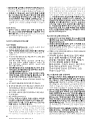
6. Before use
It is essential that the safety precautions printed in these
operating instructions are read and observed.
-CAUTION-
Disconnect the tool from the mains supply.
If extension cables are used: Only extension cables of a
type approved for the intended use and of adequate cross
section may be used. Failure to observe this point may
result in reduced performance and could cause the cable
to overheat. Damaged extension cables must be replaced.
The recommended cable cross-sections and maximum
lengths are:
Conductor cross-section
Mains voltage 1.5 mm
2
2.0 mm
2
2.5 mm
2
3.5 mm
2
100 V 20 m 40 m
110–120 V 20 m 40 m
220–230 V 50 m 80 m
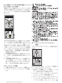
6.1 Side handle
6.1.1 Fitting the side handle
1. Screw the side handle onto the tool and tighten it
securely.
6.1.2 Fitting the side handle in a different position
1. Remove the screw plug at the position where the side
handle is to be fitted (e.g. for left-handed use). The
grip at the end of the side handle can be unscrewed
and used as a screwdriver.
2. Screw the side handle onto the tool at the desired
position and tighten it securely.
3. Insert the screw plug in the exposed threaded hole.
6.1.3 Adjusting the extraction head / water swivel (and
side handle)
1. Press the water swivel lock out of the gap between
the locking ring and the water swivel/extraction head.
2. Release the locking ring between the chuck and side
handle.
5.2.6 Protective equipment
Never use the tool without the applicable protective
equipment:
● Never operate the tool without the water swivel /
extraction head.
● An additional means of securing the drill stand must
be employed when used for horizontal drilling with vac-
uum attachment.
● The drill stand must be fastened by means of an
anchor or quick-release brace when used for overhead
drilling.
● Use of the water collector system in conjunction
with a wet-type vacuum cleaner is mandatory when
carrying out wet overhead drilling.
Printed: 08.07.2013 | Doc-Nr: PUB / 5069522 / 000 / 01

8
1. Open the chuck by turning it counter-clockwise (as
seen from the front end of the chuck).
2. Insert the diamond core bit in the chuck.
3. Push the diamond core bit into the chuck and rotate
the core bit until it engages.
4. Close the chuck by turning it clockwise (as seen from
the front end of the chuck).
5. Check that the core bit it is securely seated by grip-
ping it and attempting to pull it away from the chuck.
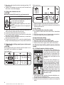
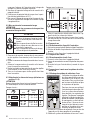
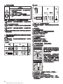
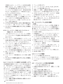
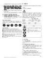
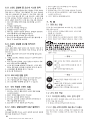
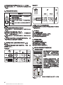
6.3 Selecting the drilling speed (gear selector posi-
tions 1-2-3)
-CAUTION-
Do not operate the gear selector while the tool is run-
ning. Wait until rotation has stopped.
Hand-held use
278663
4
3
/4" - 6
1
/2"
2
5
/8" - 4
1
/4"
1
/2" - 2
1
/2"
I
II
III
1
5
/8" - 2
1
/2"
1
/2" - 1
1
/2"
II
III
122 - 162
67 - 112
12 - 62
40 - 62
12 - 37
mm
Inch
Drill-stand use
1. Select the gear according to the table on the tool.
2. Move the gear selector to the desired setting while
rotating the core bit.
6.4 Dry drilling
6.4.1 Connecting the extraction system
1. Unscrew the cover from the water swivel / extraction
head.
2. Insert the extraction hose in the extraction connection.
3. Close the water valve in the side handle.
6.5 Hand-held wet drilling
6.5.1 Connecting the water supply
1. Close the water valve in the side handle.
2. Close the cover on the dust extraction connection.
3. Connect the water supply hose (hose connector).
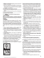
6.6 Hand-held wet drilling with the water collection
system
6.6.1 Fitting the water collection system
Use of the water collection sys-
tem permits water to be drained
away from the core bit thus avoid-
ing soiling the surrounding area.
Best results are achieved in con-
junction with a wet-type vacuum
cleaner.
Use of the water collection sys-
tem in conjunction with a wet-
type vacuum cleaner is manda-
tory for overhead drilling. Posi-
tion the side handle and water
swivel / extraction head so that
the water collection system can
be fitted without obstruction. The
centering ring and seal must be
of a size suitable for the core bit
diameter used.
1. From below the tool, position the water collection sys-
tem on the two mounting pins.
2. Swing the water collection system towards the front.
3. Secure the water collection system by turning the
knob.
-CAUTION-
■ The core bit may become hot during
use or during sharpening.
■ It may burn your hands.
■ The cutting edges (segments) may cause
injury.
■ Wear safety gloves when changing the
core bit.
3. Move the side handle into the desired position (15°
increments).
4. Tighten the locking ring securely until the teeth and
the water swivel lock engage.
6.2 Fitting the diamond core bit
-CAUTION-
Use only original Hilti core bits and accessories!
Printed: 08.07.2013 | Doc-Nr: PUB / 5069522 / 000 / 01

9
4. Connect a wet-type vacuum cleaner to the front of the
water collection system. Alternatively, the water can
be allowed to flow away through a length of hose
attached to the connector (not permissible for over-
head drilling).
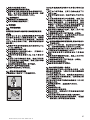
6.6.2 Adjusting the depth gauge
1. Set the depth gauge to the desired depth.
2. Use the clamping screw to secure the depth gauge.
6.7 Using the drill stand
6.7.1 Fastening the drill stand with an anchor
-WARNING-
Use an anchor suitable for the material on which you
are working and observe the anchor manufacturer's
instructions.
-NOTE-
Hilti M12 metal expansion anchors are usually suitable
for fastening diamond core drilling equipment to uncracked
concrete. Under certain conditions it may be necessary
to use an alternative fastening method. Please contact
Hilti Technical Service if you have any questions about
secure fastening.
1. Set the anchor of a type suitable for the material on
which you are working at a distance of 200 mm (ide-
ally) from the center of the point where the hole is to
be drilled.
2. Screw the quick-release spindle into the anchor.
3. Place the drill stand over the quick-release spindle
and position it correctly with the aid of the hole cen-
ter indicator.
4. Screw the nut onto the quick-release spindle but do
not tighten it fully.
5. Use the four leveling screws to level the base plate.
Check that all four leveling screws are in contact with
the surface. The bubble level on the base plate serves
as a leveling aid.
6. Lock the leveling screws by tightening the lock nuts.
7. Use an open-end wrench to tighten the lock nuts.
8. Check to ensure that the drill stand is fastened securely.
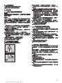
6.7.2 Securing the drill stand with the vacuum pad
A vacuum release valve is incorporated in the baseplate
grip.
VACUUM
VACUUM
Overhead drilling with the drill stand attached only by
vacuum is not permissible.
1. Unscrew the four levelling screws until they project
approx. 5 mm beneath the baseplate.
2. Connect the hose between the vacuum connector on
the baseplate and the vacuum pump.
3. Switch on the vacuum pump and extend the hole
centre indicator. While pressing the vacuum release
valve and observing the hole centre indicator, bring
the baseplate into the desired position. When posi-
tioned correctly, press the baseplate against the work
surface and remove your finger from the vacuum
release valve. Before beginning drilling and during
operation, it must be ensured that the pressure gauge
pointer remains within the green area.
4. The four levelling screws should then be used to lev-
el the baseplate. The spirit level on the baseplate serves
as a levelling aid.
5. Tighten the lock nuts to prevent further movement of
the levelling screws.
6. An additional means of securing the drill stand must
be employed when drilling horizontally (e.g. a chain
attached to an anchor, ...)
7. Check to ensure that the drill stand is fastened secure-
ly.
6.7.3 Securing the drill stand with a quick-release
brace (e.g. between floor and ceiling)
1. Extend the hole centre indicator and then use it as an
aid to bring the drill stand into alignment with the cen-
tre point of the hole to be cored.
2. Position the end of the quick-release brace carefully
in the inner oval of the baseplate (not on the level indi-
cator or pressure gauge).
3. Secure the baseplate by applying slight pressure with
the quick-release brace.
4. The four levelling screws should then be used to lev-
el the baseplate. The spirit level on the baseplate serves
as a levelling aid.
5. Tighten the lock nuts to prevent further movement of
the levelling screws.
6. Tighten the quick-release brace securely.
7. Check to ensure that the drill stand is fastened secure-
ly.
6.8 Water collection system for use with the drill stand
Use of the water collection system permits water to be
drained away from the core bit thus avoiding soiling the
surrounding area. Best results are achieved in conjunc-
tion with a wet-type vacuum cleaner.
Use of the water collection system in conjunction with
a wet-type vacuum cleaner is mandatory for overhead
drilling. The drill stand must be set up at 90° to the work
surface.
The water collector sleeve and seal must be of a size
suitable for the core bit diameter used.
1. Slacken the column adjusting lever until the locating
lugs are disengaged.
2. Tilt the frame.
Printed: 08.07.2013 | Doc-Nr: PUB / 5069522 / 000 / 01

10
3. Fit the water collector holder.
4. Bring the frame back to the vertical position.
5. Close the adjusting levers until the locating lugs are
fully engaged and the frame is again secured.
6. Lift the holder and push the water collector cup under
the retainer as far as it will go.
7. Connect a wet-type vacuum cleaner to the water col-
lector cup or connect a length of hose through which
the water can flow away.
6.9 Mounting the tool on the drill stand
-CAUTION-
The release lever on the drill stand must be in the open
position and the carriage should be at the top of its travel.
The drilling advance mechanism must be locked (chain
arrestor engaged).
1. Fit the tool interface plate onto the two mounting pins
on the drill stand. (6.9.1)
2. Swing the tool briskly toward the drill stand. It should
be heard to engage. (6.9.2)
3. Check the position of the release lever in order to
ensure that the tool is engaged and attached secure-
ly to the drill stand. (6.9.3)
4. Insert the switch lock in the grip opening. The switch
lock is used to hold the switch in the ON position dur-
ing sustained operation.
5. Close the water valve in the side handle.
6. Connect the water supply.
6.10 Fitting the hand wheel
1. Fit the hand wheel onto the axle.
2. Secure the hand wheel by tightening the screw knob.
3. The hand wheel may be fitted on either side of the drill
stand.
6.11 Adjusting the drill stand drilling angle
(In increments of 7.5°; adjustable to max. 45°)
1. Slacken the column adjusting levers until the locat-
ing lugs are disengaged.
2. Bring the columns into the desired position.
3. Engage the locating lugs.
4. Move the adjusting levers until the locating lugs are
fully engaged and the frame is again secured.
5. Press in and pivot the adjusting levers to return them
to the vertical position.
6.12 Removing the tool from the drill stand
-CAUTION-
The tool must be disconnected from the electric mains
supply.
The drilling advance mechanism must be locked (chain
arrestor engaged).
1. Close the water valve in the side handle.
2. Disconnect the water supply.
3. Remove the switch lock from the grip.
4. Hold the tool with one hand on the grip and release
the lever on the drill stand.
5. Pivot the tool away from the drill stand.
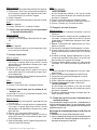
7. Operation
7.1 Connect the tool to the electric mains supply
The voltage given on the rating plate must correspond
to the voltage provided by the mains supply.
1. Check that the tool is switched off or, respectively,
remove the switch lock.
2. Insert the supply cord plug in the mains socket.
3. Press the "ON" button on the PRCD ground fault inter-
rupter (the lamp must light).
4. Press the "TEST" button on the PRCD ground fault
interrupter (the lamp must not
light).
-DANGER-
If the indicator continues to light, further operation of
the machine ist not permissible. Have the machine repair -
ed by a qualified specialist using genuine Hilti spare parts.
5. Press the "ON" button on the PRCD ground fault inter-
rupter (the lamp must light).
-CAUTION-
■ The tool and the coring operation cre-
ate noise.
■ Excessive noise may damage the hear-
ing.
■ Wear ear protection.
-CAUTION-
■ The coring operation may cause haz-
ardous fragments to fly off.
■ Flying fragments may cause injury to
the eyes or other parts of the body.
■ Wear eye protection and a safety hel-
met.
7.2 Dry drilling
7.2.1 Fitting the hole-starting aid
A different hole-starting aid is required for each diamond
core bit diameter.
1. Fit the hole-starting aid into the front end of the dia-
mond core bit.
7.2.2 Vacuum cleaner with power socket for electric
tools
The vacuum cleaner starts automatically after switch-
ing on the electric tool. Switching off the electric tool
also causes the vacuum cleaner to be switched off after
a short delay.
Switching on
1. Press the on / off switch on the tool.
2. With the hole-starting aid fitted, begin drilling and
continue until the projecting segments have estab-
lished a kerf in the base material.
3. Switch the tool off.
Printed: 08.07.2013 | Doc-Nr: PUB / 5069522 / 000 / 01

11
4. Remove the hole-starting aid and continue drilling.
Switching off
1. Switch the tool off.
2. Remove the core if necessary.
7.2.3 Vacuum cleaner without power socket for elec-
tric tools
Switching on
1. Switch the vacuum cleaner on.
2. Press the on / off switch on the tool.
Switching off
1. Switch the tool off.
2. Allow the vacuum cleaner to run for a short time in
order to remove remaining dust before switching off.
7.3 Hand-held wet drilling
Switching on
1. Open the water valve in the side handle until the desired
water volume flows. The water flow volume can be
observed at the indicator on the hand grip.
2. Press the on / off switch
3. When starting a hole, hold the tool at a slight angle
to the work surface. This makes hole-starting easier.
4. Once the hole has been started, bring the tool into the
90° position and continue drilling.
Switching off
1. Switch the tool off.
2. Close the water valve on the side handle.
7.4 Hand-held wet drilling using the water collection
system
The crosshair marks at the front end of the water col-
lection system serve as an accurate positioning aid.
Switching on
1. Switch on the water extraction system (if used).
2. Open the water valve on the side handle slowly until
the desired water volume flows. Use the indicator on
the side handle to check the water flow rate.
3. Press the on / off switch.
4. Hold the tool at a slight angle to the work surface
when starting a hole. This makes hole-starting easier.
5. After starting the hole, bring the tool into the 90° posi-
tion and continue drilling.
Switching off
1. Switch the tool off.
-WARNING-
When drilling overhead, any water remaining in the
core bit must not be allowed to run down over the
tool.
2. Close the water valve on the side handle.
3. Switch off the vacuum cleaner (if used).
4. Remove the core if necessary.
7.5 Wet drilling using the drill stand
Switching on
1. Switch on the (wet) vacuum cleaner (if used).
2. Open the water valve at the side handle slowly until
the desired volume of water flows. The indicator at
the side handle can be used to check the water flow
rate.
3. Use the switch actuator to run the tool in sustained
operation mode.
4. Release the chain arrestor.
5. Bring the core bit into contact with the work surface
by turning the hand wheel.
6. Apply only slight pressure to the core bit when begin-
ning drilling and then increase pressure once the core
bit has become centred.
7. Keep an eye on the overload indicator while drilling.
Pressure on the core bit must be reduced if the over-
load indicator lights.
Switching off
1. Close the water regulation valve at the side handle.
2. Pull the core bit out of the hole.
3. Engage the chain arrestor.
4. Switch the tool off.
5. Switch off the vacuum cleaner (if used).
6. Remove the core if necessary.
7. Switch the tool off.
-WARNING-
When drilling overhead, any water remaining in the
core bit must not be allowed to run down over the
tool.
8. Ensure stability of the drill stand by lowering the tool
and core bit to the baseplate.
7.6 Procedure in the event of the core bit sticking
The slip clutch will be activated if the core bit sticks. The
power tool must then be switched off by the operator.
To release the core bit, proceed as follows:
Using an open-end wrench to release the core bit
1. Disconnect the supply cord plug from the power out-
let.
2. Grip the core bit close to the connection end with a
suitable open-end wrench and rotate the core bit to
release it.
3. Plug the supply cord back into the power outlet.
4. Continue the drilling operation.
Using the spider wheel to release the core bit (for use
with the drill stand)
1. Disconnect the supply cord plug from the power out-
let.
2. Release the core bit by rotating it with the spider wheel.
3. Plug the supply cord back into the power outlet.
4. Continue the drilling operation.
7.7 Transport and storage
-NOTE-
– Store and transport the power tool in is toolbox when
possible.
– Open the water flow regulator before storing the pow-
er tool. Especially at temperatures below freezing, take
care to ensure that no water remains in the power tool.
Printed: 08.07.2013 | Doc-Nr: PUB / 5069522 / 000 / 01

12
8. Care and maintenance
Disconnect the supply cord plug from the socket.
8.1 Care of core bits
Remove any dirt adhering to the core bits and protect
their surfaces from corrosion by rubbing them with an
oily cloth from time to time. Always keep the connec-
tion end clean and slightly greased.
8.2 Care of the tool
Check that the supply cord plug is disconnected.
-CAUTION-
Keep the power tool, especially its grip surfaces, clean
and free from oil and grease. Do not use cleaning agents
which contain silicone.
The outer casing of the tool is made from impactresis-
tant plastic. Sections of the grip are made from a syn-
thetic rubber material. Never operate the tool when the
ventilation slots are blocked. Clean the ventilation slots
carefully using a dry brush. Do not permit foreign objects
to enter the interior of the tool. Clean the outside of the
tool at regular intervals with a slightly damp cloth. Do not
use a spray, steam pressure cleaning equipment or run-
ning water for cleaning. This may negatively affect the
electrical safety of the tool.
Clean the chuck and the clamping segments with a cloth
at regular intervals and lubricate these parts with Hilti
lubricant spray. Remove any dirt and fragments from
the chuck.
Remove the filter in the water intake at the side handle
from time to time and rinse the filter sieve under run-
ning water in the direction opposite to the normal water
flow.
If the water flow indicator has become dirty, remove and
clean the parts. Do not use abrasive agents or sharp
objects to clean the sight glass. This may negatively
affect functionality of the water flow indicator.
8.3 Maintenance of the tool
Check all external parts of the tool for damage at regu-
lar intervals and check that all operating controls func-
tion faultlessly. Do not operate the tool when parts are
damaged or when operating controls do not function
faultlessly. The tool should be repaired at a Hilti service
centre.
Repairs to the electrical section of the tool may be car-
ried out by trained electrical specialists only.
8.4 Care of the drill stand
8.4.1 Care of the chain
Check the chain guides to ensure they remain clean and
free from drilling slurry. The chain must always be pro-
tected by a film of grease.
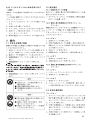
8.5 Maintenance of the drill stand
8.5.1 Adjusting the movement
Movement should be easy but without play.
The movement can be adjusted by way of screws (2 at
the top and 2 at the bottom).
8.5.1.1 Stiffer movement
1. Release the lower screw.
2. Tighten the upper screw as far as necessary.
3. Tighten the lower screw as far as it will go.
8.5.1.2 Easier movement
1. Release the upper screw.
2. Tighten the lower screw as far as it will go.
8.5.2 Adjusting the chain tension
When the carriage is in the end position, the chain should
sag only slightly when running horizontally. Chain ten-
sion can be adjusted by way of two screws (chain sym-
bol on the cover).
● Turning in a clockwise direction increases chain ten-
sion.
● Turning in a counter-clockwise direction decreases
chain tension.
Both chains must be tensioned equally.
Printed: 08.07.2013 | Doc-Nr: PUB / 5069522 / 000 / 01

13
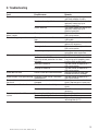
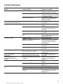
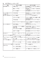
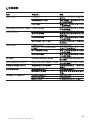
9. Troubleshooting
Fault Possible cause Remedy
The tool doesn't start. Fault in mains supply Plug in another electric appliance
and check whether it works.
Supply cord or plug defective The cord should be checked and
replaced if necessary by an
electrical specialist.
Switch defective The switch should be checked and
replaced if necessary by an
electrical specialist.
Motor runs but the core bit Gearing defective The tool should be repaired at a
doesn't rotate. Hilti service centre.
Rate of drilling progress decreases. Water pressure / water flow rate too Regulate the water flow rate at the
high side handle.
Core bit defective Check the core bit for damage and
replace it if necessary.
Gearing defective The tool should be repaired at a
Hilti service centre.
Core bit segments polished Resharpen the core bit on a sharp-
ening plate under water flow.
Motor cuts out. Tool stops running. Guide the tool straight.
Tool has overheated. The motor's Ease the load on the tool and allow
thermal overload protection has been it to run up to full speed by press-
activated. ing the switch several times.
Electronics defective The tool should be repaired at a
Hilti service centre.
Cooling fan defective The tool should be repaired at a
Hilti service centre.
Water does not flow. Filter or water flow indicator blocked Remove the filter or water flow
indicator and flush it through.
Water escapes at the gear housing. Shaft seal / water swivel / extraction The tool should be repaired at a
head defective Hilti service centre.
The core bit cannot be inserted in Connection end or chuck dirty or Clean the connection end and
the chuck. damaged chuck. Replace parts if necessary.
Water escapes at the chuck. Connection end or chuck dirty Clean the connection end and
chuck.
Chuck seal defective Check the seal and replace it if
necessary.
Excessive play in the drilling Excessive play at the guides Readjust the guides.
system. Chain inadequately tensioned Tension the chain.
Pivot mechanism loose Tighten the pivot mechanism
adjusting lever (6.11).
Printed: 08.07.2013 | Doc-Nr: PUB / 5069522 / 000 / 01

14
10. Disposal
Most of the materials from which Hilti pow-
er tools are manufactured can be recycled.
The materials must be correctly separated
before they can be recycled. In many coun-
tries, Hilti has already made arrangements for taking
back your old electric tools for recycling. Please ask
your Hilti customer service department or Hilti sales
representative for further information.
Disposal of drilling slurry
With regard to environmental aspects, allowing drilling
slurry to flow directly into rivers, lakes or the sewer-
age system without suitable pre-treatment is prob-
lematical. Ask the local authorities for information about
applicable regulations.
We recommend the following pre-treatment:
Collect the drilling slurry (e.g. use a wet-type indus-
trial vacuum cleaner).
Allow the slurry to settle and dispose of the solid mate-
rial at a construction waste disposal site (the addition
of a flocculent may accelerate the settling process).
Water from the drilling slurry (alkaline, ph value > 7)
should be neutralized by adding an acidic neutralizing
agent or large quantity of water before it is allowed to
flow into the sewerage system.
Only for EU countries
Disposal of electric tools together with household waste
is not permissible!
In observance of European Directive on waste electrical
and electronic equipment and its implementation in
accordance with national law, electric tools that have
reached the end of their life must be collected separately
and returned to an environmentally compatible recycling
facility.
11. Manufacturer's warranty – tools
Hilti warrants that the tool supplied is free of defects
in material and workmanship. This warranty is valid so
long as the tool is operated and handled correctly,
cleaned and serviced properly and in accordance with
the Hilti Operating Instructions, and the technical sys-
tem is maintained. This means that only original Hilti
consumables, components and spare parts may be
used in the tool.
This warranty provides the free-of-charge repair or
replacement of defective parts only over the entire lifes-
pan of the tool. Parts requiring repair or replacement
as a result of normal wear and tear are not covered by
this warranty.
Additional claims are excluded, unless stringent
national rules prohibit such exclusion. In particular,
Hilti is not obligated for direct, indirect, incidental
or consequential damages, losses or expenses in
connection with, or by reason of, the use of, or inabil-
ity to use the tool for any purpose. Implied warranties
of merchantability or fitness for a particular purpose
are specifically excluded.
For repair or replacement, send tool or related parts
immediately upon discovery of the defect to the address
of the local Hilti marketing organization provided.
This constitutes Hilti's entire obligation with regard to
warranty and supersedes all prior or contemporane-
ous comments and oral or written agreements con-
cerning warranties.
12. EC declaration of conformity
(original)
Designation: Diamond drilling machine
Type: DD130
Year of design: 2001
We declare, on our sole responsibility, that this product
complies with the following directives and standards:
until 2006/42/EC, 2004/108/EC, EN 61029-1, 2011/65/EU,
EN ISO 12100.
Hilti Corporation, Feldkircherstrasse 100,
FL-9494 Schaan
Paolo Luccini Johannes W. Huber
Head of BA Quality & Process Management Senior Vice President
BA Electric Tools & Accessories BU Diamond
11/2009 11/2009
Technical documentation filed at:
Hilti Entwicklungsgesellschaft mbH
Zulassung Elektrowerkzeuge
Hiltistrasse 6
86916 Kaufering
Deutschland
Printed: 08.07.2013 | Doc-Nr: PUB / 5069522 / 000 / 01

15
Avant de mettre en marche cet
appareil, lire absolument son
mode d’emploi et bien respecter
toutes les consignes.
Le présent mode d’emploi doit
toujours accompagner l’appareil.
Ne prêter ou céder cet appareil à
quelqu’un d’autre qu’en lui four-
nissant aussi le mode d’emploi.
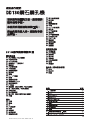
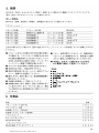
Sommaire Page
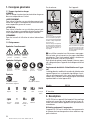
1. Consignes générales 16
2. Description 16
3. Outils et accessoires 17
4. Caractéristiques techniques 17
5. Consignes de sécurité 19
6. Mise en marche 21
7. Utilisation 24
8. Nettoyage et entretien 26
9. Guide de dépannage 27
10. Recyclage 28
11. Garantie constructeur des appareils 28
12. Déclaration de conformité (original) 28
NOTICE ORIGINALE
Appareil de carottage au diamant DD130
Principaux éléments du DD 130
Appareil
Tête de rinçage/d’aspiration
Débitmètre indicateur de l’écoulement d’eau
Indicateur de niveau
Tournevis (poignée latérale)
Poignée latérale
Réglage du débit d’eau
Raccord du tuyau d’eau
Sélecteur de vitesse
Engrenage
Moteur
Interrupteur Marche/Arrêt
Poignée principale
Indicateur de surcharge
Cordon avec PRCD
Plaquette signalétique
Plaque interface
Vis de fermeture (tête de rinçage/d’aspiration)
Couvercle (tête de rinçage/d’aspiration)
Raccord d’aspiration
Serrage de la tête de rinçage
Bague de serrage (tête de rinçage/d’aspiration)
Mandrin
Colonne
Poignée
Chaîne
Colonnes
Clé pour vis à tête 6 pans creux
Chariot
Levier de déverrouillage
Plaquette signalétique
Soupape de dépression
Raccord du flexible de la pompe à vide
Joint de la semelle fixée par dépression
Semelle
Blocage de la chaîne
Volant
Blocage de l’interrupteur Marche/Arrêt
Manomètre
Indicateur de niveau
Levier de réglage
Vis de mise à niveau
Indicateur du centre du trou
Eléments de positionnement
Jauge de profondeur
Mécanisme de verrouillage
Goupilles d’assemblage
Tensionneur de la chaîne
Collecteur d’eau pour forages à main
Bouton de blocage (excentrique)
Vis de serrage
Jauge de profondeur
Corps du collecteur d’eau
Anneau de centrage
Adaptateur de l’anneau de centrage
Joint
Plaque d’assemblage
Collecteur d’eau pour forages avec la colonne
Support
Corps du collecteur d’eau
Joint
햲
햳
햴
햵
햶
햷
햸
햹
햺
햻
햽
햾
햿
헀
헁
헂
헃
헄
헅
헆
쎻
21
쎻
22
쎻
23
쎻
24
쎻
25
쎻
26
쎻
27
쎻
28
쎻
29
쎻
3
0
쎻
31
쎻
32
쎻
3
3
쎻
34
쎻
35
쎻
3
6
쎻
37
쎻
38
쎻
3
9
쎻
40
쎻
41
쎻
42
쎻
43
쎻
44
쎻
45
쎻
46
쎻
47
쎻
48
쎻
49
쎻
50
쎻
51
쎻
52
쎻
53
쎻
54
쎻
55
쎻
56
쎻
57
Printed: 08.07.2013 | Doc-Nr: PUB / 5069522 / 000 / 01
La page est en cours de chargement...
La page est en cours de chargement...
La page est en cours de chargement...
La page est en cours de chargement...
La page est en cours de chargement...
La page est en cours de chargement...
La page est en cours de chargement...
La page est en cours de chargement...
La page est en cours de chargement...
La page est en cours de chargement...
La page est en cours de chargement...
La page est en cours de chargement...
La page est en cours de chargement...
La page est en cours de chargement...
La page est en cours de chargement...
La page est en cours de chargement...
La page est en cours de chargement...
La page est en cours de chargement...
La page est en cours de chargement...
La page est en cours de chargement...
La page est en cours de chargement...
La page est en cours de chargement...
La page est en cours de chargement...
La page est en cours de chargement...
La page est en cours de chargement...
La page est en cours de chargement...
La page est en cours de chargement...
La page est en cours de chargement...
La page est en cours de chargement...
La page est en cours de chargement...
La page est en cours de chargement...
La page est en cours de chargement...
La page est en cours de chargement...
La page est en cours de chargement...
La page est en cours de chargement...
La page est en cours de chargement...
La page est en cours de chargement...
La page est en cours de chargement...
La page est en cours de chargement...
La page est en cours de chargement...
La page est en cours de chargement...
La page est en cours de chargement...
La page est en cours de chargement...
La page est en cours de chargement...
La page est en cours de chargement...
La page est en cours de chargement...
La page est en cours de chargement...
La page est en cours de chargement...
La page est en cours de chargement...
La page est en cours de chargement...
La page est en cours de chargement...
La page est en cours de chargement...
La page est en cours de chargement...
La page est en cours de chargement...
La page est en cours de chargement...
La page est en cours de chargement...
La page est en cours de chargement...
La page est en cours de chargement...
La page est en cours de chargement...
La page est en cours de chargement...
La page est en cours de chargement...
La page est en cours de chargement...
La page est en cours de chargement...
La page est en cours de chargement...
La page est en cours de chargement...
La page est en cours de chargement...
La page est en cours de chargement...
La page est en cours de chargement...
La page est en cours de chargement...
La page est en cours de chargement...
La page est en cours de chargement...
La page est en cours de chargement...
La page est en cours de chargement...
La page est en cours de chargement...
La page est en cours de chargement...
La page est en cours de chargement...
La page est en cours de chargement...
La page est en cours de chargement...
La page est en cours de chargement...
La page est en cours de chargement...
La page est en cours de chargement...
La page est en cours de chargement...
La page est en cours de chargement...
La page est en cours de chargement...
La page est en cours de chargement...
-
 1
1
-
 2
2
-
 3
3
-
 4
4
-
 5
5
-
 6
6
-
 7
7
-
 8
8
-
 9
9
-
 10
10
-
 11
11
-
 12
12
-
 13
13
-
 14
14
-
 15
15
-
 16
16
-
 17
17
-
 18
18
-
 19
19
-
 20
20
-
 21
21
-
 22
22
-
 23
23
-
 24
24
-
 25
25
-
 26
26
-
 27
27
-
 28
28
-
 29
29
-
 30
30
-
 31
31
-
 32
32
-
 33
33
-
 34
34
-
 35
35
-
 36
36
-
 37
37
-
 38
38
-
 39
39
-
 40
40
-
 41
41
-
 42
42
-
 43
43
-
 44
44
-
 45
45
-
 46
46
-
 47
47
-
 48
48
-
 49
49
-
 50
50
-
 51
51
-
 52
52
-
 53
53
-
 54
54
-
 55
55
-
 56
56
-
 57
57
-
 58
58
-
 59
59
-
 60
60
-
 61
61
-
 62
62
-
 63
63
-
 64
64
-
 65
65
-
 66
66
-
 67
67
-
 68
68
-
 69
69
-
 70
70
-
 71
71
-
 72
72
-
 73
73
-
 74
74
-
 75
75
-
 76
76
-
 77
77
-
 78
78
-
 79
79
-
 80
80
-
 81
81
-
 82
82
-
 83
83
-
 84
84
-
 85
85
-
 86
86
-
 87
87
-
 88
88
-
 89
89
-
 90
90
-
 91
91
-
 92
92
-
 93
93
-
 94
94
-
 95
95
-
 96
96
-
 97
97
-
 98
98
-
 99
99
-
 100
100
-
 101
101
-
 102
102
-
 103
103
-
 104
104
-
 105
105


Hilti DD 130 Mode d'emploi
- Catégorie
- Fournitures pour aspirateur
- Taper
- Mode d'emploi
dans d''autres langues
- English: Hilti DD 130 Operating instructions
