Miller JA458805 Le manuel du propriétaire
- Catégorie
- Système de soudage
- Taper
- Le manuel du propriétaire
Ce manuel convient également à

February
1981
FORM:
OM-1522B
Effective
With
Serial
No.
JA458805
MODEL
SWINGARC
DIGITAL
-
1
12
SWINGARC
DIGITAL
-
1
16
OWN
ERS
MANUAL
fullER
MILLER
ELECTRIC
MFG.
Co.
718
S.
BOUNDS
ST.
P.O.
Box
1079
APPLETON,
WI
54912
USA
ADDITIONAL
COPY
PRICE
85
CENTS
NWSA
CODE
NO.
4579
PRINTED
IN
U.S.A.

L~
~
L~
~
~
~C~
LIMITED
WARRANTY
EFFECTIVE:
JUNE
1,
1979
This
warranty
supersedes
all
previous
MILLER
warranties
and
is
ex
clusive
with
no
other
guarantees
or
warranties
expressed
or
implied.
LIMITED
WARRANTY-Subject
to
the
terms
and
conditions
As
a
matter
of
general
policy
only,
Miller
may
honor
claims
hereof,
Miller
Electric
Mfg.
Co.,
Appleton,
Wisconsin
warrants
submitted
by
the
original
user
within
the
foregoing
periods.
to
its
Distributor/Dealer
that
all
new
and
unused
Equipment
(
furnished
by
Miller
is
free
from
defect
in
workmanship
and
In
the
case
of
Millers
breach
of
warranty
or
any
other
duty
material
as
of
the
time
and
place
of
delivery
by
Miller.
No
war-
with
respect
to
the
quality
of
any
goods,
the
exclusive
remedies
ranty
is
made
by
Miller
with
respect
to
engines,
trade
ac-
therefore
shall
be,
at
Millers
option
(11
repair
or
(2)
replacement
cessories
or
other
items
manufactured
by
others.
Such
or,
where
authorized
in
writing
by
Miller
in
appropriate
cases,
(3)
engines,
trade
accessories
and
other
items
are
sold
subject
to
the
reasonable
cost
of
repair
or
replacement
at
an
authorized
the
warranties
of
their
respective
manufacturers,
if
any
.
All
Miller
service
station
or
(4)
payment
of
or
credit
for
the
purchase
engines
are
warranted
by
their
manufacturer
for
one
year
from
price
(less
reasonable
depreciation
based
upon
actual
use)
upon
date
of
original
purchase,
return
of
the
goods
at
Customers
risk
and
expense.
Upon
receipt
of
notice
of
apparent
defect
or
failure,
Miller
shall
instruct
the
clai-
I~
Except
as
specified
below,
Millers
warranty
does
not
apply
mant
on
the
warranty
claim
procedures
to
be
followed.
to
components
having
normal
useful
life
of
less
than
one
(1)
year,
such
as
spot
welder
tips,
relay
and
contactor
points,
ANY
EXPRESS
WARRANTY
NOT
PROVIDED
HEREIN
AND
MILLERMATIC
parts
that
come
in
contact
with
the
welding
ANY
IMPLIED
WARRANTY,
GUARANTY
OR
REPRESENTA
wire
including
nozzles
and
nozzle
insulators
where
failure
does
TION
AS
TO
PERFORMANCE,
AND
ANY
REMEDY
FOR
riot
result
from
defect
in
workmanship
or
material.
BREACH
OF
CONTRACT
WHICH,
BUT
FOR
THIS
PROVISION,
MIGHT
ARISE
BY
IMPLICATION,
OPERATION
OF
LAW,
Miller
shall
be
required
to
honor
warranty
claims
on
war-
CUSTOM
OF
TRADE
OR
COURSE
OF
DEALING,
INCLUDING
ranted
Equipment
in
the
event
of
failure
resulting
from
a
defect
ANY
IMPLIED
WARRANTY
OF
MERCHANTABILITY
OR
OF
within
the
following
periods
from
the
date
of
delivery
of
Equip-
FITNESS
FOR
PARTICULAR
PURPOSE,
WITH
RESPECT
TO
ment
to
the
original
user:
ANY
AND
ALL
EQUIPMENT
FURNISHED
BY
MILLER
IS
EX
CLUDED
AND
DISCLAIMED
BY
MILLER.
1.
Arc
welders,
power
sources
and
components
. .
1
year
2.
Original
main
power
rectifiers
3
years
EXCEPT
AS
EXPRESSLY
PROVIDED
BY
MILLER
IN
(labor
-
1
year
only)
WRITING,
MILLER
PRODUCTS
ARE
INTENDED
FOR
3.
All
welding
guns
and
feeder/guns
90
days
ULTIMATE
PURCHASE
BY
COMMERCIAL/INDUSTRIAL
r
4.
All
other
Millermatic
Feeders
1
year
USERS
AND
FOR
OPERATION
BY
PERSONS
TRAINED
AND
5.
Replacement
or
repair
parts,
exclusive
oflabor
.
60
days
EXPERIENCED
IN
THE
USE
AND
MAINTENANCE
OF
d
6.
Batteries
6
months
WELDING
EQUIPMENT
AND
NOT
FOR
CONSUMERS
OR
CONSUMER
USE.
MILLER
WARRANTIES
DO
NOT
EXTEND
provided
that
Miller
is
notified
in
writing
within
thirty
(30)
days
TO,
AND
NO
RESELLER
IS
AUTHORIZED
TO
EXTEND
of
the
date
of
such
failure
MILLERS
WARRANTIES
TO,
ANY
CONSUMER.
~t,
J_
..~
J~
t,
J_
~__t,
J? j?

ERRATA
SHEET
After
this
manual
was
printed,
refinements
in
equipment
design
occurred.
This
sheet
lists
exceptions
to
data
appearing
later
in
this
manual.
FRE
C(PY
AMENDMENT
TO
SECTION
3
INSTALLATION
Add
Section
3-20.
PULLEY
ADJUSTMENT
RETU~
~U
r~JL~R
The
pulley
on
the
boom
over
which
the
welding
wire
runs
can
be
adjusted.
Adjustment
is
necessary
when
changing
from
a
fine
diameter
wire
(0.030-1/16
in.)
to
a
larger
diameter
wire
(3/32-1/8
in.)
to
prevent
a
sharp
bend
in
the
wire
while
feeding.
To
adjust
the
pulley
proceed
as
follows:
~Il~I~
ELECTRIC
SHOCK
can
kill.
0
Shut
down
the
we/ding
power
source
and
wire
feeder
and
ensure
that
they
cannot
be
accidentally
energized
before
proceeding.
1.
Retract
wire
and
change
to
new
wire
size.
2.
Loosen
nuts
securing
pulley
shaft
to
boom.
3.
Move
shaft
to
desired
hole:
Upper
hole
for
fine
diameter
wires,
lower
hole
for
large
diameter
wires.
4.
Tighten
nuts
to
secure
pulley
shaft.
5.
Thread
welding
wire.
AMENDMENT
TO
SECTION
7
-
TROUBLESHOOTING
BE
SURE
TO
PROVIDE
MODEL
AND
SERIAL
NUMBERS
WHEN
ORDERING
REPLACEMENT
PARTS.
OM-l522BPageA
9/28/81
Item
Dia.
Part
Replaced
QuantiW
Model
116
No.
Mkgs.
No.
With
Description
12
28
047311
083687
CORD,motorl5ft(EffW/JB558743)
1
28
047
312
083
693
CORD,
motorl9ft(EFfW/JB558743)
1
33
PLG8
048
380
079 534
071
892
079
535
RECEPTACLE
W/SOCKETS
(Eff
W/JB558743)
(consisting
of)
..
.
TERMINAL,
male
1
14
1
14
42
049
912
047
553
MOTOR
ASSEMBLY
(Elf
W/JB558742)
1 1
43
PLG9
048
306
047
636
HOUSING
PLUG
&
PINS
(Elf
W/JB558743)
(consisting
of)
1
1
60
079
535
079
619
079
535
Deleted
.
TERMINAL,
male
(qty
chg)
14
14
61
VR1
058
112
072010
082722
BUSHING,O.316IDx7/16x13/16x3/16
VARISTOR,0.6Wl75volts(EffW/JB510792)
4
1
4
1
130
023
562
020
265
CABLETIE,0
-
1-3/4
1
1
152
079644
082966
BOOM(EftW/JB512075)
1
152
080818
082967
BOOM(EffW/JB512075)
1
153
601
872
601
872
NUT(qtychg)
4
4
154
602213
602213
082970
WASHER(qtychg)
SHAFT,pulley(EfIW/JB512075)
4
1
4
1

Z6LOLS8~
N/S
4~!M
GAR3Ofl~
s~opO~p.j
JOd
WDJ6~!Q
~!~J!3
L-L
oJn8!,J
cc
2cc,
cc
000
c~
~
.cc
,
<
<
~
<
c,O~0O
~
~
>;
~
ti
SZO
£80-3
N
W8J6C!G
~
1PLi
G
LJLJ
~)
PF1~
.p.Oc
01
1)105)0
0110
-
cc,flc.
Cc
lat).
I.
sScOa
cor.no,
01
.~dS10
AI0~
aJunSvlnSnvncOA
1V
0N£~?,t1a
0010cc
AOl
000
10
5000.
3000
10,
tT
-4W>
7
~
~.
.
~
10)
E
Co
~0)
CO
a
4-.
0
I
0
I
N
a,
0)
U
C
a,
E
Ic
A
SO
0d~d
~\
It

TABLE
OF
CONTENTS
Section
No.
Page
No.
SECTION
1
-
SAFETY
RULES
FOR
OPERATION
OF
ARC
WELDING
POWER
SOURCE
1
-
1.
Introduction
1
1
-
2.
General
Precautions
1
1
-3.
ArcWelding
7
1
-4.
StandardsBookletlndex
10
SECTION
2
-
INTRODUCTION
2-1.
General
12
2
-
2.
Receiving-Handling
12
2
-
3.
Description
12
2-4.
Safety
12
SECTION
3
-
INSTALLATION
3
-
1.
Location
And
Assembly
12
3-2.
DriveMotor
14
3
-
3.
Installation
Of
Wire
Support
14
3
-
4.
Reinstallation
Of
Hub
Assembly
14
3
-
5.
Installation
Of
Wire
Reel
14
3
-6.
DriveRollAndWireGuidelnstallation
15
3
-
7.
Water
Control
Kit
(Optional)
Connections
16
3
-
8.
Shielding
Gas
Connections
16
3
-
9.
Welding
Gun
Connections
16
3-10.
Boom
Adjustments
17
3-11.
Motor
Control
Connection
17
3-12.
GunTriggerConnection
17
3-13.
Weld
Cable
Connection
17
3-14.
115
Volts/Contactor
Connection
17
3-15.
Remote
Control
Connection
18
3-16.
Installation
Of
Spool-Type
Wire
18
3-17.
Installation
Of
Reel-Type
Wire
18
3-18.
Adjustment
Of
Hub
Tension
18
3-19.
WeldingWireThreading
18
SECTION
4
-
FUNCTION
OF
CONTROLS
4
-
1.
Power
Switch
19
4
-
2.
Remote
Control
Receptacle
And
Switch
19
4
-
3.
Purge
Button
19
4
-
4.
Inch
Switch
19
4
-
5.
Wire
Speed
Control
19
4-6.
InchesPerMinuteMeter
19
4-7.
Reset
Circuit
Breaker
19
4
-
8.
Burnback
Control
19
SECTION
5
-
SEQUENCE
OF
OPERATION
5
-
1.
Gas
Metal-Arc
Welding
(GMAW)
19
5
-
2.
Shutting
Down
20
SECTION
6
-
MAINTENANCE
6
-
1.
Inspection
And
Upkeep
20
6
-
2.
Cleaning
Of
Drive
Rolls
20
6-3.
Fuse
20
6
-
4.
Brush
Inspection
&
Replacement
20
SECTION
7
-
TROUBLESHOOTING
PARTS
LIST


SECTION
1
-
SAFETY
RULES
FOR
OPERATION
OF
ARC
WELDING
POWER
SOURCE
SECTION
1
-
REGLES
DE
SECURITE
POUR
LE
FONCTIONNEMENT
DU
POSTE
DE
SOUDAGE
A
LARC
1-1.
INTRODUCTION
-
We
learn
by
experience.
Learning
safety
through
personal
experience,
like
a
child
touching
a
hot
stove
is
harmful,
wasteful,
and
un
wise.
Let
the
experience
of
others
teach
you.
Safe
practices
developed
from
experience
in
the
use
of
~.
welding
and
cutting
are
described
in
this
manual.
Research,
development,
and
field
experience
have
evolved
reliable
equipment
and
safe
installation,
opera-
tion,
and
servicing
practices.
Acidents
occur
when
equipment
is
improperly
used
or
maintained.
The
reason
for
the
safe
practices
may
not
always
be
given.
Some
are
based
on
common
sense,
others
may
require
technical
volumes
to
explain.
It
is
wiser
to
follow
the
rules.
Read
and
understand
these
safe
practices
before
at
tempting
to
install,
operate,
or
service
the
equipment.
Comply
with
these
procedures
as
applicable
to
the
par
ticular
equipment
used
and
their
instruction
manuals,
for
personal
safety
and
for
the
safety
of
others.
Failure
to
observe
these
safe
practices
may
cause
serious
injury
or
death.
When
safety
becomes
a
habit,
the
equipment
can
be
used
with
confidence.
These
safe
practices
are
divided
into
two
Sections:
1
-
General
Precautions,
common
to
arc
welding
and
cutting;
and
2
-
Arc
Welding
(and
Cutting)
(only).
Reference
standards:
Published
Standards
on
safety
are
-
also
available
for
additional
and
more
complete
pro
cedures
than
those
given
in
this
manual.
They
are
listed
in
the
Standards
Index
in
this
manual.
ANSI
Z49.1
is
the
most
complete.
The
National
Electrical
Code,
Occupational
Safety
and
Health
Administration,
local
industrial
codes,
and
local
inspection
requirements
also
provide
a
basis
for
equip
ment
installation,
use,
and
service.
1-2.
GENERAL
PRECAUTIONS
A.
Burn
Prevention
Wear
protective
clothing
-
leather
(or
asbestos)
gauntlet
gloves,
hat,
and
high
safety-toe
shoes.
Button
shirt
collar
and
pocket
flaps,
and
wear
cuffless
trousers
to
avoid
entry
of
sparks
and
slag.
Wear
helmet
with
safety
goggles
or
glasses
with
side
shields
underneath,
appropriate
filter
lenses
or
plates
(protected
by
clear
cover
glass).
This
is
a
MUST
for
welding
or
cutting,
(and
chipping)
to
protect
the
eyes
from
radiant
energy
and
flying
metal.
Replace
cover
glass
when
broken,
pitted,
or
spattered.
See
1-3A.2.
Avoid
oily
or
greasy
clothing.
A
spark
may
ignite
them.
Hot
metal
such
as
electrode
stubs
and
workpieces
should
never
be
handled
without
gloves.
1-1.
INTRODUCTION
-
Contrairement
a
lappren
tissage
de
Ia
vie,
lapprentissage
de
Ia
sØcuritØ
par
ox
pØrience
personnelle,
comme
lenfant
qui
touche
un
poŒle
chaud,
est
dangereux,
imprudent
et
inutile.
lnstruisez-vous
donc
de
lexpØrience
dautrui.
Des
mØthodes
de
sØcuritØ
issues
de
lexperience
du
soudage
et
du
coupage
sont
dØcrites
dans
le
manuel.
La
recherche,
le
progrŁs
et
lexpØrience
dans
ce
domaine
ont
dØveloppØ
un
materiel
fiable
et
des
mØthodes
de
sØcuritØ
pour
linstallation,
le
fonctionnement
et
lentre
tien.
Des
accidents
se
produisent
lorsque
le
materiel
est
inadequatement
utilisØ
ou
entretenu.
La
raison
de
ces
mØthodes
de
sØcuritØ
pout
ne
pas
Œtre
toujours
donnØe.
Certaines
sont
fondØes
sur
le
sons
commun,
dautres
demanderont
a
Œtre
expliquØes
par
dos
livres
techni
ques.
II
est
plus
sage
de
suivre
los
rŁgles.
Lisez
et
comprenez
ces
mØthodes
de
sØcuritØ
avant
dessayer
dinstaller,
de
faire
fonctionner
ou
do
rØparer
lappareil.
Pour
votre
sØcuritØ
personnolle
et
cello
dautrui,
conformez-vous
a
ces
rŁgles
et
aux
manuels
dinstructions.
Manquer
dobserver
ces
mØthodes
do
sØcuritØ
pourrait
entrainer
des
blessures
graves
ou
memo
Ia
mort.
Quand
Ia
sOcuritØ
devient
une
habitude,
le
materiel
pout
alors
Œtre
utilisØ
en
touto
confiance.
Ces
mØthodes
do
sØcuritØ
sont
divisØes
en
deux
sec
tions:
1
-
Precautions
generales,
communes
au
soudage
et
au
coupage
a
Iarc,
et
2
-
Soudage
a
larc
(et
coupage)
(uniquement).
Normos
de
rØfØrence:
Des
publications
des
normes
amØricainos
de
sØcuritØ
sont
aussi
a
votre
disposition
pour
dautres
modes
opØratoires
plus
complots
quo
ceux
du
present
manuel.
Elles
sont
donnØes
dans
lln
dex
des
Normes
de
ces
regles
do
sØcuritØ.
ANSI
Z49-1
est
Ia
plus
complete.
Les
codes
de
IACNOR,
les
codes
provinciaux
ot
municipaux
donnent
aussi
les
exigences
pour
une
in
stallation,
une
utitisation
et
un
entretien
sOrs.
1-2.
PRECAUTIONS
GENERALES
A.
Prevention
des
brUlures
Portez
des
vOtements
do
protection,
des
gants
a
crispin
en
cuir
(ou
amianto),
un
casque
et
des
chaussures
do
sØcuritO.
Boutonnez
to
cot
do
votre
chemise
et
los
pattes
do
vos
poches,
et
portez
des
pantalons
sans
revers
pour
Øviter
quo
des
Øtincelles
et
du
laitier
no
sy
introduisent.
Portez
un
masque
avec
lunettes
do
sØcuritØ
ou
avec
Øcrans
latØ-raux
do
protection,
des
lunettes
filtrantes
ou
des
couvre-lentilles
(protØgØs
par
un
verre
clair).
Pour
le
soudage
ou
le
coupage
(et
le
burinage),
il
est
OBLIGATOIRE
do
proteger
SOS
yeux
contre
lØnergie
de
rayonnement
et
les
Øclats
do
metal.
Remplacez
le
verre
protecteur
Iorsquil
est
brisØ,
piquØ
ou
quil
a
recu
des
projections.
Voir
1
.3A.2.
Evitez
do
porter
des
habits
imprØgnØs
dhuile
ou
de
graisse.
Une
Øtincelle
pourrait
los
onflammer.
Ne
manipulez
jamais
sans
gants
un
metal
chaud
tel
quo
des
chutes
dØlectrode
et
des
piŁces
a
souder.
OM-1522
Page
1

Medical
first
aid
and
eye
treatment.
First
aid
facilities
anda
qualified
first
aid
person
should
be
available
for
each
shift
unless
medical
facilities
are
close
by
for
im
mediate
treatment
of
flash
burns
of
the
eyes
and
skin
burns.
-
Ear
plugs
should
be
worn
when
working
on
overhead
or
in
a
confined
space.
A
hard
hat
should
be
worn
when
others
work
overhead.
Flammable
hair
preparations
should
not
be
used
by
per
sons
intending
to
weld
or
cut.
B.
Toxic
Fume
Prevention
Adequate
ventilation.
Severe
discomfort,
illness
or
death
can
result
from
fumes,
vapors,
heat,
or
oxygen
enrichment
or
depletion
that
welding
(or
cutting)
may
produce.
Prevent
them
with
adequate
ventilation
as
described
in
ANSI
Standard
Z49.1
listed
1
in
Standards
index.
NEVER
ventilate
with
oxygen.
Lead
-,
cadmium
-,
zinc
-,
mercury
-,
and
beryllium
-
bearing
and
similar
materials,
when
welded
(or
cut)
may
produce
harmful
concentrations
of toxic
fumes.
Ade
quate
local
exhaust
ventilation
must
be
used,
or
each
person
in
the
area
as
well
as
the
operator
must
wear
an
air-supplied
respirator.
For
beryllium,
both
must
be
us
ed.
Metals
coated
with
or
containing
materials
that
emit
toxic
fumes
should
not
be
heated
unless
coating
is
removed
from
the
work
surface,
the
area
is
well
ven
tilated,
or
the
operator
wears
an
air-supplied
respirator.
Work
in
a
confined
space
only
while
it
is
being
ven
tilated
and,
if
necessary,
while
wearing
an
air-supplied
respirator.
Gas
leaks
in
a
confined
space
should
be
avoided.
Leaked
gas
in
large
quantities
can
change
oxygen
con
centration
dangerously.
Do
not
bring
gas
cylinders
into
a
confined
space.
Leaving
confined
space,
shut
OFF
gas
supply
at
source
to
prevent
possible
accumulation
of
gases
in
the
space
if
downstream
valves
have
been
accidently
opened
or
left
open.
Check
to
be
sure
that
the
space
is
safe
before
re-entering
it.
Vapors
from
chlorinated
solvents
can
be
decomposed
by
the
heat
of
the
arc
(or
flame)
to
form
PHOSGENE,
a
highly
toxic
gas,
and
other
lung
and
eye
irritating
pro
ducts.
The
ultraviolet
(radiant)
energy
of
the
arc
can
also
decompose
trichloroethylene
and
per
chioroethylene
vapors
to
form
phosgone.
DO
NOT
WELD
or
cut
where
solvent
vapors
can
be
drawn
into
the
welding
or
cutting
atmosphere
or
where
the
radiant
energy
can
penetrate
to
atmospheres
containing
even
minute
amounts
of
trichioroethylene
or
per
chloroethylene.
C.
Fire
and
Explosion
Prevention
Causes
of
fire
and
explosion
are:
combustibles
reached
by
the
arc,
flame,
flying
sparks,
hot
slag
or
heated
Premiers
soins
et
traitement
des
yeux:
Tout
atolier
devrait
avoir
a
sa
disposition
un
posto
de
premiers
soins
ainsi
quune
personne
compØtento,
a
moms
quur,
ser
vice
medical
no
soit
a
proximitØ
pour
soigner
immediate-
mont
ies
brOlures
des
yeux
et
de
Ia
peau.
Portez
des
bouche-oreilles
iorsque
vous
travaillez
au
plafond
ou
dans
un
espace
restreint.
Portoz
un
casque
lorsque
dautres
personnes
travaillent
au
plafond.
Los
personnes
devant
soudor
ou
couper
ne
doivent
pas
employer
des
preparations
inflammables
pour
leurs
cheveux.
B.
Prevention
des
gax
toxlques
Ventilation
adequate:
Los
gaz,
los
vapeurs,
Ia
chaleur,
un
enrichissement
ou
un
manque
doxygŁne
peuvent
entratner
un
malaise,
une
maladie
ou
mOme
Ia
mort.
Remediez-y
par
Ia
ventilation
dØcrite
dans
Ia
Norme
AN
SI
Z49.1
paragraphe
1
de
lindex
des
Normes.
NE
von
tilez
JAMAIS
a
ioxygŁne.
En
soudant
ou
en
coupant,
les
plomb,
cadmium,
zinc,
mercure
et
beryllium
ou
autres
matØriaux
semblables
peuvent
crØer
des
concentrations
nocives
de
gaz
toxi
ques.
On
doit
avoir
recours
a
une
ventilation
aspiranto
adequate
du
local,
ou
alors
touto
personne
sur
los
lieux,
de
memo
quo
Ia
soudeur,
doit
porter
un
masque
a
ad
duction
dair.
On
doit
employer
los
deux
pour
le
beryllium.
Los
metaux
enrobØs
ou
composes
do
matØriaux
Ømet
tant
des
gaz
toxiques
no
doivent
pas
Œtre
chauffes
a
moms
quo
ionrobago
no
soit
ote
do
Ia
surface
a
travailler,
quo
lo
local
no
soit
bien
ventilØ,
ou
quo
ie
soudeur
no
porte
un
masque
a
adduction
dair.
Ne
travaillez
dans
un
espace
restreint
que
siI
ost
bien
vontilØ
et,
si
necessaire,
portoz
un
masque
a
adduction
dair.
On
doit
eviter
los
fuites
do
gaz
dans
un
espace
restreint.
Les
fuites
de
gaz
on
grando
quantitØ
peuvent
transformer
dangerousement
Ia
concentration
dox
ygŁne.
Namonez
pas
do
bouteilles
de
gaz
dans
un
espace
restreint.
En
quittant
un
espace
restroint,
FERMEZ
le
robinet
dalimentation
do
gaz
de
Ia
bout&lIe.
Ainsi
on
pourra
rentror
en
toute
sØcuritØ
dans
Ia
piŁce,
mOme
si
los
robinots
oval
ont
ete
ouverts
par
accident,
OU
Si
Ofl
les
a
laissØs
ouvorts.
Los
vapeurs
do
dissolvants
chlorØs
pouvent
Œtre
dØcom
posees
par
Ia
chaleur
do
larc
(ou
do
Ia
flamme)
et
former
du
PHOSGENE,
gaz
trØs
toxique,
et
dautres
produits
irritant
les
poumons
et
los
yeux.
Lenergie
ultra-violette
de
Iarc
pout
aussi
decomposer
lee
vapeurs
do
trichloroØthylŁne
at
do
perchloroØthylŁne
pour
former
du
phosgene.
NE
SOUDEZ
PAS
ou
no
coupez
pas
dans
des
endroits
oCi
los
vapeurs
do
dissolvants
peu
vent
Œtre
attirŁes
dans
latmosphŁro
do
soudage
ou
do
coupage
ot
oCi
lØnergie
do
rayonnement
pout
pØnØtrer
dans
des
atmospheres
contenant
des
quantitØs
memo
minuscules
do
trichloroethyIene
ou
do
per
chloroØthyIŁne.
C.
Prevention
des
incendies
et
des
explosions
Los
causes
dincendio
ot
dexplosion
sont
les
com
bustibles
anoints
par
Iarc,
Ia
flamme,
los
etincelies,
le
laitior
chaud
ou
les
matØriaux
chauffes,
le
mauvais
Page
2

material;
misuse
of
compressed
gases
and
cylinders;
and
short
circuits.
BE
AWARE
THAT
flying
sparks
or
falling
slag
can
pass
through
cracks,
along
pipes,
through
windows
or
doors,
and
through
wall
or
floor
openings,
out
of
sight
of
the
goggled
operator.
Sparks
and
slag
can
fly
35
feet.
To
prevent
fires
and
explosion:
Keep
equipment
clean
and
operable,
free
of
oil,
grease,
and
(in
electrical
parts)
of
metallic
particles
that
can
cause
short
circuits.
If
combustibles
are
in
area,
do
NOT
weld
or
cut.
Move
the
work
if
practicable,
to
an
area
free
of
combustibles.
Avoid
paint
spray
rooms,
dip
tanks,
storage
areas,
von
tilators.
If
the
work
cannot
be
moved,
move
com
bustibles
at
least
35
feet
away
out
of
reach
of
sparks
and
heat;
or
protect
against
ignition
with
suitable
and
snug-fitting,
fire-resistant
covers
or
shields.
Walls
touching
combustibles
on
opposite
sides
should
not
bewelded
on
(or
cut).
Walls,
ceilings,
and
floor
near
work
should
be
protected
by
heat-resistant
covers
or
shields.
Fire
watcher
must
be
standing
by
with
suitable
fire
ex
tinguishing
equipment
during
and
for
some
time
after
welding
or
cutting
if:
a.
appreciable
combustibles
(including
building
construction)
are
within
35
feet
b.
appreciable
combustibles
are
further
than
35
feet
but
can
be
ignited
by
sparks
c.
openings
(concealed
or
visible)
in
floors
or
walls
within
35
feet
may
expose
com
bustibles
to
sparks
d.
combustibles
adjacent
to
walls,
ceilings,
roofs,
or
metal
partitions
can
be
ignited
by
radiant
or
conducted
heat.
Hot
work
permit
should
be
obtained
before
operation
to
ensure
supervisors
approval
that
adequate
precautions
have
been
taken.
After
work
is
done,
check
that
area
is
free
of
sparks,
glowing
embers,
and
flames.
An
empty
container
that
held
combustibles,
or
that
can
produce
flammable
or
toxic
vapors
when
heated,
must
never
be
welded
on
or
cut,
unless
container
has
first
been
cleaned
as
described
in
AWS
Standard
A6.O,
listed
3
in
Standards
index.
This
includes:
a
thorough
steam
or
caustic
cleaning
(or
a
solvent
or
water
washing,
depending
on
the
com
bustibles
solubility)
followed
by
purging
and
inerting
with
nitrogen
or
carbon
dioxide,
and
using
protective
equipment
as
recommended
in
A6.O.
Waterfilling
just
below
working
level
may
substitute
for
inerting.
A
container
with
unknown
contents
should
be
cleaned
(see
paragraph
above).
Do
NOT
depend
on
sense
of
smell
or
sight
to
determine
if
it
is
safe
to
weld
or
cut.
emploi
des
gaz
comprimØs
et
des
bouteilles
ainsi
que
los
courts-circuits.
Sachez
que
los
Oclats
dØtincelles
ou
Ia
chute
du
laitier
peuvent
sinfiltrer
dans
les
fissures,
le
long
des
tuyautories,
par
los
fenØtros
et
los
portes
et
par
los
couvertures
des
murs
ou
du
sol,
sans
quo
le
soudeur
portant
des
lunettes
no
les
voie.
Les
Øtincelles
et
los
scones
peuvent
voler
jusqu
35
pieds.
Pour
prØvenir
les
incendies
et
los
explosions:
Veillez
a
ce
que
votre
apparoil
soit
propre
et
en
Øtat
do
marche,
dØnuØ
dhuilo
et
de
graisse,
et
do
particules
do
metal
sur
les
piŁces
Ølectriques
qui
pourraient
entralner
des
courts-circuits.
Si
des
combustibles
so
trouvent
a
proximitØ,
no
soudez
pas,
ne
coupez
pas.
Si
possible,
deplacez
votro
travail
loin
des
combustibles.
Evitez
los
ateliers
do
peinture
au
pistolot,
les
cuvos
dimmorsion,
los
entropts,
los
von
tilateurs.
Si
cola
nest
pas
possible,
placez
los
com
bustibles
a
au
moms
35
pieds
dos
Otincellos
ot
de
Ia
chaleur
et
protegez-les
des
Øtincelles
avec
des
couver
tures
ou
des
Øcrans
protecteurs
adequats,
bion
ajustØs
ot
ignifugØs.
On
ne
doit
pas
souder
(ou
coupor)
le
ctO
oppose
dos
murs
touchant
los
combustibles.
Los
murs,
plafonds
et
planchers
proches
du
travail
doivent
Œtre
protØgØs
par
des
couvertures
ou
Øcrans
protectours
ignifugØs.
Un
surveillant
doit
so
tenir
a
proximitØ
avec
un
materiel
do
lutte
contre
lincendie
adØquat,
pendant
et
quelquo
tomps
aprŁs
to
soudago
ou
le
coupage
si:
a.
Des
quantitØs
appreciables
do
combustibles
(y
compris
une
construction
on
chantier)
so
trouvent
a
moms
do
35
pieds.
b.
Des
quantitØs
appreciables
do
combustibles
sont
a
plus
do
35
piods
mais
pouvont
Otre
onflammØes
par
des
Øtincelles.
c.
Des
ouvertures
(cachØos
ou
visibles)
sur
los
planchers
ou
los
murs
a
moms
do
35
pieds
peuvent
exposer
des
combustibles
aux
Øtincelles.
d.
Los
combustibles
adjaconts
aux
murs,
plafonds,
toits
ou
cloisons
mØtalliquos
peu
vent
Otre
onflammØs
par
une
chaleur
rayon
nante
ou
transmise.
Avant
do
commoncor,
avisoz
le
contremaltro
pour
quiI
sassuro
quo
los
precautions
adØquatos
soiont
prisos.
Uno
fois
lo
travail
terminØ,
vØrifioz
quil
ny
ait
pas
dØtincelles,
do
condros
ardentes
ou
do
flammes
dans
lo
local.
On
no
doit
jamais
souder
ni
coupor
sur
un
recipient
ayant
contonu
dos
combustibles,
ou
pouvant
produiro
des
vapeurs
inflammables
ou
toxiques
a
Ia
chauffo,
Ł
moms
quo
lo
recipient
nait
ete
lavØ
au
prealablo,
com
me
dØcrit
dans
Ia
Norme
AWS
A6.O,
figurant
au
paragrapho
3
do
llndex
des
Normos.
Cola
comprend:
un
nottoyago
a
fond
a
Ia
vapour
ou
au
caustique
(ou
un
lavage
avoc
dissolvant
ou
eau
solon
Ia
solubilitØ
du
combustible)
suivi
dune
purge
ot
dune
in
jection
dazote
ou
do
gaz
carbonique,
on
utilisant
un
equipement
do
protection
comme
recommandØ
dans
IA6-O.
LatmosphŁro
inorto
pout
Otre
romplacØo
par
un
niveau
deau
arrivant
au-dossous
du
travail
Ł
offectuer.
Vous
dovoz
layer
un
recipient
dont
Ia
nature
do
contenu
ost
inconnue
(voir
paragraphe
ci-dessus).
NE
vous
fiez
PAS
a
Iodorat
ou
a
Ia
vuo
pour
dire
si
lon
pout
10
souder
ou
le
couper
en
toute
sØcuritØ.
OM-1522
Page
3

Hollow
castings
or
containers
must
be
vented
before
welding
or
cutting.
They
can
explode.
Explosive
atmospheres.
Never
weld
or
cut
where
the
air
may
contain
flammable
dust,
gas,
or
liquid
vapors
(such
as
gasoline).
D.
Compressed
Gas
Equipment
Standard
precautions.
Comply
with
precautions
in
this
manual,
and
those
detailed
in
CGA
Standard
P-i,
PRECAUTIONS
FOR
SAFE
HANDLING
OF
COM
PRESSED
GASES
IN
CYLINDERS,
listed
6
in
Stan
dards
index.
1.
Pressure
Regulators
Regulator
relief
valve
is
designed
to
protect
only
the
regulator
from
overpressure;
it
is
not
intended
to
pro
tect
any
downstream
equipment.
Provide
such
protec
tion
with
one
or
more
relief
devices.
Never
connect
a
regulator
to
a
cylinder
containing
gas
other
than
that
for
which
the
regulator
was
designed.
Remove
faulty
regulator
from
service
immediately
for
repair
(first
close
cylinder
valve).
The
following
symp
toms
indicate
a
faulty
regulator:
Leaks
-
if
gas
leaks
externally.
Excessive
Creep
-
if
delivery
pressure
continues
to
rise
with
downstream
valve
closed.
Faulty
Gauge
-
if
gauge
pointer
does
not
move
off
stop
pin
when
pressurized,
nor
returns
to
stop
pin
after
pressure
release.
Repair.
Do
NOT
attempt
repair.
Send
faulty
regulators
for
repair
to
manufacturers
designated
repair
center,
where
special
techniques
and
tools
are
used
by
trained
personnel.
2.
Cylinders
Cylinders
must
be
handled
carefully
to
prevent
leaks
and
damage
to
their
walls,
valves,
or
safety
devices:
Avoid
electrical
circuit
contact
with
cylinders
including
third
rails,
electrical
wires,
or
welding
circuits.
They
can
produce
short
circuit
arcs
that
may
lead
to
a
serious
ac
cident.
(See
i-3C.)
ICC
or
DOT
marking
must
be
on
each
cylinder.
It
is
an
assurance
of
safety
when
the
cylinder
is
properly
handled.
Identifying
gas
content.
Use
only
cylinders
with
name
of
gas
marked
on
them;
do
not
rely
on
color
to
identify
gas
content.
Notify
supplier
if
unmarked.
NEVER
DEFACE
or
alter
name,
number,
or
other
markings
on
a
cylinder.
It
is
illegal
and
hazardous.
Vous
devez
pratiquer
un
event
sur
les
piŁces
ou
rØci
pients
creux
avant
de
les
souder
ou
couper:
ils
peuvent
exploser.
Atmospheres
explosives:
No
soudoz
ni
ne
coupez
jamais
dans
des
lioux
oci
Iair
peut
contenir
des
poussiŁres,
gaz
ou
vapeurs
liquides
inflammablos
(tols
quo
lessence).
D.
Gaz
comprimØ
Precautions
gØnerales:
Suivez
les
precautions
de
co
manuel,
et
cellos
dØcritos
a
Ia
Normo
CGA
P-i
(PrØcau
tions
de
sØcuritØ
pour
Ia
manipulation
do
gaz
comprimØs
en
bouteilles),
paragrapho
6
do
lIndex
des
Normos.
1.
Detondeurs
do
prossion
La
soupape
do
sOretØ
dun
dØtendeur
est
destinØe
a
pro
tØger
seulement
le
dØtendeur
do
Ia
surprossion.
Elle
na
pas
pour
but
do
protOger
los
boyaux
ot
lo
chalumoau:
on
protege
coux-ci
par
dos
soupapes
do
rotonue
concues
specialement
pour
cotto
fonction.
Ne
montez
jamais
un
dØtondeur
sur
une
bouteille
conto
nant
un
gaz
different
do
celui
pour
loquel
le
dØtendour
a
ete
concu.
Enlevez
immØdiatement
un
dØtondour
dØfectueux
pour
lo
faire
reparer
(dabord,
fermoz
Ie
robinot
do
Ia
boutoille).
Los
symptmes
suivants
dØnotont
Ia
dØfoc
tuositØ
du
dØtondeur:
Fuites
-
si
le
gaz
fuit
oxtØrieuromont.
Ascension
excessive
-
si
Ia
pression
de
debit
continue
Ł
montor,
lo
robinet
du
chalumoau
Øtant
fermØ.
ManomŁtre
dOfoctuoux
-
si
Iaiguille
du
manomŁtro
no
sØcarte
pas
do
Ia
goupillo
do
butØe
lors
de
Ia
mise
en
prossion,
ou
no
roviont
pas
sur
Ia
goupillo
aprŁs
lechap
pement
do
Ia
prossion.
Reparation.
NESSAYEZ
PAS
do
rØparer
vous-mOmos.
Envoyoz
los
dØtendeurs
dØfectueux
Ł
rØparer
aux
atoliors
do
reparation
agrees
du
fabricant,
oCi
dos
techni
ques
et
des
outils
speciaux
sont
utilisØs
par
un
person
nel
formØ.
2.
Boutoilles
Los
bouteilles
doivont
Łtro
manipuleos
avoc
soin
pour
prOvonir
les.
fuitos
ou
degØts
a
leurs
parois,
robinets
ou
systŁmes
do
sCiretØ.
Evitez
quun
circuit
Ølectriquo
soit
on
contact
avec
les
boutoilles,
y
compris
los
rails
do
con
tact,
los
fils
Ølectriquos
ou
los
circuits
do
soudago.
Cola
pourrait
crØor
dos
arcs
courts-circuits
pouvant
entratnor
des
accidents
graves
(Voir
1.3C.).
Chaque
bouteille
doit
porter
los
inscriptions
ICC
ou
DOT.
Cest
un
gage
do
sØcuritØ
pourvu
quo
Ia
bouteille
soit
bien
manipulØe.
Identification
du
gaz:
Nutilisoz
quo
los
boutoillos
mdi
quant
Ia
nature
du
gaz;
no
vous
fioz
pas
a
Ia
couleur
pour
reconnaltre
Ia
nature
du
gaz.
Adressez-vous
a
votro
fournisseur
si
cola
nest
pas
indiquØ.
NEFFACEZ
ou
no
modifiez
JAMAIS
los
noms,
numØros
ou
autres
indications
sur
une
bouteille.
Cela
est
illegal
et
dangeroux.
Page
4

Empties:
Keep
valves
closed,
replace
caps
securely;
mark
MT;
keep
them
separate
from
FULLS
and
return
promptly.
Prohibited
use.
Never
use
a
cylinder
or
its
contents
for
other
than
its
intended
use,
NEVER
as
a
support
or
roller.
Locate
or
secure
cylinders
so
they
cannot
be
knocked
over.
Passageways
and
work
areas.
Keep
cylinders
clear
of
areas
where
they
may
be
struck.
Transporting
cylinders.
With
a
crane,
use
a
secure
sup
port
such
as
a
platform
or
cradle.
Do
NOT
lift
cylinders
off
the
ground
by
their
valves
or
caps,
or
by
chains,
slings,
or
magnets.
Do
NOT
expose
cylinders
to
excessive
heat,
sparks,
slag,
and
flame,
etc.
that
may
cause
rupture.
Do
not
allow
contents
to
exceed
130F.
Cool
with
water
spray
where
such
exposure
exists.
Protect
cylinders
particularly
valves
from
bumps,
falls,
falling
objects,
and
weather.
Replace
caps
securely
when
moving
cylinders.
Stuck
valve.
Do
NOT
use
a
hammer
or
wrench
to
open
a
cylinder
valve
that
can
not
be
opened
by
hand.
Notify
your
supplier.
Mixing
gases.
Never
try
to
mix
any
gases
in
a
cylinder.
Never
refill
any
cylinder.
Cylinder
fittings
should
never
be
modified
or
exchang
ed.
3.
Hose
Prohibited
use.
Never
use
hose
other
than
that
designed
for
the
specified
gas.
A
general
hose
identification
rule
is:
red
for
fuel
gas,
green
for
oxygen,
and
black
for
inert
gases.
Use
ferrules
or
clamps
designed
for
the
hose
(not
or
dinary
wire
or
other
substitute)
as
a
binding
to
connect
hoses
to
fittings.
No
copper
tubing
splices.
Use
only
standard
brass
fit
tings
to
splice
hose.
Avoid
long
runs
to
prevent
kinks
and
abuse.
Suspend
hose
off
ground
to
keep
it
from
being
run
over,
stepped
on,
or
otherwise
damaged.
Coil
excess
hose
to
prevent
kinks
and
tangles.
Protect
hose
from
damage
by
sharp
edges,
and
by
sparks,
slag,
and
open
flame.
Examine
hose
regularly
for
leaks,
wear,
and
loose
con
nections.
Immerse
pressured
hose
in
water;
bubbles
in
dicate
leaks.
Repair
leaky
or
worn
hose
by
cutting
area
out
and
splic
ing
(1-2D3).
Do
NOT
use
tape.
Vides:
Maintenez
les
robinets
fermØs,
replacez
bien
les
chapeaux;
inscrivez
Vides;
sØparez-les
des
Pleines
et
retournez-les
rapidement.
Emploi
interdit:
Nutilisez
une
bouteille
ou
son
contenu
que
pour
ce
a
quoi
elle
est
destinŁe,
mais
JAMAIS
com
me
support
ou
rouleau.
Placez
Jes
bouteilles
pour
quelles
tie
tombent
pas.
Lors
quun
dØtendeur
(et
un
boyau)
est
monte
sur
elles,
placez
les
ou
attachez-Ies
debout.
Passages
et
lieux
de
travail.
Enlovez
les
bouteilles
dun
endroit
ou
lon
pourrait
los
frapper.
Transport
des
bouteilles.
Avec
une
grue,
utilisez
un
sup
port
fiable
tel
quune
plate-forme
ou
un
cadre.
NE
SOULEVEZ
PAS
des
bouteilles
du
sol
par
leur
robinet
ou
chapeau,
ou
avec
des
chamnes,
Ølingues
ou
aimants.
NEXPOSEZ
PAS
los
boutoilles
a
une
chaleur
excessive,
aux
Øtincelles,
au
laitier
et
aux
flammes,
etc.,
pouvant
causer
leur
rupture.
Le
contenant
nØ
doit
jamais
depasser
55C.
Refroidissez
en
pulvØrisant
de
leau
si
nØcessaire.
Protegez
los
boutoilles
et
particuliŁrement
les
soupapes
contre
les
chocs,
los
chutes,
les
chutes
dobjets
et
Ia
temperature.
Remettez
bien
les
chapeaux
lorsque
vous
deplacez
les
bouteilles.
Robinet
coincØ.
NUTILISEZ
PAS
un
marteau
ou
une
clØ
metallique
pour
ouvrir
un
robinet
de
boutoille
quo
lon
ne
pout
pas
ouvrir
a
Ia
main.
Avisez
votre
four
nisseur.
MØlange
do
gaz.
Nessayez
jamais
do
mØlangor
des
gaz
dans
uno
bouteille.
Ne
rechargez
jamais
une
bouteillo.
Los
ØlØments
do
Ia
bouteille
no
doivent
jamais
Œtre
modifies
ou
romplacØs.
3.
Boyau
Utilisation
interdite.
Nutilisez
jamais
un
boyau
autro
que
colui
appropriØ
au
gaz
indiquØ.
La
rŁgle
gØnerale
didentification
ost:
rouge
pour
los
gaz
combustibles,
vert
pour
loxygŁne,
et
noir
pour
los
gaz
inortes.
Utilisez
des
bagues
ou
colliers
appropriØs
au
boyau
(ot
non
du
fil
ordinaire
ou
autre
substitution)
pour
brancher
les
boyaux
a
lappareillage.
Nutilisez
pas
des
raccords
en
cuivre.
Nutilisoz
quo
des
accessoires
standard
en
laiton
pour
raccorder
un
boyau.
Utilisez
une
petite
longueur
do
boyau.
Cola
Øvitera
los
noeuds
et
lusure
prematuree.
Suspendez
Ia
boyau
au
dessus
du
sol
pour
Øviter
quil
no
soit
ØcrasØ,
piØtinØ
ou
endommagØ.
Enroulez
le
surplus
do
boyau
pour
Øviter
los
noeuds
ot
emmØlements.
Evitez
quo
lo
boyau
no
soit
endommagØ
par
dos
tranchants,
Øtincolles,
laitier
et
flammo
flue.
VØrifiez
regulierement
los
fuites,
lusure
et
las
rac
cordements
lØchos.
Plongez
le
boyau
sous
pression
dans
de
Ieau;
las
bulbs
indiqueront
los
fuites.
Reparation.
Coupez
Ia
partie
percØe
ou
usØe,
at
rac
cordez
(1-2D3).
NUTILISEZ
JAMAIS
de
ruban
adhØsif.
OM-1522
Page
5

4.
Proper
Connections
4.
Branchements
corrects
Clean
cylinder
valve
outlet
of
impurities
that
may
clog
orifices
and
damage
seats
before
connecting
regulator.
Except
for
hydrogen,
crack
valve
momentarily,
pointing
outlet
away
from
people
and
sources
of
ignition.
Wipe
with
a
clean
lintless
cloth.
Match
regulator
to
cylinder.
Before
connecting,
check
that
the
regulator
label
and
cylinder
marking
agree,
and
that,
the
regulator
inlet
and
cylinder
outlet
match.
NEVER
CONNECT
a
regulator
designed
for
a
particular
gas
or
gases
to
a
cylinder
containing
any
other
gas.
Tighten
connections.
When
assembling
threaded
con
nections,
clean
and
smooth
seats
where
necessary.
Tighten.
If
connection
leaks,
disassemble,
clean,
and
retighten
using
properly
fitting
wrench.
Adapters.
Use
a
CGA
adapter
(available
from
your
sup
plier)
between
cylinder
and
regulator,
if
one
is
required.
Use
two
wrenches
to
tighten
adapter
marked
RIGHT
and
LEFT
HAND
threads.
Regulator
outlet
(or
hose)
connections
may
be
iden
tified
by
right
hand
threads
for
oxygen
and
left
hand
threads
(with
grooved
hex
on
nut
or
shank)
for
fuel
gas.
5.
Pressurizing
Steps:
Drain
regulator
of
residual
gas
through
suitable
vent
before
opening
cylinder
(or
manifold
valve)
by
turning
adjusting
screw
in
(clockwise).
Draining
prevents
ex
cessive
compression
heat
at
high
pressure
seat
by
allowing
seat
to
open
on
pressurization.
Leave
adjusting
screw
engaged
slightly
on
single-stage
regulators.
Stand
to
side
of
regulator
while
opening
cylinder
valve.
Open
cylinder
valve
slowly
so
that
regulator
pressure
in
creases
slowly.
When
gauge
is
pressurized
(gauge
reaches
regulator
maximum)
leave
cylinder
valve
in
following
position:
For
oxygen,
and
inert
gases,
open
fully
to
seal
stem
against
possible
leak.
For
fuel
gas,
open
to
less
than
one
turn
to
permit
quick
emergency
shutoff.
Use
pressure
charts
(available
from
your
supplier)
for
safe
and
efficient,
recommended
pressure
settings
on
regulators.
Check
for
leaks
on
first
pressurization
and
regularly
there-after.
Brush
with
soap
solution
(capful
of
Ivory
Liquid*
or
equivalent
per
gallon
of
water).
Bubbles
in
dicate
leak.
Clean
off
soapy
water
after
test;
dried
soap
is
combustible.
E.
User
Responsibilities
Remove
leaky
or
defective
equipment
from
service
im
mediately
for
repair.
See
User
Responsibility
statement
in
equipment
manual.
*Trademark
of
Proctor
&
Gamble
Avant
do
brancher
le
dØtendeur,
nettoyez
Ia
sortie
du
robinet
da
Ia
bouteille
des
impuretØs
qui
peuvent
obstruer
les
orifices
et
endommager
los
sieges.
Sauf
pour
lhydrogŁne,
ouvrez
momentanØment
le
robinet,
en
Oloignant
Ia
sortie
des
personnes
at
des
sources
in
flammables.
Essuyez
avec
un
tissu
propre
et
non
graisseux.
Appareillez
le
dØtendeur
a
Ia
bouteille.
Avant
de
bran
char,
vØrifiez
que
Ia
marque
du
dØtendaur
et
Ia
descrip
tion
de
Ia
boutailie
concordant,
at
quo
lorif
ice
dentrØe
du
dØtendeur
et
Iorif
ice
de
sortie
de
Ia
bouteille
silent
ensemble.
NE
BRANCHEZ
JAMAIS
un
dØtendeur
concu
pour
un
gaz
special
(ou
des
gaz
spØciaux)
a
une
bouteille
contenant
dautres
gaz.
Sarrez
las
branchements.
Lorsque
vous
assemblez
des
branchements
filetØs,
nettoyez
et
polissez
las
sieges
o
cest
nØcassaire.
Serrez.
Si
los
branchomants
perdant,
dØmontez-les,
nettoyez
at
resserez
avec
une
clef
adØ
quate.
Adaptateurs.
Placez,
si
bosom
est,
un
adaptateur
CGA
(en
vente
chez
votre
fournisseur)
entre
Ia
bouteille
at
le
dØtendaur.
Avec
deux
clefs,
serrez
ladaptateur
filetØ
A
DROITE
at
A
GAUCHE.
On
pout
reconnaitre
las
branchements
de
sortie
du
dØtendeur
(ou
boyau}
a
iaide
du
filetage
a
droite
pour
loxygŁne
at
a
gauche
(identifiØ
par
un
Øcrou
cannelØ)
pour
les
gaz
combustibles.
5.
DØmarches
de
mise
en
pression
Purgez
Ia
dØtendeur
de
rØsidu
de
gaz
avant
douvrir
Ia
bouteilla
(ou
le
robinet
de
canalisation)
en
serrant
Ia
vis
de
rØglage
(dens
Ia
sens
des
aiguilias
duna
montre).
Catte
operation
permet
au
siege
de
haute
pression
de
souvrir
a
Ia
mise
en
pression,
supprimant
ain&
toute
surchauffe
de
compression.
Maintenez
Ia
vis
de
rØglage
des
dØtondeurs
a
simple
dØtente
lØgŁromant
engages.
Avant
douvrir
le
robinet
de
Ia
bouteille,
assurez-vous
qua
las
boyaux
sont
branches
at
qua
les
soupapes
aval
sont
fermØes.
Tonaz-vous
latØralement
au
dØtendaur
en
ouvrant
le
robinet
da
Ia
bouteille.
Ouvrez-le
lantemont
pour
qua
Ia
pression
du
dØtendeur
monte
progressivemant.
Lorsque
le
manomŁtre
est
mis
sous
pression
(indique
Ia
max
imum)
Ia
robinet
de
Ia
bouteilla
de
gaz
inerte
ou
dox
ygŁna
devra
Œtre
ouvert
a
fond
pour
assurer
lØtanchØitØ
at
celui
de
Ia
bouteille
do
gaz
combustible
ouvert
do
moms
dun
tour
pour
pouvoir
Is
ref
ermer
rapidement
en
cas
durgence.
RØfØrez-vous
aux
tableaux
da
pression
(distribuØs
par
votra
fournissaur)
pour
un
rØglage
recommandØ
de
pression
sUr
at
efficaca
sur
les
dØtandeurs.
VØrifiez
los
fuites
a
Ia
premiere
miss
en
prossion
puis
rØguliŁrement,
brossez
avec
una
solution
savonnause
(un
bouchon
dlvory
Liquid*
ou
semblable
par
gallon
deau).
Les
bulbs
indiquent
une
fuita.
Enlevez
leau
savonneuse
aprŁs
examen;
Ia
savon
sec
est
inflammable.
E.
ResponsabilitØs
do
lusager
Otez
immØdiatement
las
parties
percØes
ou
dØfec
tueuses.
Voir
les
ResponsabilitØs
de
lUsager
du manuel
de
lappareil.
Page
6
*Marque
de
Commerce
de
Proctor
&
Gamble

F.
Leaving
Equipment
Unattended
F.
Appareil
laissØ
sans
surveillance
Close
gas
supply
at
source
and
drain
gas.
G.
Rope
Staging-Support
Rope
staging-support
should
not
be used
for
welding
or
cutting
operation;
rope
may
burn.
1-3.
ARC
WELDING
-
Comply
with
precautions
in
1-1,
1-2,
and
this
section.
Arc
Welding,
properly
done,
is
a
safe
process,
but
a
careless
operator
invites
trouble.
The
equipment
carries
high
currents
at
significant
voltages.
The
arc
is
very
bright
and
hot.
Sparks
fly,
fumes
rise,
ultraviolet
and
infrared
energy
radiates,
weidments
are
hot,
and
compressed
gases
may
be
us
ed.
The
wise
operator
avoids
unnecessary
risks
and
pro
tects
himself
and
others
from
accidents.
Precautions
are
described
here
and
in
standards
referenced
in
index.
A.
Burn
Protection
Comply
with
precautions
in
1-2.
The
welding
arc
is
intense
and
visibly
bright.
Its
radia
tion
can
damage
eyes,
penetrate
lightweight
clothing,
reflect
from
light-colored
surfaces,
and
burn
the
skin
and
eyes.
Skin
burns
resemble
acute
sunburn,
those
from
gas-shielded
arcs
are
more
severe
and
painful.
DONT
GET
BURNED;
COMPLY
WITH
PRECAU
TIONS.
1.
Protective
Clothing
Wear
long-sleeve
clothing
(particularly
for
gas-shielded
arc)
in
addition
to
gloves,
hat,
and
shoes
(1-2A).
As
necessary,
use
additional
protective
clothing
such
as
leather
jacket
or
sleeves,
flame-proof
apron,
and
f
ire-
resistant
leggings.
Avoid
outergarments
of
untreated
cotton.
Bare
skin
protection.
Wear
dark,
substantial
clothing.
Button
collar
to
protect
chest
and
neck
and
button
pockets
to
prevent
entry
of
sparks.
2.
Eye
and
Head
Protection
Protect
eyes
from
exposure
to
arc.
NEVER
look
at
an
electric
arc
without
protection.
Welding
helmet
or
shield
containing
a
filter
plate
shade
no.
12
or
denser
must
be
used
when
welding.
Place
over
face
before
striking
arc.
Protect
filter
plate
with
a
clear
cover
plate.
Cracked
or
broken
helmet
or
shield
should
NOT
be
worn;
radiation
can
pass
through
to
cause
burns.
Cracked,
broken,
or
loose
filter
plates
must
be
replaced
IMMEDIATELY.
Replace
clear
cover
plate
when
broken,
pitted,
or
spattered.
Fermez
lalimentation
do
gaz
a
Ia
source
et
purgez.
G.
Liens
et
supports
temporaires
Pour
vos
travaux
de
soudage
ou
de
coupage,
nutilisez
pas
de
Ia
corde
comme
soutien,
elle
est
inflammable.
1-3.
SOUDAGE
A
LARC
-
Conformez-vous
aux
precautions
des
paragraphes
1.1
et
1.2
de
cette
section.
Le
soudage
a
larc
bien
exØcutØ
est
sOr,
mais
un
soudeur
negligent
est
un
danger.
Le
poste
do
soudage
transporte
des
courants
ØlevØs
sous
de
fortestensions.
Larc
est
trØs
vif
et
chaud.
Les
Øtincelles
volent,
les
vapeurs
montent,
IØnergie
ultra-violette
et
infrarouge
rayonnent,
les
soudures
sont
chaudes,
et
des
gaz
corn
primes
peuvent
Œtre
utilisØs.
Le
soudeur
prudent
Øvite
los
risques
inutiles,
so
protege
et
protege
autrui
contre
les
accidents.
Les
precautions
sont
dØcrites
ici
et
dens
les
normes
donnØes
dans
lIndex.
A.
Protection
contre
lee
brOlures
Conformez-vous
aux
precautions
du
paragraphe
1.2.
Larc
de
soudage
est
intense
et
visiblernent
vif.
Son
rayonnement
pout
blesser
les
yeux,
traverser
los
habits
lØgers,
se
rØflØchir
sur
los
surfaces
claires,
et
brOler
Is
peau
et
es
yeux.
Los
brOlures
do
Ia
peau
ressemblent
Ł
un
gros
coup
de
soloil.
Celles
darcs
sous
gaz
protecteur
sont
plus
graves
et
plus
douloureuses.
NE
VOUS
BRULEZ
PAS
-
SUIVEZ
LES
PRECAUTIONS.
1.
VŒtements
do
protection
Portez
des
vŒtements
a
manches
Iongues
(surtout
pour
(arc
en
atmosphere
inerte)
avec
gants,
masque
et
chaussures
(1.2A.).
Si
nØcessaire
portez
en
plus
une
veste
ou
des
manches
en
cuir,
un
tablier
et
des
guOtres
ignifugØs.
Do
prØfØrence
no
portoz
pas
de
vŒtements
en
coton
non
traitØ.
Protection
do
Ia
peau.
Portez
des
vŒtements
Øpais
foncØs.
Boutonnez
le
col
pour
protØger
Ia
poitrine
et
Ia
cou,
ot
boutonnoz
los
pochos
pour.
prØvenir
Iinfiltration
dØtincelles.
2.
Protection
des
youx
et
de
Ia
tŒte
Evitez
quo
vos
yeux
soient
exposes
a
larc.
NE
regardez
JAMAIS
un
arc
Ølectrique
sans
protection.
Lorsque
vous
soudez,
portoz
un
Øcran
ou
masque
avec
verre
filtrant
teintO
N
12
ou
plus
foncØ.
Mettoz-Ie
sur
le
visage
avant
damorcor
larc.
ProtØgoz
le
verro
filtrant
dun
couvre-vorro
clair.
NE
PORTEZ
PAS
un
masque
fendu
ou
brisØ;
le
rayonno
mont
pout
sinfiltrer
at
causer
des
brOlures.
Los
verros
filtrants
fondus,
brisØs
ou
(aches
doivent
Œtro
remplacØs
IMMEDIATEMENT.
Romplacez
un
couvre
verre
brisØ,
piquØ
ou
tachØ
par
des
projections.
OM-1522
Page
7

Flash
goggles
with
side
shields
MUST
be
worn
under
the
helmet
to
give
some
protection
to
the
eyes
should
the
helmet
not
be
lowered
over
the
face
before
an
arc
is
struck.
Looking
at
an
arc
momentarily
with
unprotected
eyes
(particularly
a
high
intensity
gas-shielded
arc)
can
cause
a
retinal
burn
that
may
leave
a
permanent
dark
area
in
the
field
of
vision.
3.
Protection
of
Nearby
Personnel
Encosed
welding
area.
For
production
welding,
a
-
separate
room
or
enclosed
bay
is
best.
ln
open
areas,
surround
the
operation
with
low-reflective,
non-
combustible
screens
or
panels.
Allow
for
free
air
circula
tion,
particularly
at
floor
level.
Viewing
the
weld.
Provide
face
shields
for
all
persons
who
will
be
looking
directly
at
the
weld.
Others
working
in
area.
See
that
all
persons
are
wearing
flash
goggles.
Before
starting
to
weld,
make
sure
that
screen
flaps
or
bay
doors
are
closed.
B.
Toxic
Fume
Prevention
Comply
with
precautions
in
1-2B.
Generator
engine
exhaust
must
be
vented
to
the
outside
air.
Carbon
monoxide
can
kill.
C.
Fire
and
Explosion
Prevention
Comply
with
precautions
in
1-2C.
Equipments
rated
capacity.
Do
not
overload
arc
welding
equipment.
It
may
overheat
cables
and
cause
a
fire.
Loose
cable
connections
may
overheat
or
flash
and
cause
a
fire.
Never
strike
an
arc
on
a
cylinder
or
other
pressure
vessel.
It
creates
a
brittle
area
that
can
cause
a
violent
rupture
or
lead
to
such
a
rupture
later
under
rough
handling.
D.
Compressed
Gas
Equipment
Comply
with
precautions
in
1-2D.
E.
Shock
Prevention
Exposed
hot
conductors
or
other
bare
metal
in
the
welding
circuit,
or
in
ungrounded,
electrically-HOT
equipment
can
fatally
shock
a
person
whose
body
becomes
a
conductor.
DO
NOT
STAND,
SIT,
LIE,
LEAN
ON,
OR
TOUCH
a
wet
surface
when
welding,
without
suitable
protection.
Vous
devez
portez
des
lunettes
a
Øcrans
latØraux
sous
le
masque
pour
protØger
los
yeux
dans
le
cas
o
le
masque
ne
serait
pas
abaissØ
sur
le
visage
avant
lamorage
de
larc.
Regarder
momentanØment
un
arc
sans
protection
tprincipalement
un
arc
en
atmosphere
inerte
a
haute
in
tensitØ)
peut
brOler
Ia
rØtine
et
laisser
un
point
sombre
permanent
clans
le
champ
de
vision.
3.
Protection
du
personnel
a
proximitØ
Local
de
soudage
fermØ.
Pour
te
soudage
de
produc
tion,
ii
vaut
mieux
utiliser
une
salle
sØparØe
ou
une
baie
fermØe.
Dans
los
locaux
ouverts,
entourez
les
travaux
dØcrans
ou
panneaux
peu
rØflØchissants
et
ininflam
mables.
Laissez
lair
circuler
librement,
particuliŁrement
au
niveau
du
sol.
Donnez
des
masques
aux
personnes
qui
regarderont
directement
Ia
soudure.
Autres
personnes
travaillant
sur
les Ileux.
Veillez
a
ce
que
toutes
los
personnes
portent
los
Iunettes
de
protec
tion.
Avant
dattaquer
Ia
soudure,
assurez-vous
que
los
rebords
dØcran
ou
los
portes
soient
fermØs.
B.
Prevention
des
gaz
toxlques
Suivez
los
precautions
du
paragraphe
1
.2B.
LØchappe
ment
du
moteur
de
Is
gØnØratrice
doit
Øtre
ventilØ
a
lair
extØrieur.
Loxyde
de
carbone
peut
tuer.
C.
Prevention
dee
incendles
et
des
explosions
Suivez
los
precautions
1.2C.
Puissance
nominale
de
iappareil.
No
surchargez
pas
le
poste
do
soudage
a
larc.
Cela
pout
surchauffer
los
cables
ot
causer
un
in
condie.
Los
branchements
lØchos
do
cØble
peuvent
surchauffer
ou
faire
des
Øtincelles
et
causer
un
incendie.
Namorcez
jamais
un
arc
sur
unebuteille
ou
autre
rØci
piont
sous
pression.
Cola
crØerait
un
point
de
rupture
ontralnant
a
plus
ou
moms
longue
ØchØance
Iexpiosion
du
reservoir.
D.
Gaz
comprimØ
Suivez
les
precautions
1
.2D.
E.
Prevention
des
dØcharges
Øiectrlques
Des
conductours
charges
ou
metal
nu
incorporØs
au
cir
cuit
de
soudage
ou
a
un
appareil
chargØ
sans
mise
a
Ia
terre
peuvent
donner
une
decharge
fatale
A
Ia
personne
dont
le
corps
devient
conducteur.
NE
SOUDEZ
PAS
DEBOUT,
ASSIS,
COUCHE,
PENCHE
sur
une
surface
humide
ni
en
contact
avec
une
telle
surface
sans
protec
tion
appropriØe.
Page
8

To
protect
against
shock:
Keep
body
and
clothing
dry.
Never
work
in
damp
area
without
adequate
insulation
against
electrical
shock.
Stay
on
a
dry
duckboard,
or
rubber
mat
when
damp
ness
or
sweat
can
not
be
avoided.
Sweat,
sea
water,
or
moisture
between
body
and
an
electrically
HOT
part
-
or
grounded
metal
-
reduces
the
body
surface
electrical
resistance,
enabling
dangerous
and
possibly
lethal
currents
to
flow
through
the
body.
1.
Grounding
the
Equipment
When
installing,
connect
the
frames
of
each
unit
such
as
welding
power
source,
control,
work
table,
and
water
circulator
to
the
building
ground.
Conductors
must
be
adequate
to
carry
ground
currents
safely.
Equipment
made
electrically
HOT
by
stray
current
may
shock,
possibly
fatally.
Do
NOT
GROUND
to
electrical
conduit,
or
to
a
pipe
carrying
ANY
gas
or
a
flammable
li
quid
such
as
oil
or
fuel.
Three-phase
connection.
Check
phase
requirements
of
equipment
before
installing.
If
only
3-phase
power
is
available,
connect
single-phase
equipment
to
only
two
wires
of
the
3-phase
line.
Do
NOT
connect
the
equip
ment
ground
lead
to
the
third
(live)
wire,
or
the
equip
ment
will
become
electrically
HOT
-
a
dangerous
condi
tion
that
can
shock,
possibly
fatally.
Before
welding,
check
ground
for
continuity.
Be
sure
conductors
are
touching
bare
metal
of
equipment
frames
at
connections.
If
a
line
cord
with
a
ground
lead
is
provided
with
the
equipment
for
connection
to
a
switchbox,
connect
the
ground
lead
to
the
grounded
switchbox.
If
a
three-
prong
plug
is
added
for
connection
to
a
grounded
mating
receptacle,
the
ground
lead
must
be
connected
to
the
ground
prong
only.
If
the
line
cord
comes
with
a
three-prong
plug,
connect
to
a
grounded
mating
recep
tacle.
Never
remove
the
ground
prong
from
a
plug,
or
use
a
plug
with
a
broken
off
ground
prong.
2.
Electrode
Holders
Fully
insulated
electrode
holders
should
be
used.
Do
NOT
use
holders
with
protruding
screws.
3.
Connectors
Fully
insulated
lock-type
connectors
should
be
used
to
join
welding
cable
lengths.
4.
Cables
Frequently
inspect
cables
for
wear,
cracks
and
damage.
IMMEDIATELY
REPLACE
those
with
excessively
worn
or
damaged
insulation
to
avoid
possibly
-
lethal
shock
from
bared
cable.
Cables
with
damaged
areas
may
be
taped
to
give
resistance
equivalent
to
original
cable.
Keep
cable
dry,
free
of
oil
and
grease,
and
protected
from
hot
metal
and
sparks.
Pour
vous
proteger
contre
les
dØcharges
Ølectriques,
maintenez
votre
corps
et
vŒtements
secs.
Ne
travaillez
jamais
dans
un
endroit
humide
sans
isolation
adequate
contre
les
decharges
electriques.
Lorsque
vous
ne
pouvez
Øviter
IhumiditØ
ou
Ia
sueur,
placez-vous
sur
un
caillebotis
sec
ou
un
tapis
en
caoutchouc.
La
sueur,
Ieau
de
mer,
ou
IhumiditØ
entre
Ia
corps
at
une
piŁce
CHARGEE,
ou
une
piŁce
de
metal
a
Ia
masse,
rØduisent
Ia
rØsistance
electrique
de
Ia
surface
du
corps,
permet
tant
IentrØe
de
courants
dangereux,
voire
mortals.
1.
Mise
a
Ia
terre
de
lappareil
-
A
Iinstallation,
branchez
les
chassis
de
chaque
ØlØment
(source
de
courant,
commande,
Øtabli
at
circuit
deau)
a
Ia
terre.
Les
conducteurs
doivent
pouvoir
conduire
las
courants
telluriques
en
toute
sØcuritØ.
Lappareil
chargØ
par
les
courants
vagabonds
peut
donner
une
decharge
risquant
dŒtre
mortelle.
NE
BRANCHEZ
PAS
VOTRE
PRISE
DE
TERRE
a
une
conduite
electrique,
ou
a
un
tuyau
de
gaz
ou
de
liquide
inflammable
tel
que
Ihuile
ou
un
combustible.
Connexion
triphasØe.
Avant
Iinstallation
vØrifiez
Ia
phase
nØcessaire
a
lappareil.
Si
saul
le
triphasØ
est
disponible,
ne
branchez
Iappareil
monophasØ
qu
deux
des
fils
de
Ia
ligne
triphasØe.
NE
BRANCHEZ
PAS
le
conducteur
de
terre
de
Iappareil
au
troisiŁme
fil
(sous
tension),
autrement
lappareil
serait
chargØ:
condition
dangereuse
pouvant
donner
une
decharge
fatale.
Avant
le
soudage,
vØrifiez
si
Ia
prise
de
terre
est
uniforme.
En
branchant,
assurez-vous
qua
las
con
ducteurs
touchent
le
metal
nu
du
chØssis
de
Iappareil.
Lorsquun
appareil
doit
Œtre
alimentØ
a
partir
dun
cof
f
ret
dalimentation,
le
conducteur
de
terre
doit
Otre
reliØ
a
celui-ci.
Si
vous
avez
en
plus
une
fiche
a
trois
broches
pour
Ia
terre,
ne
branchez
le
conducteur de
terre
quŁ
Ia
broche
de
terre.
Si
le
cordon
dalimentation
a
une
fiche
Ł
trois
broches,
reliez-Ie
a
une
priSe
femelle
tripolaire
reliØe
a
Ia
terre.
Nenlevez
jamaiS
Ia
broche
de
terre
dune
fiche
ou
nutilisez
jamais
une
fiche
dont
Ia
broche
de
terre
serait
brisØe.
2.
Pince-Ølectrodes
Utilisez
des
pince-Ølectrodes
bien
isolØes.
N
UTI
LI
S
EZ
PAS
des
pince-Ølectrodes
avec
vis
saillantes.
3.
Connecteurs
Utilisez
des
connecteurs
a
verrouillage
bien
isolØs
pour
assembler
de
longs
cables.
4.
Cables
VØrifiez
frØquemment
lusure,
les
fissures
at
laltØration
des
cables.
REMPLACEZ
IMMEDIATEMENT
ceux
dont
lisolation
serait
trop
usØe
ou
altØrØe
pour
prØvenir
les
dØcharges
mortelles
provoquOes
par
un
cable
dØnudØ.
Vous
pouvez
enrouler
las
parties
endommagØes
de
ruban
adhØsif
en
Øpaisseur
suffisante
pour
donner
une
rØsistance
de
cable
neuf.
Maintenez
les
cables
secs,
dØpourvus
dhuile
et
de
graisse
at
mettez-Ies
a
Iabri
du
metal
chaud
et
des
Øtincelles.
OM-1522
Page
9

5.
Terminals
And
Other
Exposed
Parts.
5.
TOtes
de
cObles
et
autres
parties
dØnudØes
Terminals
and
other
exposed
parts
of
electrical
units
should
have
insulating
covers
secured
before
operation.
6.
Electrode
Wire
Electrode
wire
becomes
electrically
HOT
when
the
power
switch
of
gas
metal-arc
welding
equipment
is
ON
and
welding
gun
trigger
is
pressed.
Keep
hands
and
body
clear
of
wire
and
other
HOT
parts.
7.
Safety
Devices
Safety
devices
such
as
interlocks
and
circuit
breakers
should
not
be
disconnected
or
shunted
out.
Before
installation,
inspection,
or
service,
of
equip
ment,
shut
OFF
all
power
and
remove
line
fuses
(or
lock
or
red-tag
switches)
to
prevent
accidental
turning
ON
of
power.
Disconnect
all
cables
from
welding
power
source,
and
pull
all
115
volts
line-cord
plugs.
Do
not
open
power
circuit
or
change
polarity
while
welding.
If,
in
an
emergency,
it
must
be
disconnected,
guard
against
shock
burns,
or
flash
from
switch
arcing.
Leaving
equipment
unattended.
Always
shut
OFF
and
disconnect
all
power
to
equipment.
Power
disconnect
switch
must
be
available
near
the
welding
power
source.
1-4.
STANDARDS
BOOKLET
INDEX
-
For
more
in
formation,
refer
to
the
following
standards
ortheir
latest
revisions
and
comply
as
applicable:
1.
ANSI
Standard
Z49.1,
SAFETY
IN
WELDING
AND
CUTTING
obtainable
from
the
American
Welding
Society,
2501
NW
7th
St.,
Miami,
FL
33125.
2.
NIOSH,
SAFETY
AND
HEALTH
IN
ARC
WELDING
AND
GAS
WELDING
AND
CUTTING
obtainable
from
the
Superintendent
of
Documents,
U.S.
Government
Printing
Office,
Washington,
D.C.
20402.
3.
OSHA,
SAFETY
AND
HEALTH
STANDARDS,
29CFR
1910,
obtainable
from
the
U.S.
Govern
ment
Printing
Office,
Washington,
D.C.
20402.
4.
ANSI
Standard
Z87.1,
SAFE
PRACTICES
FOR
OCCUPATION
AND
EDUCATIONAL
EYE
AND
FACE
PROTECTION
obtainable
from
the
American
National
Standards
Institute,
1430
Broadway,
New
York,
NY
10018.
5.
ANSI
Standard
Z41.1,
STANDARD
FOR
MENS
SAFETY
-TOE
FOOTWEAR
obtainable
from
the
American
National
Standards
Institute,
1430
Broadway,
New
York,
NY
10018
Avant
Ia
mise
en
marche,
les
tOtes
de
cObles
et
autres
parties
dØnudØes
dun
appareil
Ølectrique
doivent
Otre
munies
de
leurs
couvrefils
isolants.
6.
FiIs-Ølectrodes
Le
fil-Olectrode
est
chargØ
lorsque
Iorsque
Iinterrupteur
dalimentation
du
poste
a
souder
au
MIG
est
sur
MAR
CHE
et
que
lon
appuie
sur
Ia
gOchette
du
pistolet.
Evitez
que
les
mains
et
le
corps
soient
en
contact
avec
le
fil
et
autres
ØlØments
charges.
7.
Dispositif
de
sØcuritØ
Le
dispositif
de
sOcuritØ-verrouillage
et
coupe-circuit
ne
doit
pas
Otre
dObranchO
ou
dØshuntØ.
Avant
linstallation,
linspection
ou
Ia
reparation
de
rap
pareil,
mettez
Ialimentation
sur
ARR~T
et
enlevez
los
fusibles
gØnOraux
(ou
verrouillez
los
interrupteurs)
pour
Øviter
une
remise
en
MARCHE
accidentelle.
DObran
chez
tous
los
cObles
de
Ia
source
de
courant
ainsi
que
los
prises
des
cordons
dalimentation
en
115
volts.
Lors
du
soudage,
nouvrez
pas
le
circuit
dalimentation
et
ne
changez
pas
Ia
polaritØ.
Sil
est
dØbranchØ
au
cours
dune
urgence,
faites
attention
aux
brUlures
do
dØcharge
ou
aux
jaillissements
dØtincolles.
Appareil
laissØ
sans
surveillance.
Mettez
toujours
sur
ARRET
et
dØbranchez
Iapparoil.
Linterrupteur
darrOt
doit
toujours
so
trouver
a
prox
imitØ
de
Ia
source
do
courant.
1-4.
INDEX
DES
NORMES
-
Pour
plus
do
renseigriemerits,
rØfŁrez-vous
aux
normes
do
IACNOR
ou
aux
normes
amØricaines
suivantes:
1.
ANSI
Standard
Z49.1,
SAFETY
IN
WELDING
AND
CUTTING
distribuØ
par
lAmorican
Welding
Society,
2501
N.W.
7th
Street,
Miami,
FL
33125
2.
NIOSH,
SAFETY
AND
HEALTH
IN
ARC
WELDING
AND
GAS
WELDING
AND
CUTTING
distribuØ
par
le
Superintendent
of
Documents,
U.S.
Government
Printing
Office,
Washington
D.C.
20402
3.
OSHA,
SAFETY
AND
HEALTH
STANDARDS,
29CFR
1910,
distribuØ
par
U.S.
Government
Printing
Office,
Washington,
D.C.
20402.
4.
ANSI
Standard
Z87.1,
SAFE
PRACTICES
FOR
OCCUPATION
AND
EDUCATIONAL
EYE
AND
FACE
PROTECTION
distribuØ
par
lAmerican
National
Standards
Institute,
1430
Broadway,
New
York,
NY
10018.
5.
ANSI
Standard
Z41.1,
STANDARD
FOR
MENS
SAFETY
-
TOE
FOOTWEAR
distribuØ
par
lad
dresse
donnee
en
4.
Page
10

6.
ANSI
Standard
Z49.2,
FIRE
PREVENTATION
IN
THE
USE
OF
CUTTING
AND
WELDING
PRO
CESSES
obtainable
from
the
American
National
Standards
Institute,
1430
Broadway,
New
York,
NY
10018.
7.
AWS
Standard
A6.0,
WELDING
AND
CUT
TING
CONTAINERS
WHICH
HAVE
HELD
COM
BUSTIBLES
obtainable
from
the
American
Welding
Society,
2501
NW
7th
Street,
Miami,
FL
33125.
8.
NFPA
Standard
51,
OXYGEN
-
FUEL
GAS
SYSTEMS
FOR
WELDING
AND
CUTTING
ob
tainable
from
the
National
Fire
Protection
Association,
470
Atlantic
Avenue,
Boston,
MA
02210.
9.
NFPA
Standard.
70-1978,
NATIONAL
ELEC
TRICAL
CODE
oblainable
from
the
National
Fire
Protection
Association,
470
Atlantic
Avenue,
Boston,
MA
02210.
10.
NFPA
Standard
51
B,
CUTTING
AND
WELDING
PROCESSES
obtainable
from
the
National
Fire
Protection
Association,
470
Atlantic
Avenue,
Boston,
MA
02210.
11.
CGA
Pamphlet
P-i,
SAFE
HANDLING
OF
COM
PRESSED
GASES
IN
CYLINDERS
obtainable
from
the
Compressed
Gas
Association,
500
Fifth
Avenue,
New
York,
NY
10036.
12.
CSA
Standard
Wi
17.2,
CODE
FOR
SAFETY
IN
WELDING
AND
CUTTING
obtainable
from
the
Canadian
Standards
Association,
Standards
Sales,
178
Rexdale
Boulevard,
Rexdale,
Ontario,
Canada
M9W
1
R3.
13.
NWSA
booklet,
WELDING
SAFETY
BIBLIOGRAPHY
obtainable
from
the
National
Welding
Supply
Association,
1900
Arch
Street,
Philadelphia,
PA
19103.
14.
American
Welding
Society
Standard
AWSF4.1
Recommended
Safe
Practices
for
the
Prepara
tion
for
Welding
and
Cutting
of
Containers
and
Piping
That
Have
Held
Hazardous
Substances,
obtainable
from
the
American
Welding
Society,
2501
NW
7th
Street,
Miami,
FL
33125.
15.
ANSI
Standard
Z88.2
Practice
for
Respiratory
Protection
obtainable
from
the
American
Na
tional
Standards
Institute,
1430
Broadway,
New
York,
NY
10018.
6.
ANSI
Standard
Z49.2,
FIRE
PREVENTION
IN
THE
USE
OF
CUTTING
AND
WELDING
PRO
CESSES
distribuØ
par
Iaddresse
donnee
en
4.
7.
AWS
Standard
A6.O,
WELDING
AND
CUT
TING
CONTAINERS
WHICH
HAVE
COM
BUSTIBLES
distribuØ
par
Iaddresse
donnee
en
8.
NFPA
Standard
51,
OXYGEN
-
FUEL
GAS
SYSTEMS
FOR
WELDING
AND
CUTTING
distribuØ
par
Ia
National
Fire
Protection
Associa
tion,
470
Atlantic
Avenue,
Boston,
MA
02210
9.
NFPA
Standard
70-1978,
NATIONAL
ELEC
TRICAL
CODE
distribuØ
par
Iaddresse
donnØe
en
8
10.
NFPA
Standard
51B,
CUTTING
AND
WELDING
PROCESSES
distribuØ
par
Iaddresse
donnØe
en
8
11.
CGA
Pamphlet
P-i,
SAFE
HANDLING
OF
COM
PRESSED
GASES
IN
CYLINDERS
distribuØ
par
Ia
Compressed
Gas
Association,
500
Fifth
Avenue,
New
York,
NY
10036.
12.
CSA
Standard
Wii7.2,
CODE
FOR
SAFETY
IN
WELDING
AND
CUTTING
distribuØ
par
Ia
Cana
dian
Standards
Association,
Standards
Sales,
178
Rexdale
Boulevard,
Rexdale,
Ontario,
Canada
M9W
iR3.
13.
NWSA
booklet,
WELDING
SAFETY
BIBLIOGRAPHY
distribuØ
par
Ia
National
Welding
Supply
Association,
1900
Arch
Street
Philadelphia,
PA
19103.
14.
American
Welding
Societe
Standard
AWSF4.1
Recommended
Safe
Practices
for
the
Prepara
tion
for
Welding
and
Cutting
of
Containers
and
Piping
That
Have
Held
Hazardous
Substances,
distribuØ
par
lAmerican
Welding
Societe,
2501
NW
7th
Street,
Miami,
FL
33125.
15.
ANSI
Standard
Z88.2
Practice
For
Respiratory
Protection
distribuØ
par
IAmerican
National
Standards
Institute,
1430
Broadway,
New
York,
NY
10018.
OM-1522
Page
11

SECTION
2
-
INTRODUCTION
2
-
1.
GENERAL
-
This
manual
has
been
prepared
especially
for
use
in
familiarizing
personnel
with
the
design,
installation,
operation,
maintenance,
and
troubleshooting
of
this
equipment.
All
information
presented
herein
and
on
various
labels,
tags,
and
plates
provided
on
the
unit
should
be
given
careful
considera
tion
to
assure
optimum
performance
of
this
equipment.
2
-
2.
RECEIVING-HANDLING
-
Prior
to
installing
this
equipment,
clean
all
packing
material
from
around
the
unit
and
carefully
inspect
for
any
damage
that
may
have
occurred
during
shipment.
Any
claims
for
loss
or
damage
that
may
have
occured
in
transit
must
be
filed
by
the
purchaser
with
the
carrier.
A
copy
of
the
bill
of
lading
and
freight
bill
will
be
furnished
by
the
carrier
on
request
if
occasion
to
file
claim
arises.
When
requesting
information
concerning
this
equip
ment,
it
is
essential
that
Model
Description
and
Serial
(or
Style)
Numbers
of
the
equipment
be
supplied.
2
-
3.
DESCRIPTION
-
This
unit
is
a
boom
mounted
digital
wire
control/feeder.
The
control/feeder
is
of
the
constant
wire
feed
speed
type
and
is
designed
to
be
used
in
conjunction
with
a
constant
potential
welding
power
source.
The
boom
is
a
patented
design
allowing
both
vertical
lift
and
swing.
Cables
are
routed
through
the
boom
from
the
feeder
control
to
the
weld head
assembly.
The
control/feeder
is
a
heavy
duty
wire
feeding
unit
combining
both
the
wire
feeder
and
the
digital
control.
It
contains
all
the
controls
and
equipment
needed
to
supply
welding
wire
and
shielding
gas
to
the
welding
gun.
2
-
4.
SAFETY
-
Before
the
equipment
is
put
into
operation,
the
safety
section
at
the
front
of
this
manual
should
be
read
completely.
This
will
help
avoid
possible
injury
due
to
misuse
or
improper
welding
applications.
tII1lI1~
Under
this
heading,
installation,
operating,
and
maintenance
procedures
or
practices
will
be
found
that
if
not
carefully
followed
may
create
a
hazard
to
personnel.
IMPORTANT
______________
Under
this
heading,
installation,
operating,
and
maintenance
procedures
or
practices
will
be
found
that
if
not
carefully
follOwed
may
result
in
damage
to
equipment.
I~IIIl~
Under
this
heading,
explanatory
statements
will
be
found
that
need
special
emphasis
to
obtain
the
most
efficient
operation
of
the
equipment.
SECTION
3
-
INSTALLATION
3
-
1.
LOCATION
AND
ASSEMBLY
(Figure
3-1)
A.
Location
A
suitable
location
for
this
unit
will
allow
room
for
the
boom
to
swing
horizontally
in
the
desired
arc,
and
to
pivot
upward
to
the
desired
angle.
Proper
placement
will
also
provide
sufficient
clearance
from
obstruction
at
the
wire
support
end
of
the
unit
when
the
boom
swings.
The
structure
to
which
the
unit
is
being
installed
should
be
of
sufficient
construction
to
support
the
weight
of
the
unit
when
the
boom
is
in
the
horizontal
position.
B.
Assembly
1.
Existing
Support
(Customer
Supplied).
IMPORTANT
______________
In
selecting
the
pipe
used
to
support
the
unit,
the
model
utilizing
a
12
foot
(3.
7
m)
boom
re
quires
a
2-1/2
inch
(63.5
mm)
diameter,
Schedule
40
pipe
(wall
thickness
of
.203
inches
or
5.2
mm).
The
model
with
a
16
foot
(4.9
m)
boom
requires
a
5
inch
(127mm)
diameter,
Schedule
40
pipe
(wall
thickness
of
.258
inches
or
6.6
mm).
Model
Single
12
I
Single
16
Speed
Range
50
(1.3
m)
to
780
(19.8
m)
per
minute
Boom
Length
12
ft.
(3.7
m)
I
16
ft.
(4.9
m)
Swing
3600
Vertical
Lift
Horizontal
To
60
Above
(1
Boom
17
ft.
(5.2
m)
21
ft.
(6.4
m)
Counterbalance
(Patented)
Compression
Spring
Is
Designed
To
Balance
Boom
At
Any
Angle.
Pressure
Adjustment
Is
Provided
To
Hold
The
Boom
At
Any
Desired
Angle
Or
To
Limit
The
Vertical
Lift
At
40,
50,
or
60.
Weight
I
Net
Ship
Net
Ship
160
lbs.
280
lbs.
210
lbs.
350
lbs.
(73
kg)
(127
kg)
(95.3
kg)
(159
kg)
Figure
2-1.
Specifications
Page
12

a.
Uncrate
and
remove
all
packing
material
from
the
unit.
b.
Mount
pipe
post
(14)
to
the
desired
struc
ture.
CAUTION
The
structure
to
which
the
pipe
post
is
mounted
must
be
of
sufficient
construction
to
support
the
weight
of
the
unit
when
the
boom
is
in
the
horizon
tal
position.
c.
Proceed
to
Subsection
B2,
Steps
c
through
k.
t~.tU1III]~
Do
not
remove
safety
collar
(11)
until
in
structed
to
do
so.
The
swivel
base
(8)
contains
high
pressure
springs
to
counter
balance
the
weight
at
the
weld
head.
d.
Place
bearing
(13)
on
top
of
post
(14)
and
in-
-
sert
swivel
(8)
into
post
(14).
e.
Place
the
boom
base
plate
(19)
in
between
the
two
swivel
plates.
f.
Slide
washer
(17)
onto
bolt
(18)
and
insert
bolt
(18)
through
hole
(15).
Slide
washer
(9)
onto
bolt
(18)
and
install
nut
(10)
onto
bolt
(18).
Tighten
nut
(10);
then
back
off
nut
(10)
1/2
turn.
g.
Insert
pin
(1)
through
yoke
(3),
hole
(2),
and
install
cotter
pin
(4)
through
pin
(1).
h.
Connect
the
welding
gun
to
the
drive
assembly
as
instructed
in
the
Owners
Manual
for
the
desired
welding
gun.
i.
Grasp
bar
(20),
and
pull
boom
down
slightly.
The
boom
should
be
pulled
down
only
far
enough
to
remove
the
pressure
which
is
ap
plied
to
the
safety
collar
(11).
j.
Remove
the
safety
collar
(11)
and
retain
for
future
adjustments.
k.
The
boom
should
now
balance
in
any
posi
tion
from
horizontal
to
60
degrees
above
horizontal.
If
the
boom
does
not
balance
properly,
proceed
to
Section
3-10.
I~iU~
The
post
support
(14)
is
provided
with
a
fit
ting
for
lubricating
the
swivel
periodically,
to
prevent
premature
wear
and
to
ease
turning
during
operation.
Excessive
greasing
of
support
fitting
is
not
required
or
recommended.
3.
Base
Support
(Optional)
I~s~l~
If
an
optional
base
support
was
purchased
with
the
unit,
mounting
holes
are
provided
for
fastening
the
base
support
to
the
floor.
2.
Post
Support
(Optional)
a.
Uncrate
and
remove
all
packing
material
from
the
unit.
b.
Mount
post
support
(14)
to
the
desired
structure.
CAUTION
The
structure
to
which
the
post
support
is
mounted
must
be
of
sufficient
construction
to
sup
port
the
weight
of
the
unit
when
the
boom
is
in
the
horizontal
position.
c.
Remove
yoke
pin
(1),
nut
(10),
washers
(9
Er
17),
and
bolt
(18)
from
the
yoke
(3)
and
swivel
plates
(16).
II~I~s]:II..t~I~
When
an
optional
base
support
is
used,
the
base
must
be
securely
mounted
to
the
floor.
As
a
minimum,
1/2
(12.7
mm)
dia.,
S.A.E.
grade
5
bolts,
with
adequate
corrosion
protection
should
be
us
ed
to
secure
the
base.
If
the
unit
is
to
be
mounted/n
an
extremely
damp
environment,
mounting
bolts
made
of
a
non-corrosive
material
with
a
strength
equivalent
to
S.A.E.
grade
5
steel
should
be
used.
a.
Uncrate
and
remove
all
packing
material
from
the
unit.
b.
Fasten
base
support
to
the
floor.
c.
Complete
Steps
c
through
k,
Subsection
B2.
1
8
.9
21
10
-14
Figure
3-1.
Base
And
Boom
Assembly
TB-080
040
OM-1522
Page
13

S
The
base
support
is
provided
with
a
fitting
for
lubricating
the
swivel
period/call
y,
to
pre
vent
premature
wear
and
to
ease
turning
during
operation.
Excessive
greasing
of
support
fitting
is
not
required
or
recom
mended.
4.
Swingpak
Base
(Optional)
a.
Uncrate
and
remove
all
packing
material
from
the
Swingpak
base.
IMPORTANT
______________
The
installation
of
the
welding
power
source
onto
the
Swingpak
base
shOuld
precede
mount
ing
of
the
Swingarc
unit
in
order
to
prevent
tipping.
of
the
frame
under
the
weight
of
the
boom.
b.
Uncrate
and
remove
all
packing
material
from
the
Swingarc
unit.
c.
Complete
Steps
c
through
k,
Subsection
B2.
The
Swingpak
base
is
provided
with
a
fitting
for
lubricating
the
swivel
periodically,
to
prevent
premature
wear
and
to
ease
turning
during
operation.
Excessive
greasing
of
support
fitting
is
not
required
or
recommended.
3
-
2.
DRIVE
MOTOR
-
The
drive
motor
is
provided
with
a
vent
screw
which
must
be
removed
prior
to
the
operation
of
the
control/feeder.
The
vent
screw
can
be
removed
through
the
hole
(21)
provided
in
the
motor
shroud
(see
Figure
3-1).
3
-
3.
INSTALLATION
OF
WIRE
SUPPORT
(Figure
3-1)
1.
Remove
the
securing
screws
(5)
and
lock
washers
(6)
from
the
swivel
base
(8).
2.
Lift
the
wire
support
(7)
in
place
over
the
holes
in
the
swivel
base
(8).
3.
Insert
securing
screws
(5)
with
lock
washers
(6)
and
tighten.
3
-4.
REINSTALLATION
OF
HUB
ASSEMBLY
(Figure
3-2)
-
If
it
should
become
necessary
to
replace
the
hub
assembly,
install
the
new
hub
assembly
as
follows:
1.
Slide
the
following
items
onto
the
spindle
sup
port
shaft
(1)
in
order
given:
A.
Fiber
Washer
(2)
B.
Flat
Washer
(3)
C.
Hub
(4)
D.
Flat
Washer
(5)
E.
Fiber
Washer
(6)
F.
Keyed
Washer
(7)
G.
Spring
(8)
H.
Flat
Washer
(9)
2.
Rotate
hex
nut
(10)
onto
support
shaft
(1).
Hex
nut
should
be
rotated
only
until
a
slight
drag
is
felt
while
turning
hub
(4).
3.
Depress
the
two
spring
loaded
stops
(11)
on
the
retaining
ring
(12)
and
slide
the
retaining
ring
(12)-into
proper
position
on
the
hub
(4).
Release
the
two
stops
(11).
3
-
5.
INSTALLATION
OF
WIRE
REEL
(Optional)
(Figure
3-3)
1.
Remove
the
retaining
ring
(5).
TB-080
038
2.
Slide
the
wire
reel
(1)
onto
the
hub
(6).
Rotate
the
wire
reel
(1)
until
the
hub
guide
pin
(7)
is
seated
in
the
reel
(1).
3.
Depress
the
two
spring-loaded
stops
(4)
on
the
retaining
ring
(5)
and
slide
the
retaining
ring
(5)
into
proper
position
on
the
hub
(6).
Release
the
two
stops
(4).
78
9
10
11
12
TB-080
037
Figure
3-2.
Wire
Support
And
Hub
Assembly
1
2
3
7
6
Figure
3-3.
Reel
Installation
Page
14
La page est en cours de chargement...
La page est en cours de chargement...
La page est en cours de chargement...
La page est en cours de chargement...
La page est en cours de chargement...
La page est en cours de chargement...
La page est en cours de chargement...
La page est en cours de chargement...
La page est en cours de chargement...
La page est en cours de chargement...
La page est en cours de chargement...
La page est en cours de chargement...
La page est en cours de chargement...
La page est en cours de chargement...
La page est en cours de chargement...
La page est en cours de chargement...
La page est en cours de chargement...
La page est en cours de chargement...
La page est en cours de chargement...
La page est en cours de chargement...
La page est en cours de chargement...
La page est en cours de chargement...
La page est en cours de chargement...
La page est en cours de chargement...
La page est en cours de chargement...
La page est en cours de chargement...
-
 1
1
-
 2
2
-
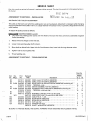 3
3
-
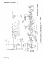 4
4
-
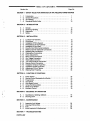 5
5
-
 6
6
-
 7
7
-
 8
8
-
 9
9
-
 10
10
-
 11
11
-
 12
12
-
 13
13
-
 14
14
-
 15
15
-
 16
16
-
 17
17
-
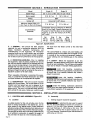 18
18
-
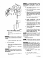 19
19
-
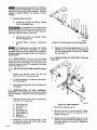 20
20
-
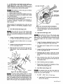 21
21
-
 22
22
-
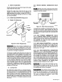 23
23
-
 24
24
-
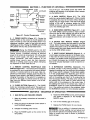 25
25
-
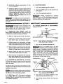 26
26
-
 27
27
-
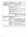 28
28
-
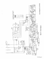 29
29
-
 30
30
-
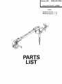 31
31
-
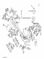 32
32
-
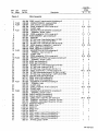 33
33
-
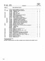 34
34
-
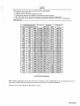 35
35
-
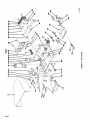 36
36
-
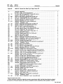 37
37
-
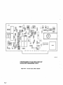 38
38
-
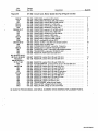 39
39
-
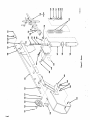 40
40
-
 41
41
-
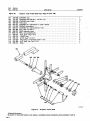 42
42
-
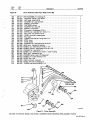 43
43
-
 44
44
-
 45
45
-
 46
46


Miller JA458805 Le manuel du propriétaire
- Catégorie
- Système de soudage
- Taper
- Le manuel du propriétaire
- Ce manuel convient également à
dans d''autres langues
- English: Miller JA458805 Owner's manual
Documents connexes
-
Miller JE753320 Le manuel du propriétaire
-
-
-
-
-
-
-
-
-