Lincoln Electric Invertec V100-S Mode d'emploi
- Catégorie
- Système de soudage
- Taper
- Mode d'emploi
Ce manuel convient également à

INVERTEC V100-S & V130-S
®
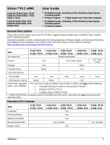
OPERATOR’S MANUAL
IM585
January, 2002
Safety Depends on You
Lincoln arc welding and cutting
equipment is designed and built
with safety in mind. However, your
overall safety can be increased by
proper installation ... and thought-
ful operation on your part. DO
NOT INSTALL, OPERATE OR
REPAIR THIS EQUIPMENT
WITHOUT READING THIS
MANUAL AND THE SAFETY
PRECAUTIONS CONTAINED
THROUGHOUT. And, most
importantly, think before you act
and be careful.
For use with machines having Code Numbers:
V100-S 10461
V130-S 10462
Date of Purchase:
Serial Number:
Code Number:
Model:
Where Purchased:
• Sales and Service through Subsidiaries and Distributors Worldwide •
Cleveland, Ohio 44117-1199 U.S.A. TEL: 216.481.8100 FAX: 216.486.1751 WEB SITE: www.lincolnelectric.com
• World's Leader in Welding and Cutting Products •
Copyright © 2002 Lincoln Global Inc.

FOR ENGINE
powered equipment.
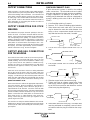
1.a. Turn the engine off before troubleshooting and maintenance
work unless the maintenance work requires it to be running.
____________________________________________________
1.b.Operate engines in open, well-ventilated
areas or vent the engine exhaust fumes
outdoors.
____________________________________________________
1.c. Do not add the fuel near an open flame
welding arc or when the engine is running.
Stop the engine and allow it to cool before
refueling to prevent spilled fuel from vaporiz-
ing on contact with hot engine parts and
igniting. Do not spill fuel when filling tank. If
fuel is spilled, wipe it up and do not start
engine until fumes have been eliminated.
____________________________________________________
1.d. Keep all equipment safety guards, covers
and devices in position and in good
repair.Keep hands, hair, clothing and tools
away from V-belts, gears, fans and all other
moving parts when starting, operating or
repairing equipment.
____________________________________________________
1.e. In some cases it may be necessary to remove safety
guards to perform required maintenance. Remove
guards only when necessary and replace them when the
maintenance requiring their removal is complete.
Always use the greatest care when working near moving
parts.
___________________________________________________
1.f. Do not put your hands near the engine fan. Do not attempt
to override the governor or idler by pushing on the throttle
control rods while the engine is running.
___________________________________________________
1.g. To prevent accidentally starting gasoline engines while
turning the engine or welding generator during maintenance
work, disconnect the spark plug wires, distributor cap or
magneto wire as appropriate.
i
SAFETY
i
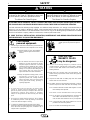
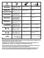
ARC WELDING CAN BE HAZARDOUS. PROTECT YOURSELF AND OTHERS FROM POSSIBLE SERIOUS INJURY OR DEATH.
KEEP CHILDREN AWAY. PACEMAKER WEARERS SHOULD CONSULT WITH THEIR DOCTOR BEFORE OPERATING.
Read and understand the following safety highlights. For additional safety information, it is strongly recommended that you
purchase a copy of “Safety in Welding & Cutting - ANSI Standard Z49.1” from the American Welding Society, P.O. Box
351040, Miami, Florida 33135 or CSA Standard W117.2-1974. A Free copy of “Arc Welding Safety” booklet E205 is available
from the Lincoln Electric Company, 22801 St. Clair Avenue, Cleveland, Ohio 44117-1199.
BE SURE THAT ALL INSTALLATION, OPERATION, MAINTENANCE AND REPAIR PROCEDURES ARE
PERFORMED ONLY BY QUALIFIED INDIVIDUALS.
WARNING
Mar ‘95
ELECTRIC AND
MAGNETIC FIELDS
may be dangerous
2.a. Electric current flowing through any conductor causes
localized Electric and Magnetic Fields (EMF). Welding
current creates EMF fields around welding cables and
welding machines
2.b. EMF fields may interfere with some pacemakers, and
welders having a pacemaker should consult their physician
before welding.
2.c. Exposure to EMF fields in welding may have other health
effects which are now not known.
2.d. All welders should use the following procedures in order to
minimize exposure to EMF fields from the welding circuit:
2.d.1.
Route the electrode and work cables together - Secure
them with tape when possible.
2.d.2. Never coil the electrode lead around your body.
2.d.3. Do not place your body between the electrode and
work cables. If the electrode cable is on your right
side, the work cable should also be on your right side.
2.d.4. Connect the work cable to the workpiece as close as
possible to the area being welded.
2.d.5. Do not work next to welding power source.
1.h. To avoid scalding, do not remove the
radiator pressure cap when the engine is
hot.
CALIFORNIA PROPOSITION 65 WARNINGS
Diesel engine exhaust and some of its constituents
are known to the State of California to cause can-
cer, birth defects, and other reproductive harm.
The engine exhaust from this product contains
chemicals known to the State of California to cause
cancer, birth defects, or other reproductive harm.
The Above For Diesel Engines
The Above For Gasoline Engines

ii
SAFETY
ii
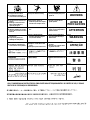
ARC RAYS can burn.
4.a. Use a shield with the proper filter and cover
plates to protect your eyes from sparks and
the rays of the arc when welding or observing
open arc welding. Headshield and filter lens
should conform to ANSI Z87. I standards.
4.b. Use suitable clothing made from durable flame-resistant
material to protect your skin and that of your helpers from
the arc rays.
4.c. Protect other nearby personnel with suitable, non-flammable
screening and/or warn them not to watch the arc nor expose
themselves to the arc rays or to hot spatter or metal.
ELECTRIC SHOCK can
kill.
3.a. The electrode and work (or ground) circuits
are electrically “hot” when the welder is on.
Do not touch these “hot” parts with your bare
skin or wet clothing. Wear dry, hole-free
gloves to insulate hands.
3.b. Insulate yourself from work and ground using dry insulation.
Make certain the insulation is large enough to cover your full
area of physical contact with work and ground.
In addition to the normal safety precautions, if welding
must be performed under electrically hazardous
conditions (in damp locations or while wearing wet
clothing; on metal structures such as floors, gratings or
scaffolds; when in cramped positions such as sitting,
kneeling or lying, if there is a high risk of unavoidable or
accidental contact with the workpiece or ground) use
the following equipment:
• Semiautomatic DC Constant Voltage (Wire) Welder.
• DC Manual (Stick) Welder.
• AC Welder with Reduced Voltage Control.
3.c. In semiautomatic or automatic wire welding, the electrode,
electrode reel, welding head, nozzle or semiautomatic
welding gun are also electrically “hot”.
3.d. Always be sure the work cable makes a good electrical
connection with the metal being welded. The connection
should be as close as possible to the area being welded.
3.e. Ground the work or metal to be welded to a good electrical
(earth) ground.
3.f.
Maintain the electrode holder, work clamp, welding cable and
welding machine in good, safe operating condition. Replace
damaged insulation.
3.g. Never dip the electrode in water for cooling.
3.h. Never simultaneously touch electrically “hot” parts of
electrode holders connected to two welders because voltage
between the two can be the total of the open circuit voltage
of both welders.
3.i. When working above floor level, use a safety belt to protect
yourself from a fall should you get a shock.
3.j. Also see Items 6.c. and 8.
FUMES AND GASES
can be dangerous.
5.a.Welding may produce fumes and gases
hazardous to health. Avoid breathing these
fumes and gases.When welding, keep
your head out of the fume. Use enough
ventilation and/or exhaust at the arc to keep
fumes and gases away from the breathing zone. When
welding with electrodes which require special
ventilation such as stainless or hard facing (see
instructions on container or MSDS) or on lead or
cadmium plated steel and other metals or coatings
which produce highly toxic fumes, keep exposure as
low as possible and below Threshold Limit Values (TLV)
using local exhaust or mechanical ventilation. In
confined spaces or in some circumstances, outdoors, a
respirator may be required. Additional precautions are
also required when welding on galvanized steel.
5.b.
Do not weld in locations near chlorinated hydrocarbon
vapors
coming from degreasing, cleaning or spraying operations.
The heat and rays of the arc can react with solvent vapors
to
form phosgene, a highly toxic gas, and other irritating
products.
5.c. Shielding gases used for arc welding can displace air and
cause injury or death. Always use enough ventilation,
especially in confined areas, to insure breathing air is safe.
5.d. Read and understand the manufacturer’s instructions for this
equipment and the consumables to be used, including the
material safety data sheet (MSDS) and follow your
employer’s safety practices. MSDS forms are available from
your welding distributor or from the manufacturer.
5.e. Also see item 1.b.
Mar ‘95

FOR ELECTRICALLY
powered equipment.
8.a. Turn off input power using the disconnect
switch at the fuse box before working on
the equipment.
8.b. Install equipment in accordance with the U.S. National
Electrical Code, all local codes and the manufacturer’s
recommendations.
8.c. Ground the equipment in accordance with the U.S. National
Electrical Code and the manufacturer’s recommendations.
CYLINDER may explode
if damaged.
7.a. Use only compressed gas cylinders
containing the correct shielding gas for the
process used and properly operating
regulators designed for the gas and
pressure used. All hoses, fittings, etc. should be suitable for
the application and maintained in good condition.
7.b. Always keep cylinders in an upright position securely
chained to an undercarriage or fixed support.
7.c. Cylinders should be located:
•Away from areas where they may be struck or subjected to
physical damage.
•A safe distance from arc welding or cutting operations and
any other source of heat, sparks, or flame.
7.d. Never allow the electrode, electrode holder or any other
electrically “hot” parts to touch a cylinder.
7.e. Keep your head and face away from the cylinder valve outlet
when opening the cylinder valve.
7.f. Valve protection caps should always be in place and hand
tight except when the cylinder is in use or connected for
use.
7.g. Read and follow the instructions on compressed gas
cylinders, associated equipment, and CGA publication P-l,
“Precautions for Safe Handling of Compressed Gases in
Cylinders,” available from the Compressed Gas Association
1235 Jefferson Davis Highway, Arlington, VA 22202.
iii
SAFETY
iii
Mar ‘95
WELDING SPARKS can
cause fire or explosion.
6.a.
Remove fire hazards from the welding area.
If this is not possible, cover them to prevent
the welding sparks from starting a fire.
Remember that welding sparks and hot
materials from welding can easily go through small cracks
and openings to adjacent areas. Avoid welding near
hydraulic lines. Have a fire extinguisher readily available.
6.b. Where compressed gases are to be used at the job site,
special precautions should be used to prevent hazardous
situations. Refer to “Safety in Welding and Cutting” (ANSI
Standard Z49.1) and the operating information for the
equipment being used.
6.c. When not welding, make certain no part of the electrode
circuit is touching the work or ground. Accidental contact
can cause overheating and create a fire hazard.
6.d. Do not heat, cut or weld tanks, drums or containers until the
proper steps have been taken to insure that such procedures
will not cause flammable or toxic vapors from substances
inside. They can cause an explosion even
though
they have
been “cleaned”. For information, purchase “Recommended
Safe Practices for the
Preparation
for Welding and Cutting of
Containers and Piping That Have Held Hazardous
Substances”, AWS F4.1 from the American Welding Society
(see address above).
6.e. Vent hollow castings or containers before heating, cutting or
welding. They may explode.
6.f.
Sparks and spatter are thrown from the welding arc. Wear oil
free protective garments such as leather gloves, heavy shirt,
cuffless trousers, high shoes and a cap over your hair. Wear
ear plugs when welding out of position or in confined places.
Always wear safety glasses with side shields when in a
welding area.
6.g. Connect the work cable to the work as close to the welding
area as practical. Work cables connected to the building
framework or other locations away from the welding area
increase the possibility of the welding current passing
through lifting chains, crane cables or other alternate cir-
cuits. This can create fire hazards or overheat lifting chains
or cables until they fail.
6.h. Also see item 1.c.

iv
SAFETY
iv
PRÉCAUTIONS DE SÛRETÉ
Pour votre propre protection lire et observer toutes les instructions
et les précautions de sûreté specifiques qui parraissent dans ce
manuel aussi bien que les précautions de sûreté générales suiv-
antes:
Sûreté Pour Soudage A L’Arc
1. Protegez-vous contre la secousse électrique:
a. Les circuits à l’électrode et à la piéce sont sous tension
quand la machine à souder est en marche. Eviter toujours
tout contact entre les parties sous tension et la peau nue
ou les vétements mouillés. Porter des gants secs et sans
trous pour isoler les mains.
b. Faire trés attention de bien s’isoler de la masse quand on
soude dans des endroits humides, ou sur un plancher
metallique ou des grilles metalliques, principalement dans
les positions assis ou couché pour lesquelles une grande
partie du corps peut être en contact avec la masse.
c. Maintenir le porte-électrode, la pince de masse, le câble
de soudage et la machine à souder en bon et sûr état
defonctionnement.
d.Ne jamais plonger le porte-électrode dans l’eau pour le
refroidir.
e. Ne jamais toucher simultanément les parties sous tension
des porte-électrodes connectés à deux machines à souder
parce que la tension entre les deux pinces peut être le
total de la tension à vide des deux machines.
f. Si on utilise la machine à souder comme une source de
courant pour soudage semi-automatique, ces precautions
pour le porte-électrode s’applicuent aussi au pistolet de
soudage.
2. Dans le cas de travail au dessus du niveau du sol, se protéger
contre les chutes dans le cas ou on recoit un choc. Ne jamais
enrouler le câble-électrode autour de n’importe quelle partie
du corps.
3. Un coup d’arc peut être plus sévère qu’un coup de soliel,
donc:
a. Utiliser un bon masque avec un verre filtrant approprié
ainsi qu’un verre blanc afin de se protéger les yeux du ray-
onnement de l’arc et des projections quand on soude ou
quand on regarde l’arc.
b. Porter des vêtements convenables afin de protéger la
peau de soudeur et des aides contre le rayonnement de
l‘arc.
c. Protéger l’autre personnel travaillant à proximité au
soudage à l’aide d’écrans appropriés et non-inflammables.
4. Des gouttes de laitier en fusion sont émises de l’arc de
soudage. Se protéger avec des vêtements de protection libres
de l’huile, tels que les gants en cuir, chemise épaisse, pan-
talons sans revers, et chaussures montantes.
5. Toujours porter des lunettes de sécurité dans la zone de
soudage. Utiliser des lunettes avec écrans lateraux dans les
zones où l’on pique le laitier.
6. Eloigner les matériaux inflammables ou les recouvrir afin de
prévenir tout risque d’incendie dû aux étincelles.
7. Quand on ne soude pas, poser la pince à une endroit isolé de
la masse. Un court-circuit accidental peut provoquer un
échauffement et un risque d’incendie.
8. S’assurer que la masse est connectée le plus prés possible
de la zone de travail qu’il est pratique de le faire. Si on place
la masse sur la charpente de la construction ou d’autres
endroits éloignés de la zone de travail, on augmente le risque
de voir passer le courant de soudage par les chaines de lev-
age, câbles de grue, ou autres circuits. Cela peut provoquer
des risques d’incendie ou d’echauffement des chaines et des
câbles jusqu’à ce qu’ils se rompent.
9. Assurer une ventilation suffisante dans la zone de soudage.
Ceci est particuliérement important pour le soudage de tôles
galvanisées plombées, ou cadmiées ou tout autre métal qui
produit des fumeés toxiques.
10. Ne pas souder en présence de vapeurs de chlore provenant
d’opérations de dégraissage, nettoyage ou pistolage. La
chaleur ou les rayons de l’arc peuvent réagir avec les vapeurs
du solvant pour produire du phosgéne (gas fortement toxique)
ou autres produits irritants.
11. Pour obtenir de plus amples renseignements sur la sûreté,
voir le code “Code for safety in welding and cutting” CSA
Standard W 117.2-1974.
PRÉCAUTIONS DE SÛRETÉ POUR
LES MACHINES À SOUDER À
TRANSFORMATEUR ET À
REDRESSEUR
1. Relier à la terre le chassis du poste conformement au code de
l’électricité et aux recommendations du fabricant. Le dispositif
de montage ou la piece à souder doit être branché à une
bonne mise à la terre.
2. Autant que possible, I’installation et l’entretien du poste seront
effectués par un électricien qualifié.
3. Avant de faires des travaux à l’interieur de poste, la debranch-
er à l’interrupteur à la boite de fusibles.
4. Garder tous les couvercles et dispositifs de sûreté à leur
place.
Mar. ‘93

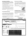
Thank You
for selecting a QUALITY product by Lincoln Electric. We want you
to take pride in operating this Lincoln Electric Company product
••• as much pride as we have in bringing this product to you!
Read this Operators Manual completely before attempting to use this equipment. Save this manual and keep it
handy for quick reference. Pay particular attention to the safety instructions we have provided for your protection.
The level of seriousness to be applied to each is explained below:
WARNING
This statement appears where the information must be followed exactly to avoid serious personal injury or
loss of life.
This statement appears where the information must be followed to avoid minor personal injury or damage to
this equipment.
CAUTION
Please Examine Car
ton and Equipment For Damage Immediatel
y
When this equipment is shipped, title passes to the purchaser upon receipt by the carrier. Consequently, Claims
for material damaged in shipment must be made by the purchaser against the transportation company at the
time the shipment is received.
Please record your equipment identification information below for future reference. This information can be
found on your machine nameplate.
Model Name & Number _____________________________________
Code & Serial Number _____________________________________
Date of Purchase _____________________________________
Whenever you request replacement parts for or information on this equipment always supply the information
you have recorded above.
vv

vi
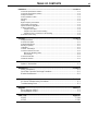
TABLE OF CONTENTS
Page
Installation.......................................................................................................................Section A
Technical Specifications V100-S..........................................................................................A-1
Technical Specifications V130-S..........................................................................................A-2
Safety Precautions. ..............................................................................................................A-3
Select Suitable Location.......................................................................................................A-3
Stacking................................................................................................................................A-3
Tilting....................................................................................................................................A-3
High Frequency Precautions................................................................................................A-3
Input Supply Connections ....................................................................................................A-3
Input Fuse and Supply Wire.................................................................................................A-3
Output Connections..............................................................................................................A-3
Output Connections ......................................................................................................A-4
Output Connection for Stick Welding ............................................................................A-4
Output and Gas Connection for TIG Welding ...............................................................A-4
Quick Disconnect Plug .........................................................................................................A-4
Operation.........................................................................................................................Section B
Safety Instructions................................................................................................................B-1
General Description..............................................................................................................B-1
Operational Features............................................................................................................B-1
Welding Capability................................................................................................................B-1
Limitations ............................................................................................................................B-1
Controls and Settings...........................................................................................................B-2
Constant Current Processes ................................................................................................B-3
Manual Arc Welding (Stick)...........................................................................................B-3
TIG Welding ..................................................................................................................B-3
Overload Protection..............................................................................................................B-3
Thermal Protection...............................................................................................................B-3
Accessories.....................................................................................................Section C
Options / Accessories............................................................................................C-1
Maintenance ....................................................................................................Section D
Safety Precautions ................................................................................................D-1
Input Filter Capacitor Discharge Procedure ..........................................................D-1
Routine Maintenance.............................................................................................D-1
Troubleshooting..............................................................................................Section E
PC Board Troubleshooting Procedures.................................................................E-1
Troubleshooting Chart...........................................................................................E-2
Diagrams..........................................................................................................Section F
Wiring Diagram V100-S.........................................................................................F-1
Wiring Diagram V130-S.........................................................................................F-2
Parts Lists........................................................................................................Appendix
V100-S...............................................................................................................P-304
V130-S...............................................................................................................P-305

-20°C to +40°C -25°C to +55°C
A-1
INSTALLATION
INVERTEC® V100-S & V130-S
A-1
Height Width Depth Weight
10.0 in. 5.4 in. 13.8 in. 11.0 lbs.
254 mm 138 mm 351 mm 5.0 Kg
PHYSICAL DIMENSIONS
INPUT Input Current
Voltage
(2)
at Rated Output Hertz
32A @ 100A OUTPUT
115V 25A @ 85A OUTPUT 50/60 Hz
20A @ 70A OUTPUT
Volts at
Duty Cycle
(1)
Amps Rated Amps
15% Duty Cycle 100 24
20% Duty Cycle 85 (20 Amp Circuit) 23.5
20% Duty Cycle 70 (15 Amp Circuit) 23
Welding Maximum Open
Current Range
Circuit Voltage
8-100 Amps 67 VDC
INPUT
RECOMMENDED INPUT CABLE AND FUSE SIZES
OUTPUT FUSE (SUPERLAG) INPUT POWER EXTENSION EXTENSION
CURRENT OR BREAKER SIZE CURRENT CORD CORD CORD
RATING (up to 50 feet) (more than 50 feet)
100A 30A 32A 30 Amp, 125V, Three Conductor Three Conductor
Three-prong plug #10 AWG (5.2 mm
2
) #8 AWG (8.2 mm
2
)
(NEMA Type 5-30P) or larger or larger
85A 25A 25A 20Amp, 125V, Three Conductor Three Conductor
Three-prong plug #12 AWG (3.3 mm
2
) #10 AWG (5.2 mm
2
)
(NEMA Type 5-20P) or larger or larger
70A 20A 20A 15 Amp, 125V, Three Conductor Three Conductor
Three-prong plug #14 AWG (2.0 mm
2
) #12 AWG (3.3 mm
2
)
(NEMA Type 5-15P) or larger or larger
SINGLE PHASE
OPERATING TEMPERATURE STORAGE TEMPERATURE
RATED OUTPUT
(1) Based on a 10 min. period.
(2) Input voltage must be within ±10% of rated value.
Technical Specifications - Invertec V100-S
OUTPUT

A-2
INSTALLATION
INVERTEC® V100-S & V130-S
A-2
-20°C to +40°C -25°C to +55°C
INPUT Input Current
Voltage
(2)
at Rated Output Hertz
25A @ 130A OUTPUT
230V 19A @ 105A OUTPUT 50/60 Hz
16A @ 90A OUTPUT
Volts at
Duty Cycle
(1)
Amps Rated Amps
20% Duty Cycle 130 25.5
60% Duty Cycle 105 24.5
100% Duty Cycle 90 24
Welding Maximum Open
Current Range Circuit Voltage
3-130 Amps 67 VDC
INPUT
RECOMMENDED INPUT CABLE AND FUSE SIZES
OUTPUT FUSE (SUPERLAG) INPUT POWER EXTENSION EXTENSION
CURRENT OR BREAKER SIZE CURRENT CORD CORD CORD
RATING (up to 50 feet) (more than 50 feet)
130A 40A 25A 50 Amp, 250V, Three Conductor Three Conductor
Three-prong plug #6 AWG (13.0 mm
2
) #4 AWG (20.7 mm
2
)
(NEMA Type 6-50P) or larger or larger
SINGLE PHASE
OPERATING TEMPERATURE STORAGE TEMPERATURE
RATED OUTPUT
(1) Based on a 10 min. period.
(2) Input voltage must be within ±10% of rated value.
Technical Specifications - Invertec V130-S
OUTPUT
Height Width Depth Weight
10.0 in. 5.4 in. 13.8 in. 11.0 lbs.
254 mm 138 mm 351 mm 5.0 Kg
PHYSICAL DIMENSIONS

A-3
INSTALLATION
INVERTEC® V100-S & V130-S
A-3
Read this entire installation section before you
start installation.
SAFETY PRECAUTIONS
ELECTRIC SHOCK can kill.
• Have an electrician install and ser-
vice this equipment.
• Turn the input power off at the fuse
box, disconnect supply lines and
allow machine to sit for five minutes
minimum to allow the power capaci-
tors to discharge before working
inside this equipment.
• Do not touch electrically hot parts.
----------------------------------------------------------------------
SELECT SUITABLE LOCATION
The Invertec will operate in harsh environments. Even
so, it is important that simple preventative measures
are followed in order to assure long life and reliable
operation.
• The machine must be located where there is free cir-
culation of clean air such that air movement in the
sides and out the sides will not be restricted.
• Dirt and dust that can be drawn into the machine
should be kept to a minimum. Failure to observe
these precautions can result in excessive operating
temperatures and nuisance shutdown.
• The machines have a protection rating of IP23. Keep
the machines dry when possible. Do not place them
on wet ground or in puddles.
STACKING
These Invertecs cannot
be stacked.
TILTING
Place the machine directly on a secure, level surface.
The machine may topple over if this procedure is not
followed.
HIGH FREQUENCY PRECAUTIONS
If possible locate the Invertec away from radio con-
trolled machinery. The normal operation of the
Invertec may adversely affect the operation of RF con-
trolled equipment, which may result in bodily injury or
damage to the equipment.
INPUT SUPPLY CONNECTIONS
Be sure the voltage, phase and frequency of the input
power is as specified on the rating plate, located on
the rear of the machine.
Both models are supplied with an input supply cable
with a molded plug. The V130-S has a 50A molded
plug and the V100-S is shipped with a molded 15A
plug and an additional 20A plug that can replace the
15A plug when necessary to achieve 85A output. To
install the supplied 20A plug: Connect the white (neu-
tral) wire under terminal clamp with silver screw, and
black (hot) wire under terminal clamp with brass
screw. Connect green wire under terminal clamp with
green screw. Tighten terminal wire clamp screws
securely. WARNING:
Failure to wire as instructed
may cause personal injury or damage to equipment.
To be installed or checked by an electrician or quali-
fied person only. In order to achieve full output from
the V100-S it is necessary to attach a 30A plug
(NEMA 5-30P).
INPUT FUSE AND SUPPLY WIRE
Refer to the Technical Specifications pages at the
beginning of this chapter for the proper fuse sizes and
supply cable sizes.
• Fuse the input circuit with recommended super lag
fuses or delay type circuit breakers.
• Install the proper fuse in the fuse holder in the main
disconnect panel.
OUTPUT CONNECTIONS
FIGURE A.1 OUTPUT CONNECTIONS
WARNING
Output
Terminals
XX
ON
OFF
XX
XX
XX
XX
XXX

A-4
INSTALLATION
INVERTEC® V100-S & V130-S
A-4
OUTPUT CONNECTIONS
Refer to Figure A.1 for the location of the output terminals.
A quick-disconnect system using Twist-Mate
TM
cable plugs is
used for the welding cable connections. The electrode and
work cables included with the machine have these plugs.
An extra plug is also included with the machine if TIG weld-
ing is desired. Refer to the relevant instructions below for
more information on connecting the machine for either of
these two welding processes.
OUTPUT CONNECTION FOR STICK
WELDING
First determine the proper electrode polarity for the elec-
trode to be used. Consult the electrode data for this infor-
mation. Then connect the output cables to the output termi-
nals corresponding to this polarity. For instance, for DC(+)
welding, connect the electrode cable (which is connected to
the electrode holder) to the “+” output terminal and the work
cable (which is connected to the work clamp) to the “-” out-
put terminal. Insert the connector with the key lining up with
the keyway, and rotate approximately 1/4 turn clockwise;
until the connection is snug. Do not over tighten.
OUTPUT AND GAS CONNECTION
FOR TIG WELDING
These units do not include a TIG torch, but one may be pur-
chased separately and used with these units to do TIG
(GTAW) welding. The Lincoln LA-9 (K859-3 or K859-7 only;
no gas valve) and LA-17V (K860-11 or K860-15 only;
includes gas valve) are recommended for use with these
machines for this purpose; however, any similar TIG torch
can be used.
If the torch to be used does not have a mating Twist-Mate
plug on the end of the power cable, the power cable must
be modified to include one. The LA-9 and LA-17V fall in this
category. Cut off the lug on the end of the power cable and
attach the extra Twist Mate plug included with the machine
to the power cable per the instructions following under
QUICK DISCONNECT PLUG.
Next connect the torch cable to the appropriate output termi-
nal on the machine. Most TIG welding is done with DC(-)
polarity. For this polarity, connect the torch plug to the “-”
output terminal on the machine. Insert the connector with
the key lining up with the keyway, and rotate approximately
1/4 turn clockwise; until the connection is snug. Do not over
tighten. Connect the work cable (which is connected to the
work clamp) to the “+” output terminal in the same way.
Finally, connect the gas hose to the gas regulator on the
cylinder of gas to be used.
The machine can easily be switched between stick and TIG
welding at any time by simply swapping the stick (electrode)
and TIG (torch) cables, and reversing the connection polari-
ty if required.
QUICK DISCONNECT PLUG
A quick disconnect system is used for the welding
cable connections. The electrode and work cables
have the plug attached, on both machines an addition-
al plug is supplied if TIG welding is to be done. The
welding plug included with the machine is designed to
accept a welding cable size of #6 to #4 (10mm
2
to
25mm
2
).
1. Cut off welding cable lug, if present.
2. Remove .75 in. (19mm) of welding cable insulation.
3. Slide rubber boot onto cable end. The boot end
may be trimmed to match the cable diameter. Use
soap or other nonpetroleum-based lubricant to
help slide the boot over the cable, if needed.
4. Cut 45-50% of the copper strands back 1/4” (6
mm).
5. Fold copper strands over cut strands and insert
into ferrule.
6. Slide the copper ferrule into the brass plug.
7. Tighten set screw to collapse copper tube. Screw
must apply pressure against welding cable. The
top of the set screw will be well below the surface
of the brass plug after tightening.
8. Slide rubber boot over brass plug. The rubber boot
must be positioned to completely cover all electri-
cal surfaces after the plug is locked into the recep-
tacle.
19 mm
.75 in.
WELDING CABLE
BOOT
TRIM, IF REQ'D
TO FIT OVER CABLE
6 mm
.25 in.
WELDING CABLE
12 mm max.
.50 in. max
WELDING CABLE
COPPER FERRULE
SET SCREW
BRASS PLUG
COPPER TUBE

B-1
OPERATION
INVERTEC® V100-S & V130-S
B-1
GENERAL DESCRIPTION
The Invertec V100-S is a light industrial 100 amp arc
welding power source and the V130-S is a light indus-
trial 130 amp arc welding power source both of which
utilize single phase input power, to produce constant
current output. The welding response of these
Invertecs has been optimized for stick (SMAW) and
TIG (GTAW). Both units are perfect for light industrial
applications where portability is important.
OPERATIONAL FEATURES
The Invertecs provide continuous total range output
current adjustment. Additionally, a “hot start” system
has been built into the welding current control, and
provides a higher striking current to assist ignition of
the arc.
WELDING CAPABILITY
The Invertec V100-S is rated at 100 amps, 15% duty
cycle (based on a 10 minute cycle). It is also rated at
85 amps, 20% duty cycle, and 70 amps, 20% duty
cycle. The Invertec V130-S is rated at 130 amps, 20%
duty cycle (based on a 10 minute cycle). It is also
rated at 105 amps, 60% duty cycle, and 90 amps,
100% duty cycle.
LIMITATIONS
The V100-S and V130-S are not recommended for
pipe thawing.
The V100-S and V130-S should not be powered from
the auxiliary power supply of an engine welder.
Special protection circuits may operate causing loss of
output.
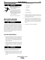
Read and understand this entire section before
operating your machine.
SAFETY INSTRUCTIONS
ELECTRIC SHOCK can kill.
• Do not touch electrically live parts such
as output terminals or internal wiring.
• Insulate yourself from the work and
ground.
• Always wear dry insulating gloves.
____________________________________
____________________________________
____________________________________
____________________________________
Only qualified personnel should operate this equip-
ment. Observe all safety information throughout this
manual.
WARNING
FUMES AND GASES
can be dangerous.
• Keep your head out of fumes.
• Use ventilation or exhaust to
remove fumes from breathing
zone.
ARC RAYS
can burn.
• Wear eye, ear and body
protection.
WELDING, CUTTING and
GOUGING SPARKS
can cause fire or explosion
• Keep flammable material away.
• Do not weld, cut or gouge on
containers that have held com-
bustibles.

B-2
OPERATION
B-2
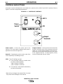
Power Switch - Controls the power input to the
machine. This rocker switch is lighted. When power is
applied to the machine the light is on.
Knob M1 - Potentiometer used to set the value of the
current required by the welding process.
LED 1 - This LED will light up when:
A) The input supply voltage is not within limits
pre-set for correct operation.
V100-S: 95VAC to 125VAC*
V130-S: 200VAC to 255VAC*
B) The machine is overheated as detected by
the internal thermostat.
* Note that input voltages that exceed 20% of nominal
may cause internal damage to the machine.
Output Terminals - These quick disconnect terminals
provide connection points for the electrode and work
cables. For positive polarity welding connect the elec-
trode cable to the positive terminal and the work cable
to the negative terminal. To weld negative polarity
reverse the electrode and work cables.
INVERTEC® V100-S & V130-S
CONTROLS AND SETTINGS
All operator controls and adjustments are located on the case front of the V100-S and V130-S machines. Refer to
Figure B.1 and the corresponding explanations.
FIGURE B.1 — CASE FRONT CONTROLS.
M1
LED 1
Power
Switch
Output
Terminals
XX
ON
OFF
XX
XX
XX
XX
XXX

B-3
OPERATION
B-3
CONSTANT CURRENT PROCESSES
MANUAL ARC WELDING (STICK)
The Invertec may be utilized as a manual DC arc
welder. The electrode cable and holder and the work
cable and clamp are included.
Excellent stick welding performance is easily achieved
with the following electrodes and current settings:
Machine Electrode Diameter Current
V100-S Fleetweld 35 3/32” Max 90 Amps
Fleetweld 180 3/32”Max 90 Amps
Fleetweld 37 3/32” Max 100 Amps
LH-78 3/32” Max 100 Amps
V130-S Fleetweld 35 1/8” Max 100 Amps
Fleetweld 180 1/8” Max 100 Amps
Fleetweld 37 1/8” Max 115 Amps
LH-78 1/8” Max 130 Amps
TIG WELDING
The Invertecs are capable of scratch start TIG weld-
ing. A TIG torch, and gas supply with regulator are
required.
OVERLOAD PROTECTION
The machine is electrically protected from producing
excessive currents. The maximum current obtainable
with the V100-S is approximately 120 amps, and that
of the V130-S is approximately 150 amps.
THERMAL PROTECTION
Thermostats protect the machine from excessive
operating temperatures. Excessive temperatures may
be caused by a lack of cooling air or operating the
machine beyond the duty cycle and output rating. If
excessive operating temperature should occur, the
thermostats will prevent output voltage or current.
Thermostats are self-resetting once the machine cools
sufficiently. If the thermostat shutdown was caused by
excessive output or duty cycle and the fan is operating
normally, the Power Switch may be left on and the
reset should occur within a 15 minute period. If the fan
is not operating or if the air flow is obstructed, this
problem must be resolved before continuing.
INVERTEC® V100-S & V130-S

C-1
ACCESSORIES
C-1
OPTIONS / ACCESSORIES
K909-1 - EH-200 Insulated electrode holder designed
for maximum operator comfort and convience.
K859-”L” - LA-9 125 amp air-cooled, lightweight, and
versatile TIG torch for thin gauge materials. Includes
two piece cable. Available in 12.5 ft. and 25 ft.
lengths.
K860-”L” - LA-17V 150 amp air-cooled compact and
durable TIG torch for thin to medium gauge materials.
Includes valve and two piece cable. Available in 12.5
ft. and 25 ft. lengths.
KP507 - Parts kit for the LA-9 torch. Kit includes back
cap, collets, collet bodies, nozzles and tungstens.
KP508 - Parts kit for the LA-17 torch. Kit includes
back cap, collets, collet bodies, nozzles and tung-
stens.
K852-25 - Twist-Mate™ plug for connecting welding
cable to output terminals. Contains one plug.
INVERTEC® V100-S & V130-S

D-1
MAINTENANCE
D-1
SAFETY PRECAUTIONS
ELECTRIC SHOCK can kill.
• Have an electrician install and ser-
vice this equipment.
• Turn the input power off at the fuse
box, disconnect supply lines and
allow machine to sit for five minutes
minimum to allow the power capaci-
tors to discharge before working
inside this equipment.
• Do not touch electrically hot parts.
----------------------------------------------------------------------
INPUT FILTER CAPACITOR
DISCHARGE PROCEDURE
The machine has internal capacitors which are
charged to a high voltage during power-on conditions.
This voltage is dangerous and must be discharged
before the machine can be serviced. Discharging is
done automatically by the machine each time the
power is switched off. However, you must allow the
machine to sit for at least 5 minutes to allow time for
the process to take place.
------------------------------------------------------------------------
ROUTINE MAINTENANCE
1. Perform the following preventive maintenance
procedures at least once every thousand hours of
use. It is good practice to keep a preventive main-
tenance record; a record tag attached to the
machine works best.
2. Remove the machine cover (requires a 3 mm hex
key) after allowing the minimum 5 minute power
off requirement to let the input capacitors dis-
charge.
Failure to observe this discharge time requirement
could result in severe electrical shock hazard.
------------------------------------------------------------------------
3. Keeping the machine clean will result in cooler
operation and higher reliability. Be sure to clean
the following areas with a low pressure air
stream.
• Printed circuit boards
• Power switch
• Fan blades
• Louvers
• Heat sink fins
• Output terminals
4. Examine capacitors for leakage or oozing. If any
leakage is noticed, take the unit to an authorized
Lincoln Field Service Shop.
5. Examine the case for breakage. Repair or
replace the case as required. Keep the case in
good condition to ensure that high voltage parts
are protected and correct spacings are main-
tained.
6. Install machine covers and fasteners.
INVERTEC® V100-S & V130-S
WARNING
WARNING
WARNING

E-1
TROUBLESHOOTING
E-1
INVERTEC® V100-S & V130-S
If for any reason you do not understand the test procedures or are unable to perform the tests/repairs safely, contact your
Local Lincoln Authorized Field Service Facility for technical troubleshooting assistance before you proceed.
CAUTION
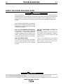
This Troubleshooting Guide is provided to
help you locate and repair possible machine
malfunctions. Simply follow the three-step
procedure listed below.
Step 1. LOCATE PROBLEM (SYMPTOM).
Look under the column labeled “PROBLEM
(SYMPTOMS)”. This column describes
possible symptoms that the machine may
exhibit. Find the listing that best describes
the symptom that the machine is exhibiting.
Step 2. POSSIBLE CAUSE.
The second column labeled “POSSIBLE
CAUSE” lists the obvious external possibili-
ties that may contribute to the machine
symptom.
Step 3. RECOMMENDED COURSE OF
ACTION
This column provides a course of action for
the Possible Cause, generally it states to
contact you local Lincoln Authorized Field
Service Facility.
If you do not understand or are unable to
perform the Recommended Course of
Action safely, contact you local Lincoln
Authorized Field Service Facility.
HOW TO USE TROUBLESHOOTING GUIDE
Service and Repair should only be performed by Lincoln Electric Factory Trained Personnel.
Unauthorized repairs performed on this equipment may result in danger to the technician and
machine operator and will invalidate your factory warranty. For your safety and to avoid
Electrical Shock, please observe all safety notes and precautions detailed throughout this
manual.
__________________________________________________________________________
WARNING

E-2
TROUBLESHOOTING
E-2
INVERTEC® V100-S & V130-S
Observe all Safety Guidelines detailed throughout this manual
If for any reason you do not understand the test procedures or are unable to perform the tests/repairs safely, contact your
Local Lincoln Authorized Field Service Facility for technical troubleshooting assistance before you proceed.
CAUTION
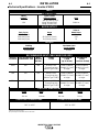
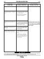
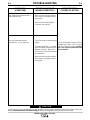
PROBLEMS
(SYMPTOMS)
POSSIBLE AREAS OF
MISADJUSTMENTS(S)
RECOMMENDED
COURSE OF ACTION
The machine is dead - no output -
no fan.
No output but the fan operates nor-
mally.
Output turns on momentarily, then
switches off.
No output - Main input fuses open,
indicating excessive current draw.
1. The input power switch must be
in the ON position.
2. Make sure the input voltage is
correct for the machine.
1. The machine may be overheated.
Check the thermal indicator light.
Wait for the machine to cool and
the thermostats to reset.
1. Check the input voltage. Make
sure the input voltage is correct
for the machine.
1. Inspect input leads for possible
shorts or grounds or mis-connec-
tions.
2. Install new fuses and reapply
power. If fuses open again, con-
sult a Lincoln Authorized Field
Service Facility.
If all recommended possible areas of
misadjustment have been checked
and the problem persists, Contact
your local Lincoln Authorized Field
Service Facility.

E-3
TROUBLESHOOTING
E-3
INVERTEC® V100-S & V130-S
Observe all Safety Guidelines detailed throughout this manual
If for any reason you do not understand the test procedures or are unable to perform the tests/repairs safely, contact your
Local Lincoln Authorized Field Service Facility for technical troubleshooting assistance before you proceed.
CAUTION
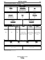
PROBLEMS
(SYMPTOMS)
POSSIBLE AREAS OF
MISADJUSTMENTS(S)
RECOMMENDED
COURSE OF ACTION
Poor welding, weld settings drift, or
output power is low.
Poor stick electrode welding
performance. The arc pops out.
1. Make sure the machine settings
are correct for the weld process
being used.
2. Make sure the input voltage is
correct for the machine.
1. Check for loose or faulty welding
cables.
2. Is the electrode DRY? Try weld-
ing with another electrode from a
different container. Make sure
you have the correct electrode for
the application.
3. Make sure the machine settings
are correct for the weld process
being used.
If all recommended possible areas of
misadjustment have been checked
and the problem persists, Contact
your local Lincoln Authorized Field
Service Facility.

F-1
DIAGRAMS
F-1
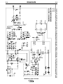
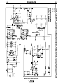
INVERTEC® V100-S & V130-S
INVERTEC V100-S
WIRING DIAGRAM
8-21-98
M18980
NOTE: This diagram is for reference only. It may not be accurate for all machines covered by this manual. The specific diagram for a particular code is pasted inside
the machine on one of the enclosure panels. If the diagram is illegible, write to the Service Department for a replacement. Give the equipment code number..
La page charge ...
La page charge ...
La page charge ...
La page charge ...
La page charge ...
-
 1
1
-
 2
2
-
 3
3
-
 4
4
-
 5
5
-
 6
6
-
 7
7
-
 8
8
-
 9
9
-
 10
10
-
 11
11
-
 12
12
-
 13
13
-
 14
14
-
 15
15
-
 16
16
-
 17
17
-
 18
18
-
 19
19
-
 20
20
-
 21
21
-
 22
22
-
 23
23
-
 24
24
-
 25
25


Lincoln Electric Invertec V100-S Mode d'emploi
- Catégorie
- Système de soudage
- Taper
- Mode d'emploi
- Ce manuel convient également à
dans d''autres langues
Documents connexes
-
Lincoln Electric EASY-MIG 180 Le manuel du propriétaire
-
-
-
-
-
-
-
-
-