Lincoln Electric MAGNUM PCT125 Manuel utilisateur
- Catégorie
- Système de soudage
- Taper
- Manuel utilisateur

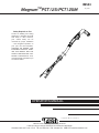
Magnum PCT125/PCT125M
OPERATOR’S MANUAL
IM543
July, 2004
Safety Depends on You
Lincoln arc welding and cutting
equipment is designed and built
with safety in mind. However,
your overall safety can be
increased by proper installation
... and thoughtful operation on
your part. DO NOT INSTALL,
OPERATE OR REPAIR THIS
EQUIPMENT WITHOUT READ-
ING THIS MANUAL AND THE
SAFETY PRECAUTIONS CON-
TAINED THROUGHOUT. And,
most importantly, think before you
act and be careful.
3
3
4
C
E
I
I
E
C
6
0
9
7
4
-
7
A
-
1
4
1
™
• Sales and Service through Subsidiaries and Distributors Worldwide •
Cleveland, Ohio 44117-1199 U.S.A. TEL: 216.481.8100 FAX: 216.486.1751 WEB SITE: www.lincolnelectric.com
• World's Leader in Welding and Cutting Products •
Copyright © 2004 Lincoln Global Inc.

i
SAFETY
i
PROTECT YOURSELF AND OTHERS FROM POSSIBLE SERIOUS INJURY OR DEATH. KEEP CHILDREN
AWAY. PACEMAKER WEARERS SHOULD CONSULT WITH THEIR DOCTOR BEFORE OPERATING.
Read and understand the following safety highlights. For additional safety information it is strongly recommended that you pur-
chase a copy of “Safety in Welding & Cutting - ANSI Standard Z49.1” from the American Welding Society, P.O. Box 351040,
Miami, Florida 33135 or CSA Standard W117.2.
BE SURE THAT ALL INSTALLATION, OPERATION, MAINTENANCE, AND REPAIR PROCEDURES ARE PER-
FORMED ONLY BY QUALIFIED INDIVIDUALS.
CUTTING SPARKS can
cause fire or explosion.
4.a..Remove fire hazards from the plasma cutting
or gouging area. If this is not possible, cover
them to prevent the cutting or gouging sparks
from starting a fire. Remember that welding
sparks and hot materials from plasma cutting or
gouging can easily go through small cracks and openings to
adjacent areas. Avoid cutting or gouging near hydraulic lines.
Have a fire extinguisher readily available.
4.b. Where compressed gases are to be used at the job site, spe-
cial precautions should be used to prevent hazardous situa-
tions. Refer to “Safety in Welding and Cutting” (ANSI Standard
Z49.1) and the operating information for the equipment being
used.
4.c. When not cutting or gouging, make certain no part of the elec-
trode circuit is touching the work or ground. Accidental contact
can cause overheating and create a fire hazard.
4.d. Do not cut or gouge tanks, drums or containers until the prop-
er steps have been taken to insure that such procedures will
not cause flammable or toxic vapors from substances inside.
They can cause an explosion even though they have been
“cleaned.” For information purchase “Recommended Safe
Practices for the Preparation for Welding and Cutting of
Containers and Piping That Have Held Hazardous
Substances”, AWS F4.1 from the American Welding Society
(see address above).
4.e. Vent hollow castings or containers before heating, cutting or
gouging. They may explode.
4.f. Do nor fuel engine driven equipment near area where plasma
cutting or gouging.
ARC RAYS can burn.
2.a. Use safety glasses and a shield with the prop-
er filter and cover plates to protect your eyes from
sparks and the rays of the arc when performing or
observing plasma arc cutting or gouging.
Glasses,headshield and filter lens should conform
to ANSI Z87. I standards.
2.b. Use suitable clothing including gloves made from durable
flame-resistant material to protect your skin and that of your
helpers from the arc rays.
2.c. Protect other nearby personnel with suitable non-flammable
screening and/or warn them not to watch the arc nor expose
themselves to the arc rays or to hot spatter or metal.
ELECTRIC SHOCK can kill.
1.a. The electrode and work (or ground) circuits
are electrically “hot” when the power source is on.
Do not touch these “hot” parts with your bare skin
or wet clothing. Wear dry, hole-free gloves to insu-
late hands.
1.b. When the power source is operating voltages
in excess of 250 volts are produced. This creates the poten-
tial for serious electrical shock - potentially even fatal.
1.c. Insulate yourself from work and ground using dry insulation.
When cutting or gouging in damp locations, on metal frame-
work such as floors, gratings or scaffolds and when in posi-
tions such as sitting or lying, make certain the insulation is
large enough to cover your full area of physical contact with
work and ground.
1.d. Always be sure the work cable makes a good electrical con-
nection with the metal being cut or gouged. The connection
should be as close as possible to the area being cut or
gouged.
1.e. Ground the work or metal to be cut or gouged to a good elec-
trical (earth) ground.
1.f. Maintain the plasma torch, cable and work clamp in good, safe
operating condition. Replace damaged insulation.
1.g. Never dip the torch in water for cooling or plasma cut or gouge
in or under water.
1.h. When working above floor level, protect yourself from a fall
should you get a shock.
1.i. Operate the pilot arc with caution. The pilot arc is capable of
burning the operator, others or even piercing safety clothing.
1.j. Also see Items 4c and 6.
WARNING
PLASMA CUTTING or GOUGING can be hazardous.
FUMES AND GASES
can be dangerous.
3.a. Plasma cutting or gouging may produce
fumes and gases hazardous to health. Avoid
breathing these fumes and gases.When cutting
or gouging, keep your head out of the fumes. Use
enough ventilation and/or exhaust at the arc to
keep fumes and gases away from the breathing zone. When
cutting or gouging on lead or cadmium plated steel and
other metals or coatings which produce highly toxic
fumes keep exposure as low as possible and below
Threshold Limit Values (TLV) using local exhaust or
mechanical ventilation. In confined spaces or in some
circumstances, outdoors, a respirator may be required.
Additional precautions are also required when welding
on galvanized steel.
3.b. Do not use plasma arc cutting or gouging in locations near
chlorinated hydrocarbon vapors coming from degreasing,
cleaning or spraying operations. The heat and rays of the arc
can react with solvent vapors to form phosgene, a highly toxic
gas, and other irritating products.
3.c. Gases used for plasma cutting and gouging can displace air
and cause injury or death. Always use enough ventilation,
especially in confined areas, to insure breathing air is safe.
3.d. Read and understand the manufacturer’s instructions for this
equipment and the consumables to be used, including the
material safety data sheet (MSDS) and follow your employ-
er’s safety practices.

ii
SAFETY
ii
FOR ELECTRICALLY
powered equipment.
6.a. Turn off input power using the disconnect
switch at the fuse box before working on the
equipment.
6.b. Install equipment in accordance with the U.S. National
Electrical Code, all local codes and the manufacturer’s rec-
ommendations.
6.c. Ground the equipment in accordance with the U.S. National
Electrical Code and the manufacturer’s recommendations.
CYLINDER may explode
if damaged.
5.a. Use only compressed gas cylinders contain-
ing the correct gas for the process used and
properly operating regulators designed for the
gas and pressure used. All hoses, fittings, etc.
should be suitable for the application and maintained in good
condition.
5.b. Always keep cylinders in an upright position securely chained
to an undercarriage or fixed support.
5.c. Cylinders should be located:
• Away from areas where they may be struck or subjected to
physical damage.
• A safe distance from plasma cutting or gouging, arc weld-
ing operations and any other source of heat, sparks,
or flame.
5.d. Never allow any part of the electrode, torch or any other elec-
trically “hot” parts to touch a cylinder.
5.e. Keep your head and face away from the cylinder valve outlet
when opening the cylinder valve.
5.f. Valve protection caps should always be in place and hand
tight except when the cylinder is in use or connected for use.
5.g. Read and follow the instructions on compressed gas cylin-
ders, associated equipment, and CGA publication P-l,
“Precautions for Safe Handling of Compressed Gases in
Cylinders,”available from the Compressed Gas Association
1235 Jefferson Davis Highway, Arlington, VA 22202.
Apr. ‘93
ELECTRIC AND MAGNETIC FIELDS
may be dangerous
8.a. Electric current flowing through any conduc-
tor causes localized Electric and Magnetic Fields
(EMF). Cutting or gouging current creates EMF
fields around torch cables and cutting machines.
8.b. EMF fields may interfere with some pace-
makers, so operators having a pacemaker should consult
their physician before cutting or gouging.
8.c. Exposure to EMF fields during cutting or gouging may have
other health effects which are now not known.
8d. All operators should use the following procedures in order to
minimize exposure to EMF fields from the cutting or gouging
circuit:
8.d.1. Route the torch and work cables together - Secure
them with tape when possible.
8.d.2. Never coil the torch cable around your body.
8.d.3. Do not place your body between the torch and
work cables. If the torch cable is on your right side,
the work cable should also be on your right
side.
8.d.4. Connect the work cable to the workpiece as close as
possible to the area being cut or gouged.
8.d.5. Do not work next to cutting power source.
4.g. Sparks and spatter are thrown from the plasma arc. Wear safe-
ty glasses, ear protection and oil free protective garments such
as leather gloves, heavy shirt, cuffless trousers, high shoes
and a cap over your hair. Wear ear plugs when cutting or goug-
ing out of position or in confined places. Always wear safety
glasses with side shields when in a cutting or gouging area.
4.h. Connect the work cable to the work as close to the cutting or
gouging area as practical. Work cables connected to the build-
ing framework or other locations away from the cutting or goug-
ing area increase the possibility of the current passing through
lifting chains, crane cables or other alternate circuits. This can
create fire hazards or overheat lifting chains or cables until they
fail.
PLASMA ARC can injure.
7.a. Keep your body away from nozzle and
plasma arc.
7.b. Operate the pilot arc with caution. The pilot arc is capable of
burning the operator, others or even piercing safety clothing.

NOTES

iv
SAFETY
iv
PRÉCAUTIONS DE SÛRETÉ
Pour votre propre protection lire et observer toutes les instructions
et les précautions de sûreté specifiques qui parraissent dans ce
manuel aussi bien que les précautions de sûreté générales suiv-
antes:
Sûreté Pour Soudage A L’Arc
1. Protegez-vous contre la secousse électrique:
a. Les circuits à l’électrode et à la piéce sont sous tension
quand la machine à souder est en marche. Eviter toujours
tout contact entre les parties sous tension et la peau nue
ou les vétements mouillés. Porter des gants secs et sans
trous pour isoler les mains.
b. Faire trés attention de bien s’isoler de la masse quand on
soude dans des endroits humides, ou sur un plancher met-
allique ou des grilles metalliques, principalement dans
les positions assis ou couché pour lesquelles une grande
partie du corps peut être en contact avec la masse.
c. Maintenir le porte-électrode, la pince de masse, le câble de
soudage et la machine à souder en bon et sûr état defonc-
tionnement.
d.Ne jamais plonger le porte-électrode dans l’eau pour le
refroidir.
e. Ne jamais toucher simultanément les parties sous tension
des porte-électrodes connectés à deux machines à souder
parce que la tension entre les deux pinces peut être le total
de la tension à vide des deux machines.
f. Si on utilise la machine à souder comme une source de
courant pour soudage semi-automatique, ces precautions
pour le porte-électrode s’applicuent aussi au pistolet de
soudage.
2. Dans le cas de travail au dessus du niveau du sol, se protéger
contre les chutes dans le cas ou on recoit un choc. Ne jamais
enrouler le câble-électrode autour de n’importe quelle partie du
corps.
3. Un coup d’arc peut être plus sévère qu’un coup de soliel, donc:
a. Utiliser un bon masque avec un verre filtrant approprié ainsi
qu’un verre blanc afin de se protéger les yeux du rayon-
nement de l’arc et des projections quand on soude ou
quand on regarde l’arc.
b. Porter des vêtements convenables afin de protéger la peau
de soudeur et des aides contre le rayonnement de l‘arc.
c. Protéger l’autre personnel travaillant à proximité au
soudage à l’aide d’écrans appropriés et non-inflammables.
4. Des gouttes de laitier en fusion sont émises de l’arc de
soudage. Se protéger avec des vêtements de protection libres
de l’huile, tels que les gants en cuir, chemise épaisse, pan-
talons sans revers, et chaussures montantes.
5. Toujours porter des lunettes de sécurité dans la zone de
soudage. Utiliser des lunettes avec écrans lateraux dans les
zones où l’on pique le laitier.
6. Eloigner les matériaux inflammables ou les recouvrir afin de
prévenir tout risque d’incendie dû aux étincelles.
7. Quand on ne soude pas, poser la pince à une endroit isolé de
la masse. Un court-circuit accidental peut provoquer un
échauffement et un risque d’incendie.
8. S’assurer que la masse est connectée le plus prés possible de
la zone de travail qu’il est pratique de le faire. Si on place la
masse sur la charpente de la construction ou d’autres endroits
éloignés de la zone de travail, on augmente le risque de voir
passer le courant de soudage par les chaines de levage,
câbles de grue, ou autres circuits. Cela peut provoquer des
risques d’incendie ou d’echauffement des chaines et des
câbles jusqu’à ce qu’ils se rompent.
9. Assurer une ventilation suffisante dans la zone de soudage.
Ceci est particuliérement important pour le soudage de tôles
galvanisées plombées, ou cadmiées ou tout autre métal qui
produit des fumeés toxiques.
10. Ne pas souder en présence de vapeurs de chlore provenant
d’opérations de dégraissage, nettoyage ou pistolage. La
chaleur ou les rayons de l’arc peuvent réagir avec les vapeurs
du solvant pour produire du phosgéne (gas fortement toxique)
ou autres produits irritants.
11. Pour obtenir de plus amples renseignements sur la sûreté, voir
le code “Code for safety in welding and cutting” CSA Standard
W 117.2-1974.
PRÉCAUTIONS DE SÛRETÉ POUR
LES MACHINES À SOUDER À
TRANSFORMATEUR ET À
REDRESSEUR
1. Relier à la terre le chassis du poste conformement au code de
l’électricité et aux recommendations du fabricant. Le dispositif
de montage ou la piece à souder doit être branché à une
bonne mise à la terre.
2. Autant que possible, I’installation et l’entretien du poste seront
effectués par un électricien qualifié.
3. Avant de faires des travaux à l’interieur de poste, la debranch-
er à l’interrupteur à la boite de fusibles.
4. Garder tous les couvercles et dispositifs de sûreté à leur place.
Mar. ‘93

PLASMA TORCH
vv
Thank You
for selecting a QUALITY product by Lincoln Electric. We want you
to take pride in operating this Lincoln Electric Company product •••
as much pride as we have in bringing this product to you!
Read this Operators Manual completely before attempting to use this equipment. Save this manual and keep it
handy for quick reference. Pay particular attention to the safety instructions we have provided for your protection.
The level of seriousness to be applied to each is explained below:
WARNING
This statement appears where the information must be followed exactly to avoid serious personal injury or
loss of life.
This statement appears where the information must be followed to avoid minor personal injury or damage to
this equipment.
CAUTION
Please Examine Carton and Equipment For Damage Immediately
When this equipment is shipped, title passes to the purchaser upon receipt by the carrier. Consequently, Claims
for material damaged in shipment must be made by the purchaser against the transportation company at the time
the shipment is received.
Please record your equipment identification information below for future reference. This information can be found
on your machine nameplate.
Product _________________________________________________________________________________
Model Number ___________________________________________________________________________
Code Number or Date Code_________________________________________________________________
Serial Number____________________________________________________________________________
Date Purchased___________________________________________________________________________
Where Purchased_________________________________________________________________________
Whenever you request replacement parts or information on this equipment, always supply the information you
have recorded above. The code number is especially important when identifying the correct replacement parts.
On-Line Product Registration
- Register your machine with Lincoln Electric either via fax or over the Internet.
• For faxing: Complete the form on the back of the warranty statement included in the literature packet
accompanying this machine and fax the form per the instructions printed on it.
• For On-Line Registration: Go to our
WEB SITE at www.lincolnelectric.com. Choose “Quick Links” and then
“Product Registration”. Please complete the form and submit your registration.

PLASMA TORCH
TABLE OF CONTENTS
Page
SPECIFICATION SUMMARY........................................................................................................A-1
GENERAL DESCRIPTION............................................................................................................A-2
INSTALLATION..............................................................................................................................A-2
OPERATION..................................................................................................................................B-1
MAINTENANCE ............................................................................................................................C-1
TORCH HEAD AND CABLE REPLACEMENT.......................................................................C-2
TROUBLESHOOTING ..................................................................................................................D-1
PARTS PAGES ..................................................................................................................P210-C,-G
vivi

A-1
INSTALLATION
PLASMA TORCH
A-1
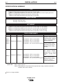
SPECIFICATIONS SUMMARY
K880-1 PCT125 Hand-held Plasma Torch with 25 ft. (7.6m) cable
K880-2 PCT125 Hand-held Plasma Torch with 50 ft. (15.2m) cable
K880-3 PCT125M Plasma Machine Torch with 50 ft (15.2m) cable and 24 and 32 pitch gear racks
K880-4 PCT125M Robotic Plasma Torch with 50 ft (15.2m) cable
K880-5 PCT125 Hand-held Plasma Torch with 25 ft. (7.6m) cable
Torch Electrode Swirl Ring Nozzle Cup
K880-1 KP2042-1B1 .055" (1.4 mm) orifice
K880-2 KP2042-2B1 .067" (1.7 mm) orifice
K880-3 KP2042-3B1 .075" (1.9 mm) orifice
K880-4
KP2042-4B1 .118" (3.0 mm) orifice for gouging
KP2042-1B1 .055" (1.4 mm) orifice
K880-5 KP2042-2B1 .067" (1.7 mm) orifice
KP2042-3B1 .075" (1.9 mm) orifice
KP2042-4B1 .118" (3.0 mm) orifice for gouging
125 Amps, 60% Duty Cycle
100 Amps, 100% Duty Cycle
K880-1 PCT125 Hand-held Plasma Torch with 25 ft. (7.6m) cable, 11.5 lbs (5.2 kg)
K880-2 PCT125 Hand-held Plasma Torch with 50 ft. (15.2m) cable, 21.5 lbs (9.8 kg)
K880-3 PCT125M Plasma Machine Torch with 50 ft. (15.2m) cable, 21.5 lbs (9.8 kg)
K880-4 PCT125M Robotic Plasma Torch with 50 ft. (15.2m) cable, 21.5 lbs (9.8 kg)
K880-5 PCT125 Hand-held Plasma Torch with 25 ft. (7.6m) cable, 12.0 lbs. (5.4 kg)
KP2045-1 Shield Cup with
optional KP2046-1 standoff
guide or optional KP2047-1
gouging attachment.
S19974 Contact Cutting
Attachment with required
S19973 Contact Cutting
Insulator.
Option Kits K881-1 Spare Parts Kit
K952-1 Robotic/Machine Torch Retrofit Kit (required when using a machine torch with a
machine code 10119 or below.)
Torch is no longer available.
OUTPUT RATING
NET WEIGHT
TORCH COMPONENTS
TYPE
KP2043-1B1
KP2043-1B1
KP2044-1
KP2044-1
KP2045-1 or -2 Shield Cup
with optional KP2046-1
standoff guide or optional
KP2047-1 gouging attach-
ment.
S19974 Contact Cutting
Attachment with required
S19973 or S19973-1
Contact Cutting Insulator.

A-2
INSTALLATION
PLASMA TORCH
A-2
GENERAL DESCRIPTION
The Magnum PCT125/PCT125M plasma torches have
been designed for use on a Pro-Cut 125. All of the
torches are single gas, air-cooled. The torches are
supplied factory mounted to the Pro-Cut or can be
bought as individual units.
The hand-held torch is available only with a 70° head.
It is supplied with either a 25 ft (7.6m) or 50 ft (15.2m)
cable.
Two styles of mechanized torches are available. The
robotic torch features an 8” (203mm) long, 1-5/8“
(42.3mm) diameter barrel. The machine torch has a
12” (305mm) long, 1-3/8“ (34.9mm) diameter barrel
with a 32 pitch gear rack. The 32 pitch gear rack can
be easily substituted with a 24 pitch gear rack which is
included with the machine torch. The mechanized
torches are offered only with 50 ft (15.2m) cables.
Included with all mechanized torches is a 25 ft (7.6m)
arc starter switch assembly for triggering the Pro-Cut
without the use of an interface kit.
CNC or Robotic interface kits are available as a field
installed option for those customer desiring automated
plasma cutting. The kits provide remote triggering,
remote output control and give a signal once a cutting
arc has been established.
All of the plasma torches use the same consumables.
In order to operate, a torch must have an electrode,
swirl ring, nozzle and shield cup. There are three cut-
ting nozzles available to give optimum arc perfor-
mance at low, medium and high output. A gouging
nozzle is also available. Drag cutting can be done by
placing a wire standoff guide on to the shield cup or by
using a contact cutting attachment and contact cutting
insulator in place of the shield cup.
Operation from bottled compressed air or gas cylinders
is not recommended due to the large volume of gas
required for plasma cutting.
INSTALLATION
ELECTRIC SHOCK can kill.
• Only qualified personnel should per-
form this installation.
• Turn the input power OFF at the dis-
connect switch or fuse box before
working on this equipment.
• Do not touch electrically hot parts.
• Do not operate with covers removed.
TOOLS REQUIRED:
5/16” nut driver
5/8” open end wrench
channel locks
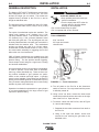
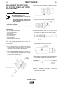
FIGURE A.1 — Torch Connections.
A. Turn off power to the Pro-Cut at the disconnect
switch or fuse box. Do not proceed until the power
is definitely turned off.
B. Using a 5/16” nut driver, remove the sheet metal
screw which holds the access door shut on the right
side of the Pro-Cut. Open the door.
C. To remove a torch from the Pro-Cut, refer to Figure
A.1 and do the following:
1. Separate the two molex connectors from torch to
the Pro-Cut.
2. Using a 5/8" open end wrench, loosen and
unscrew the nut securing the gas tube to the
bulkhead union.
WARNING

A-3
INSTALLATION
PLASMA TORCH
A-3
3. Unscrew the wing nut and remove the pilot lead
of the torch cable from the pilot stud.
4. Loosen the strain relief cap using channel locks
if necessary. Then loosen and unscrew the
strain relief from the conduit lock nut.
5. Slide the cable through the conduit lock nut and
out through the hole in the case front.
D. To assemble a torch to the Pro-Cut:
1. Slide the end of the cable through the hole in the
case front. Then slide the conduit lock nut over
the end of the cable.
2. With a 5/8" wrench tighten the fitting at the end of
the gas tube onto the bulkhead union.
3. Place the ring lug of the pilot leads from the cable
over the pilot stud. Place the wing nut on the
pilot stud and tighten.
4. Connect the two molex connectors from the
torch to the molex connectors in the Pro-Cut.
5. Loosen the cap on the strain relief. Slide the
strain relief into the hole in the case front. Screw
the conduit lock nut on to the strain relief and
tighten the strain relief with channel locks. Hand
tighten the strain relief cap and then tighten the
cap an additional 1/2 turn with channel locks.
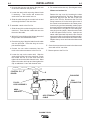
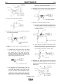
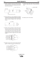
6. For mechanized torches only: (See diagram below)
Without an interface kit
Remove the top cover by loosening the sheet
metal screws with a 5/16" nut driver. Remove the
black hole plug from the left side of the front
panel of the Pro-Cut. Disconnect the Pro-Cut's
wiring harness at J5 in the lower right corner of
the control board mounted on the center panel.
Insert the plug and lead assembly (molex jumper
that came with the mechanized torch) into J5 on
the control board. Plug the Pro-Cut’s wiring har-
ness plug into the jumper. Mount the strain relief
to the front panel of the Pro-Cut. Insert the arc
starter cable (terminals first) into the Pro-Cut and
connect the cable to the plug and lead assembly.
Tighten the strain relief onto the arc starter cable.
Replace the top cover and insert the sheet metal
screws.
CONTROL P.C.
BOARD
J5
PLUG &
LEAD ASSEMBLY
MAIN
HARNESS
ARC STRIKING
CABLE
BOX
CONNECTOR
BULKHEAD
E. Close the access door and screw in the sheet metal
screw with a 5/16" nut driver.
F. Restore power to the Pro-Cut.

B-1
OPERATION
B-1
OPERATION
Refer to your Pro-Cut operator’s manual for complete
operating information.
When plasma cutting, it is necessary to wear
proper eye, head and body protection.
A. Connect the work lead to the material to be cut.
B. Assemble an electrode, swirl ring, nozzle and shield
cup on the torch.
C. Turn the Pro-Cut “ON” with the power switch on the
front of the Pro-Cut.
D. Flip the Run/Purge switch to PURGE. Adjust the
regulator until the pressure gage reads 55-65 psi
(379-448 kPa.) Flip the Run/Purge switch to RUN.
Air will continue to flow for 60 seconds because the
Pro-Cut will be in post flow.
E. Adjust the output to the desired level. Refer to the
appropriate Lincoln Process and Procedure
Guidelines for recommended output, standoff, noz-
zle and cutting technique for your application.
F. Activate the trigger.
• If the air was not already flowing, the Pro-Cut will
allow the air to flow for two seconds before the
pilot arc is started. This is called PREFLOW.
• If the trigger was activated during the first twelve
seconds of postflow then a pilot arc will start
instantly.
• To start an arc after the first twelve seconds of
postflow it will be necessary to perform a double
trigger pull consisting of activating, releasing and
activating the triggering within a one second
period.
G Bring the pilot arc close to the material to be cut.
Once the torch is about 1/8" to 1/4" (3 mm to 6 mm)
away from the work piece the arc will automatically
transfer to the work and the Pro-Cut will regulate
output to the setting on the dial (or to the signal from
an interface kit.) It is best to minimize the pilot arc
time in order to prolong consumable life. Starting at
the edge of the work piece instead of piercing the
material increases consumable life also.
H. Release the trigger when the cut is complete. Air
will continue to flow for 60 seconds to cool the torch.
This is called POSTFLOW.
PLASMA TORCH
WARNING

C-1
MAINTENANCE
C-1
MAINTENANCE
ELECTRIC SHOCK CAN KILL
• Only qualified personnel should per-
form this installation.
• Turn the input power OFF at the dis-
connect switch or fuse box before
working on this equipment.
• Do not touch electrically hot parts.
• Do not operate with covers removed.
Keep the work area clean and free of combustible
materials. Prevent debris and objects from obstructing
air flow around the Pro-Cut.
Every few months, blow the dust off the air intakes and
louvers with compressed air.
Check the filter elements every several months to see
if they are clogged (weekly in very dirty environments).
Replace if necessary.
Inspect the cable periodically for any slits or puncture
marks in the cable jacket. Replace if necessary.
Check to make sure that nothing is crushing the cable
and blocking the flow of air through the air tube inside.
Also, check for kinks in the cable and relieve any so
as not to restrict the flow of air to the torch.
Replace the electrode when the pit in the center of the
electrode is deeper than .050" (1.3 mm) or when the
copper portion is severely distorted.
Replace the nozzle when the orifice is no longer round
or when the inside surface is covered with scale.
Green colored arcs indicate the electrode and/or
nozzle are worn and need to be replaced.
PLASMA TORCH
WARNING

C-2
MAINTENANCE
C-2
REPLACEMENT INSTRUCTIONS
FOR PCT125M CABLE AND TORCH
HEAD ASSEMBLY
ELECTRIC SHOCK can kill.
• Turn the input power off to the Pro-
Cut using the disconnect switch at
the fuse box before attempting to
replace either the torch head or the
cable assembly.
• Only qualified personnel should install, service
or use this equipment.
• Read instructions thoroughly before beginning.
Tools Required:
two 5/8" open end wrenches
7/16" open end wrench
channel locks
roll of electrical tape
5/64" Allen wrench
9/64" Allen wrench
small flat bladed screwdriver
NOTE: The pictures illustrate the robotic torch. The
procedure for replacing components on the machine
torch is similar.
1. Be sure power is OFF to the machine by using the
disconnect switch at the fuse box. Do not proceed
until power to the machine is disconnected.
2. Use a small flat bladed screwdriver to relieve ten-
sion on the hose clamp around the boot. Remove
the hose clamp from the torch.
3. Loosen the strain relief cap using channel locks if
necessary.
4. Remove the socket head screws holding the strain
relief to the barrel with a 9/64" Allen wrench.
5. Slide the boot, strain relief cap and strain relief as
a complete unit about one foot along the cable.
6. Use a 5/64" Allen wrench to remove the set screws
securing the barrel to the torch head.
7. Slide the barrel and insulating tube along the cable
to reveal the cable-to-torch head connections.
8. Using a flat bladed screwdriver, loosen and
remove the screws securing the leads from the
cable to the torch head.
PLASMA TORCH
WARNING

C-3
MAINTENANCE
C-3
9. Untape and remove the insulation.
10. Separate the torch head from the cable using two
5/8" open end wrenches.
11. Replace the torch head or cable assembly as fol-
lows:
a. To replace the torch head, remove the fitting
from the old torch head by using a 5/8" open
end wrench and a 7/16" open end wrench.
Discard the old torch head and obtain a new
torch head. Place the fitting on the new torch
head and tighten with the wrenches.
b. For replacing the cable assembly, slide the
insulating tube, barrel, strain relief and boot off
of the old cable. Obtain a new cable and dis-
card the old cable. If the boot becomes sepa-
rated from the strain relief, insert the boot under
the fingers of the strain relief before sliding the
parts onto the new cable. Slide the following
parts on to the new cable in this order: Boot and
strain relief, barrel, insulating tube.
12. Assembly the torch head to the cable and tighten
the fittings using two 5/8" open end wrenches.
13. Attach the insulation sheet as follows:
a. Use a piece of electrical tape to attach the insu-
lation to the fitting. Center the insulation so that
all of the fittings and the hose clamp will be
completely covered.
b. Tightly wrap the insulation sheet around the fit-
tings and underneath the stem for the pilot con-
nection of the torch head. Secure the insulation
in place with two pieces of electrical tape.
14. Assemble the leads from the cable to the torch
head per the following diagram. It is not important
which side of the torch head the red and the white
lead mount.
PLASMA TORCH

C-4
MAINTENANCE
C-4
15. Slide the insulating tube over the cable and torch
head connections to the back of the torch head
and align the holes in the insulating tube with the
holes in the torch head.
16. Slide the barrel over the insulating tube, aligning
the holes in the barrel with the holes in the insulat-
ing tube. Secure the barrel and tube in place with
the set screws and tighten with a 5/64" Allen
wrench.
17. Slide the strain relief with the cable boot into the
barrel. Do not allow the boot to slip out from under-
neath the fingers of the strain relief. Align the holes
in the strain relief with the holes in the barrel.
Secure the barrel to the strain relief with the sock-
et head cap screws and tighten with a 9/64" Allen
wrench.
18. Tighten the strain relief cap hand tight and then
tighten an additional half-turn with channel locks.
19. Place the hose clamp around the boot. Assemble
the hose clamp such that it is snug around the
boot.
20. Restore power to the machine.
PLASMA TORCH

PLASMA TORCH
D-1
TROUBLESHOOTING
D-1
If for any reason you do not understand the test procedures or are unable to perform the tests/repairs safely, contact your Local
Lincoln Authorized Field Service Facility for technical troubleshooting assistance before you proceed.
CAUTION
This Troubleshooting Guide is provided to help you
locate and repair possible machine malfunctions.
Simply follow the three-step procedure listed below.
Step 1. LOCATE PROBLEM (SYMPTOM).
Look under the column labeled “PROBLEM (SYMP-
TOMS)”. This column describes possible symptoms
that the machine may exhibit. Find the listing that best
describes the symptom that the machine is exhibiting.
Step 2. POSSIBLE CAUSE.
The second column labeled “POSSIBLE CAUSE” lists
the obvious external possibilities that may contribute to
the machine symptom.
Step 3. RECOMMENDED COURSE OF ACTION
This column provides a course of action for the
Possible Cause, generally it states to contact your
local Lincoln Authorized Field Service Facility.
If you do not understand or are unable to perform the
Recommended Course of Action safely, contact your
local Lincoln Authorized Field Service Facility.
HOW TO USE TROUBLESHOOTING GUIDE
Service and Repair should only be performed by Lincoln Electric Factory Trained Personnel.
Unauthorized repairs performed on this equipment may result in danger to the technician and machine
operator and will invalidate your factory warranty. For your safety and to avoid Electrical Shock, please
observe all safety notes and precautions detailed throughout this manual.
__________________________________________________________________________
WARNING

D-2
TROUBLESHOOTING
D-2
PLASMA TORCH
Observe all Safety Guidelines detailed throughout this manual
If for any reason you do not understand the test procedures or are unable to perform the tests/repairs safely, contact your Local
Lincoln Authorized Field Service Facility for technical troubleshooting assistance before you proceed.
CAUTION
FUNCTION PROBLEMS
PROBLEMS
(SYMPTOMS)
POSSIBLE CAUSE
RECOMMENDED
COURSE OF ACTION
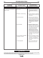
The torch does not start when the
trigger is pulled
a. Blown fuse
b. Electrode or nozzle missing
c. Torch misconnected
d. Cable damaged
e. Torch connections assembled
improperly or shorted
f. Pro-Cut inoperative
a. Make sure all three phases are
present and the Pro-Cut is
reconnected for the proper volt-
age.
b. Properly assemble an electrode,
swirl ring, nozzle and shield cup
on the torch.
c. Make sure the pilot lead from
the torch cable is connected to
the pilot stud inside the Pro-Cut.
Verify that the fitting at the end
of the gas tube is connected to
the bulkhead union inside the
Pro-Cut.
d. Examine the cable for cuts or
punctures. Make sure there is
continuity from the nozzle at the
torch head to the ring lug at the
end of the pilot lead at the
machine end of the cable.
Make sure there is continuity
from the electrode at the torch
head to the fitting at the end of
the gas tube at the machine end
of the cable. replace any dam-
aged cable.
e. Remove the handles (or barrel)
of the torch and examine all the
connections. Pay attention to
lugs crimped on insulation, bro-
ken leads.
f. Refer to the troubleshooting
guide for the Pro-Cut 125.

D-3
TROUBLESHOOTING
D-3
PLASMA TORCH
Observe all Safety Guidelines detailed throughout this manual
If for any reason you do not understand the test procedures or are unable to perform the tests/repairs safely, contact your Local
Lincoln Authorized Field Service Facility for technical troubleshooting assistance before you proceed.
CAUTION
FUNCTION PROBLEMS
PROBLEMS
(SYMPTOMS)
POSSIBLE CAUSE
RECOMMENDED
COURSE OF ACTION
The Safety LED is lit a. The Pro-Cut was quickly turned
“off” then “on” again.
b. The shield cup is missing.
c. The shield cup is not making
contact with the pins of the torch
head
d. Torch misconnected
e. Cable damaged
f. Standoff too high
g. Pro-Cut inoperative
a. Press the SAFETY RESET but-
ton.
b. Make sure an electrode, swirl
ring, nozzle and shield cup are
all properly assembled on the
torch.
c. Verify that the spring loaded ring
in the back of the shield cup is
not jammed. Replace as neces-
sary.
d. Make sure the pilot lead from
the torch cable is connected to
the pilot stud inside the Pro-Cut.
Verify that the fitting at the end
of the gas tube is connected to
the bulkhead union inside the
Pro-Cut.
e. Examine the cable for cuts or
punctures. Make sure there is
continuity from the nozzle at the
torch head to the ring lug at the
end of the pilot lead at the
machine end of the cable.
Make sure there is continuity
from the electrode at the torch
head to the fitting at the end of
the gas tube at the machine end
the cable. Replace any dam-
aged cable.
f. Maintain a standoff of .15” to
.25” during cutting. Too high of
a standoff may trip the safety
circuit..
g. Refer to the troubleshooting
guide for the Pro-Cut 125

D-4
TROUBLESHOOTING
D-4
PLASMA TORCH
Observe all Safety Guidelines detailed throughout this manual
If for any reason you do not understand the test procedures or are unable to perform the tests/repairs safely, contact your Local
Lincoln Authorized Field Service Facility for technical troubleshooting assistance before you proceed.
CAUTION
FUNCTION PROBLEMS
PROBLEMS
(SYMPTOMS)
POSSIBLE CAUSE
RECOMMENDED
COURSE OF ACTION
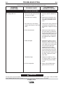
Only a brief spurt of a Pilot Arc
appears
Electrode Stuck in Torch head
a. Make sure the air pressure is
set correctly
b. Consumables may be improper-
ly assembled.
c. There may be oil in the air.
d. The Pro-Cut may be in expand-
ed metal mode.
e. The swirl ring may have holes
out of spec.
f. The Pro-Cut is not working prop-
erly.
a. The duty cycle may have been
exceeded
b. Make sure the Pro-Cut has the
larger solenoids (this applies to
codes 10097 and lower only)
c. Make sure the air pressure is
set properly.
a. Put the Pro-Cut in Purge and
adjust the air pressure to 55-65
psi while the air is flowing.
b. Make sure an electrode, swirl
ring, nozzle and shield cup are
assembled in the torch.
c. Check the filters in the regula-
tors for oil. Replace if neces-
sary and eliminate the source of
oil.
d. This is a normal condition which
occurs after several long pilot
arcs have been pulled in a row.
After a while, the Pro-Cut will
return to the standard pilot arc if
no pilot arcs are pulled for sev-
eral seconds.
e. Some swirl rings were shipped
with the swirl hole diameter too
large. If possible, use plug
gages to make sure the swirl
hole diameter is not larger than
.028”.
f. Refer to the troubleshooting
guide for the Pro-Cut 125.
a. Operate the Pro-Cut within the
duty cycle limits (125 Amps at
60%, 100 Amps at 100%.)
b. Install a S21237 solenoid kit.
c. Put the Pro-Cut in Purge and
adjust the air pressure to 55-65
psi while the air is flowing.

NOTES
PLASMA TORCH
La page est en cours de chargement...
La page est en cours de chargement...
La page est en cours de chargement...
La page est en cours de chargement...
La page est en cours de chargement...
-
 1
1
-
 2
2
-
 3
3
-
 4
4
-
 5
5
-
 6
6
-
 7
7
-
 8
8
-
 9
9
-
 10
10
-
 11
11
-
 12
12
-
 13
13
-
 14
14
-
 15
15
-
 16
16
-
 17
17
-
 18
18
-
 19
19
-
 20
20
-
 21
21
-
 22
22
-
 23
23
-
 24
24
-
 25
25


Lincoln Electric MAGNUM PCT125 Manuel utilisateur
- Catégorie
- Système de soudage
- Taper
- Manuel utilisateur
dans d''autres langues
Documents connexes
-
Lincoln Electric K2820-1 Manuel utilisateur
-
-
-
Lincoln Electric 10475 Manuel utilisateur
-
-
-
-
-
-
Autres documents
-
ESAB PT-20AMX and PT-21AMX Plasmarc Cutting Torches Manuel utilisateur
-
ESAB ESP-101 Manuel utilisateur
-
Maxim 23039SWSN Guide d'installation
-
-
-
-
-
ESAB PT-38 Plasmarc Cutting Torches Manuel utilisateur
-
Harris POWERTORCH PLASMA 20 Manuel utilisateur
-
Rain Bird 42SA Mode d'emploi