Miller KH339697 Le manuel du propriétaire
- Catégorie
- Système de soudage
- Taper
- Le manuel du propriétaire
Ce manuel convient également à

Miller
The
Power
ofBlue.
OM1587F
February
1997
En.
wlSenal
Number
KH339697
Processes
~
MIG
(GMAW)
Welding
Pulsed
MIG
(GMAW-P)
Flux
Cored
(FCAW)
Welding
(Gas-
and
Self-Shielded)
flp~miint
inn
1~~~
Wire
Feeder
(Use
with
CC/CV
Power
Sources)
!J-~
)-i
CE
OWNERS_MANUAL

Thank
you
and
congratulations
on
choosing
Miller.
Now
you
can
get
the
job
done
and
get
it
done
right.
We
know
you
dont
have
time
to
do
it
any
other
way.
Thats
why
when
Neils
Miller
first
started
building
arc
welders
in
1929,
he
made
sure
his
products
offered
long-lasting
value
and
superior
quality.
Like
you,
his
customers
couldnt
afford
anything
less.
Miller
products
had
to
be
more
than
the
best
they
could
be.
They
had
to
be
the
best
you
could
buy.
Today,
the
people
that
build
and
sell
Miller
products
continue
the
tradition.
Theyre
just
as
committed
to
providing
equipment
and
service
that
meets
the
high
standards
of
quality
and
value
established
in
1929.
This
Owners
Manual
is
designed
to
help
you
get
the
most
out
of
your
Miller
products.
Please
take
time
to
read
the
Safety
precautions.
They
will
help
you
protect
yourself
against
potential
hazards
on
the
worksite.
Weve
made
installation
and
operation
quick
and
easy.
With
Miller
you
can
count
on
years
of
reliable
service
with
proper
maintenance.
And
if
for
______________
some
reason
the
unit
needs
repair,
theres
a
Troubleshooting
section
that will
help
you
figure
out
what
the
problem
is.
The
parts
list
will
then
help
you
to
decide
which
exact
part
you
may
need
to
fix
the
problem.
Warranty
and
service
information
for
your
particular
model
are
also
provided.
Miller
Electric
manufactures
a
full
line
of
welders
and
welding
related
equipment.
For
information
on
other
quality
Miller
products,
contact
your
local
Miller
distributor
to
receive
the
latest
full
line
catalog
or
individual
catalog
sheets.
To
locate
your
nearest
distributor
call
1-800-4-A-Miller.
From
-]
to
You
.
iIf~{IIiIIIII
p
REGISTERED
QUALITY
SYSTEM
Miller
is
the
first
welding
equipment
manufacturer
in
the
U.S.A.
to
be
registered
to
the
ISO
9001
Quality
System
Standard.
~1~ll1ftE~ftflJ1!
Working
as
hard
as
you
do
every
power
source
from
Miller
Is
backed
by
the
most
hassle-free
warranty
in
the
business.
f//A
Miller
TheThwerofBki&

Call
1
-800-4-A-MIU.EB
for
your
local
Miller
distributor.
Your
distributor
gives
you
Service
You
always
get
the
fast,
reliable
response
you
need.
Most
replacement
parts
can
be
in
your
hands
in
24
hours.
Support
Need
fast
answers
to
the
tough
welding
questions?
Contact
your
distributor.
The
expertise
of
the
distributor
and
Miller
is
there
to
help
you,
every
step
of
the
way.
Description
Put
the
benefits
of
technology
to
work
on
the
production
line.
The
D-64M
represents
a
major
advancement
in
wire
feed
technology,
and
delivers
the
ultimate
in
versatility,
simplicity,
programmability
and
performance.
The
D-64M
feeder
includes
special
features
for
pulsed
MIG
(GMAW-P)
welding
that
requires
the
use
of
inverter-type
power
sources.
However
the
D-64M
retains
the
versatility
that
makes
it
i+~,.1
s,.
,.nn.,~nt,nn~I
ItAI(~
~
....~
using
a
vanety
of Miller
CV
or
CC/CV
machines.
For
pulsed
MIG
welding,
the
D-64M
features
built-in
memory
with
eight,
factory-set
synergic
pulse
programs.
Each
program
is
specific
for
a
wire
type,
wire
size
and
gas
mixture.
Any
of
these
programs
can
be
modified
for
the
specific
requirements
of
your
welding
application.
This
dual
wire
model
operates
one
gun
at
a
time,
and
provides
efficiency
in
applications
that
alternately
require
wires
of
two
different
sizes
or
types.
Its
also
ideal
in
situations
where
a
standby
gun
is
needed.
This
dual-wire
model
can
be
programmed
to
run
the
identical
process
on
both
sides,
or
to
have
one
side
run
conventional
MIG
while
the
other
is
set
for
pulsed
MIG
welding.
Table
of
Contents
Section
1.
Safety
Precautions
1.
Consignes
de
SØcuritØ
pour
le
Soudage
a
Larc
2.
Definitions
3.
Introduction
4.
Installation
5.
Operation
6.
Setting
Sequence
Parameters
7.
Setting
Dual
Schedule
Parameters
8.
Using
the
Optional
Data
Card
2-line
by
16-character
backlit
LCD
Single
push-button
parameter
select
control
Single
knob
parameter
adjustment
Trigger
hold
control
for
making
extended
welds
without
holding
gun
tngger
Wire
jog
control
feeds
wire
without
energizing
the
contactor
Gas
purge
control
purges
line
without
energizing
feeder
Side
Panel
Features
4-line
by
20-character
backiit
LCD
for
parameter
and
mode
displays
Push-button
programming
controls
for
process,
sequence,
dual
schedule,
and
data
card
modes
Parameter
select
push
button
Parameter
increase/decrease
push
buttons
Processes
MIG
(GMAW)
Welding
Pulsed
MIG
(GMAW-P)
4
Flux
Cored
(FCAW)
Welding
(Gas-
and
Self-Shielded)
Miller
offers
a
Technical
Manual
7
which
provides
more
detailed
service
and
parts
information
for
9
your
unit.
To
obtain
a
Technical
Manual,
contact
your
local
9
distributor.
Your
distributor
can
also
supply
you
with
Welding
Process
15
ManualssuchasSMAW,
GTAW,
GMAW,
and
GMAW-P.
18
19
21
Options
and
Accessories
r\
Front
Panel
Features
Page
:
1
9.
System
Setup
23
10.
Standard
Pulse
Welding
Programs
24
11.
Teach
Points
26
12.
Maintenance
and
Troubleshooting
30
13.
Electrical
Diagram
34
14.
Parts
List
36
Warranty

Declaration
of
Conformity
for
European
Community
(CE)
Products
Note
~
This
information
is
provided
for
units
with
CE
certification
(see
rating
label
on
unit).
.
Manufacturers
Name:
Manufacturers
Address:
Declares
that
the
product
Miller
Electric
Mfg.
Co.
1635 W.
Spencer
Street
Appleton,
WI
54914
USA
D-64M
conforms
to
the
following
Directives
and
Standards:
Directives
Low
Voltage
Directive:
73/23/EEC
Electromagnetic
Compatibility
(EMC)
Directive:
89/336/EEC
Machinery
Directives:
89/392/EEC,
91/368/EEC,
93/C
133/04,
93/68/EEC
Standards
Arc
Welding
Equipment
Part
I:
Welding
Power
Sources:
lEG
974-1
(April
1995
Draft
Revision)
Arc
Welding
Equipment:
Wirefeed
Systems:
IEC
974-4
(May
1995
Draft
Revision)
Degrees
of
Protection
Provided
By
Enclosures
(IP
Code):
IEC
529:1989
Insulation
Coordination
For
Equipment
With
Low-Voltage
Systems:
Part
I:
Principles,
Requirements
and
Tests:
lEG
664-1:
1992
Electromagnetic
Compatibility,
(EMC):
EN
50199
European
Contact
Telephone:
Fax:
Mr.
Luigi
Vacchini,
Managing
Director
MILLER
Europe
S.P.A.
Via
Privata
Iseo
20098
San
Giuliano
Milanese,
Italy
39(02)98290-1
39(02)98281-552
dec_con
11/96

1.
Safety
Precautions
Read
Before
Using
1.1
SymbOl
Usage
a
Means
Warning!
Watch
Out!
There
are
possible
hazards
with
this
procedure!
The
possible
hazards
are
shown
in
the
adjoining
symbols.
A
Marks
a
special
safety
message.
IE?
Means
~Note;
not
safety
related.
t2
Arc
Welding
Hazards
A
The
symbols
shown
below
are
used
throughout
this
manual
to
call
attention
to
and
identify
possible
hazards.
When
you
see
the
symbol,
watch
out,
and
follow
the
related
instructions
to
avoid
the
hazard.
The
safety
information
given
below
is
only
a
summary
of
the
more
complete
safety
information
found
in
the
Safety
Standards
listed
in
Section
1.3.
Read
and
follow
all
Safety
Standards.
A
Only
qualified
persons
should
install,
operate,
maintain,
and
repair
this
unit.
A
During
operation,
keep
everybody,
especially
children,
away.
ELECTRIC
SHOCK
can
kill
Touching
live
electrical
parts
can
cause
fatal
shocks
or
severe
bums.
The
electrode
and
work
circuit
is
electrically
live
whenever
the
output
is
on.
The
input
power
circuit
and
machine
internal
circuits
are
also
live
when
power
is
on.
In
semiautomatic
or
automatic
wire
welding,
the
wire,
wire
reel,
drive
roll
housing,
and
all
metal
parts
touching
the
welding
wire
are
electrically
live.
Incorrectly
installed
or
improperly
grounded
equipment
is
a
hazard.
Do
not
touch
live
electrical
parts.
Wear
dry,
hole-free
insulating
gloves
and
body
protection.
Insulate
yourself
from
work
and
ground
using
dry
insulating
mats
or
covers
big
enough
to
prevent
any
physical
contact
with
the
work
or
ground.
Disconnect
input
power
or
stop
engine
before
installing
or
servicing
this
equipment.
Lockout/tagout
input
power
according
to
OSHA
29
CFR
191
0.147
(sec
Safety
Standards).
Properly
install
and
ground
this
equipment
according
to
its
Owners
Manual
and
national,
state,
and
local
codes.
Always
verify
the
supply
ground
check
and
be
sure
that
input
power
cord
ground
wire
is
properly
connected
to
ground
terminal
in
disconnect
box
or
that
cord
plug
is
connected
to
a
properly
grounded
receptacle
outlet.
When
making
input
connections,
attach
proper
grounding
conductor
first
double-check
connections.
Frequently
inspect
input
power
cord
for
damage
or
bare
wiring
replace
cord
immediately
if
damaged
bare
wiring
can
kill.
Turn
off
all
equipment
when
not
in
use.
Do
not
use
worn,
damaged,
undersized,
or
poorly
spliced
cables.
Do
not
drape
cables
over
your
body.
-
If
earth
grounding
of
the
workpiece
is
required,
ground
it
directly
with
a
separate
cable
-
do
not
use
work
clamp
or
work
cable.
Do
not
touch
electrode
if
you
are
in
contact
with
the
work,
ground,
or
another
electrode
from
a
different
machine.
Use
only
well-maintained
equipment.
Repair
or
replace
damaged
parts
at
once.
Maintain
unit
according
to
manual.
Wear
a
safety
harness
if
working
above
floor
level.
OM-1587F
.2197,
safety_som
11/96
This
group
of
symbols
means
Warning!
Watch
Out!
possible
ELECTRIC
SHOCK,
MOVING
PARTS,
and
HOT
PARTS
hazards.
Consult
symbols
and
related
instructions
below
for
necessary
actions
to
avoid
the
hazards.
Keep
au
paneis
and
covers
Seuureiy
ifi
place.
Clamp
work
cable
with
good
metal-to-metal
contact
to
workpiece
or
worktable
as
near
the
weld
as
practical.
SIGNIFICANT
DC
VOLTAGE
exists
after
removal
of
input
power
on
inverters.
Turn
Off
inverter,
disconnect
input
power,
and
discharge
input
capacitors
according
to
instructions
in
Maintenance
Section
before
touching
any
parts.
ARC
RAYS
can
burn
eyes
and
skin
Arc
rays
from
the
welding
process
produce
intense
~\..
~
visible
and
invisible
(ultraviolet
and
infrared)
rays
that
can
bum
eyes
and
skin.
Noise
from
some
processes
can
damage
hearing.
Chipping,
grinding,
and
welds
cooling
throw
off
pieces
of
metal
or
slag.
Wear
a
welding
helmet
fitted
with
a
proper
shade
offilterto
protect
your
face
and
eyes
when
welding
or
watching
(see
ANSI
Z49.1
and
Z87.1
listed
in
Safety
Standards).
Wear
approved
safety
glasses
with
side
shields.
Use
protective
screens
or
bamers
to
protect
others
from
flash
and
glare;
warn
others
not
to
watch
the
arc.
Wear
protective
clothing
made
from
durable,
flame-resistant
rnaterial
(wool
and
leather)
and
foot
protection.
FUMESANDGASEScanbe
hazardous
L......
~
~
Welding
produces
fumes
and
gases.
Breathing
these
fumes
and
gases
can
be
hazardous
to
your
health.
Keep
your
head
out
of
the
fumes.
Do
not
breathe
the
fumes.
If
inside,
ventilate
the
area
and/or
use
exhaust
at
the
arc
to
remove
welding
fumes
and
gases.
If
ventilation
is
poor,
use
an
approved
air-supplied
respirator.
Read
the
Material
Safety
Data
Sheets
(MSDSs)
and
the
manufacturers
instructions
for
metals,
consumables,
coatings,
cleaners,
and
degreasers.
Work
in
a
confined
space
only
if
it
is
well
ventilated,
or
while
wearing
an
air-supplied
respirator.
Always
have
a
trained
watch-
person
nearby.
Welding
fumes
and
gases
can
displace
air
and
lower
the
oxygen
level
causing
injury
or
death.
Be
sure
the
breathing
air
is
safe.
Do
not
weld
in
locations
near
degreasing,
cleaning,
or
spraying
operations.
The
heat
and
rays
of
the
arc
can
react
with
vapors
to
form
highly
toxic
and
irritating
gases.
Do
not
weld
on
coated
metals,
such
as
galvanized,
lead,
or
cadmium
plated
steel,
unless
the
coating
is
removed
from
the
weld
area,
the
area
is
well
ventilated,
and
if
necessary,
while
wearing
an
air-supplied
respirator.
The
coatings
and
any
metals
containing
these
elements
can
give
off
toxic
fumes
if
welded.
OM-1
587
1

WELDING
can
causefireorexplosion.
Welding
on
closed
containers,
such
as
tanks,
drums,
or
pipes,
can
cause
them
to
blow
up.
Sparks
can
fly
off
from
the
welding
arc.
The
flying
sparks,
hot
workpiece,
and
hot
equipment
can
cause
fires
and
burns.
Accidental
contact
of
electrode
to
metal
objects
can
cause
sparks,
explosion,
overheating,
or
fire.
Check
and
be
sure
the
area
is
safe
before
doing
any
welding.
Protect
yourself
and
others
from
flying
sparks
and
hot
metal.
Do
not
weld
where
flying
sparks
can
strike
flammable
material.
Remove
all
flammables
within
35
ft
(10.7
m)
of
the
welding
arc.
If
this
is
not
possible,
tightly
cover
them
with
approved
covers.
Be
alert
that
welding
sparks
and
hot
materials
from
welding
can
easily
go
through
small
cracks
and
openings
to
adjacent
areas.
Watch
for
fire,
and
keep
a
fire
extinguisher
nearby.
Be
aware
that
welding
on
a
ceiling,
floor,
bulkhead,
or
partition
can
cause
fire
on
the
hidden
side.
Do
not
weld
on
closed
containers
such
as
tanks,
drums,
or
pipes,
unless
they
are
property
prepared
according
to
AWS
F4.i
(see
Safety
Standards).
Connect
work
cable
to
the
work
as
close
to
the
welding
area
as
practical
to
prevent
welding
current
from
traveling
long,
possibly
unknown
paths
and
causing
electric
shock
and
fire
hazards.
Do
not
use
welder
to
thaw
frozen
pipes.
Remove
stick
electrode
from
holder
or
cut
oft
welding
wire
at
contact
tip
when
not
in
use.
Wear
oil-free
protective
garments
such
as
leather
gloves,
heavy
shirt,
cuffless
trousers,
high
shoes,
and
a
cap.
Remove
any
combustibles,
such
as
a
butane
lighter
or
matches,
from
your
person
before
doing
any
welding.
H.F.
RADIATiON
cancaUse
Interference.
High-frequency
(H.F.)
can
interfere
with
radio
navigation,
safety
services,
computers,
and
communications
equipment.
Have
only
qualified
persons
familiar
with
electronic
equipment
perform
this
installation.
The
user
is
responsible
for
having
a
qualified
electrician
promptly
correct
any
interference
problem
resulting
from
the
installation.
If
notified
by
the
FCC
about
interference,
stop
using
the
equipment
at
once.
Have
the
installation
regularly
checked
and
maintained.
Keep
high-frequency
source
doors
and
panels
tightly
shut,
keep
spark
gaps
at
correct
setting,
and
use
grounding
and
shielding
to
minimize
the
possibility
of
interference.
FIRE
OR
EXPLOSION
hazard.
Do
not
install
or
place
unit
on,
over,
or
near
combustible
surfaces.
Do
not
locate
unit
on,
over,
or
near
combustible
surfaces.
Do
not
install
unit
near
flammables.
Do
not
overload
building wiring
be
sure
power
supply
system
is
properly
sized,
rated,
and
protected
to
handle
this
unit.
OVERUSE
can
cause
OVERHEATING
Allow
cooling
period,
follow
rated
duty
cycle.
Reduce
current
or
reduce
duty
cycle
before
starting
to
weld
again.
Do
not
block
or
filter
airflow
to
unit.
MAGNETIC
FiELDS
can
affect
pacemakers.
Pacemaker
wearers
keep
away.
Wearers
should
consult
their
doctor
before
going
near
arc
welding,
gouging,
or
spot
welding
operations.
HOT
PARTS
can
cause
severe
burns.
Do
not
touch
hot
parts
bare
handed.
Allow
cooling
period
before
working
on
gun
or
torch.
MOVING
PARTS
can
cause
injury.
Keep
away
from
moving
parts
such
as
fans.
Keep
all
doors,
panels,
covers,
and
guards
closed
and
securely
in
place.
WELDING
WIRE
can
cause
injury
Do
not
press
gun
trigger
until
instructed
to
do
so.
Do
not
point
gun
toward
any
part
of
the
body,
other
people,
or
any
metal
when
threading
welding
wire.
CYLINDERS
can
explode
If
damaged
Shielding
gas
cylinders
contain
gas
under
high
pressure.
If
damaged,
a
cylinder
can
explode.
Since
gas
cylinders
are
normally
part
of
the
welding
process,
be
sure
to
treat
them
carefully.
Protect
compressed
gas
cylinders
from
excessive
heat,
mechanical
shocks,
slag,
open
flames,
sparks,
and
arcs.
Install
cylinders
in
an
upright
position
by
securing
to
a
stationary
support
or
cylinder
rack
to
prevent
falling
or
tipping.
Keep
cylinders
away
from
any
welding
or
other
electrical
circuits.
Never
drape
a
welding
torch
over
a
gas
cylinder.
Never
allow
a
welding
electrode
to
touch
any
cylinder.
Never
weld
on
a
pressurized
cylinder
explosion
will
result.
Use
only
correct
shielding
gas
cylinders,
regulators,
hoses,
and
fittings
designed
for
the
specific
application;
maintain
them
and
associated
parts
in
good
condition.
Tum
face
away
from
valve
outlet
when
opening
cylinder
valve.
Keep
protective
cap
in
place
over
valve
except
when
cylinder
is
in
use
or
connected
for
use.
Read
and
follow
instructions
on
compressed
gas
cylinders,
associated
equipment,
and
CGA
publication
P-i
listed
in
Safety
Standards.
.
FLYING
METAL
can
injure
eyes
Chipping
and
grinding
cause
flying
metal.
As
welds
cool,
they
can
throw
off
pieces
of
metal
or
slag.
Wear
a
face
shield
to
protect
eyes
and
skin.
2
OM-1
587

NOISE
can
damage
hearing
Noise
from
some
processes
or
equipment
can
damage
hearing.
Wear
approved
ear
protection
if
noise
level
is
high.
STATIC
(ESD)
can
damage
PC
boards
Put
on
grounded
wrist
strap
BEFORE
handling
boards
or
parts.
Use
proper
static-proof
bags
and
boxes
to
store,
move,
or
ship
PC
boards.
MOVING
PARTS
can
cause
injury
Keep
away
from
moving
parts.
Keep
away
from
pinch
points
such
as
drive
rolls.
1
3
Principal
Safety
Standards
Safely
in
Welding
and
Cutting,
ANSI
Standard
Z49.1,
from
American
Welding
Society,
550
N.W.
LeJeune
Rd,
Miami
FL
33126
Safety
and
Health
Standards,
OSHA
29
CFR
1910,
from
Superinten
dent
of
Documents,
U.S.
Government
Printing
Office,
Washington,
D.C.
20402.
Recommended
Safe
Practices
for
the
Preparation
for
Welding
and
Cutting
of
Containers
That
Have
Held
Hazardous
Substances,
American
Welding
Society
Standard
AWS
F4.1,
from
American
Welding
Society,
550
N.W.
LeJeune
Rd,
Miami,
FL
33126
National
Electrical
Code,
NFPA
Standard
70,
from
National
Fire
Protection
Association,
Batterymarch
Park,
Quincy,
MA
02269.
FLWNG
METAL
or
DIRT
can
injure
eyes.
Wear
safety
glasses
with
side
shields
or
face
shield.
FALLING
UNIT
can
cauŁe
injury.
Use
lifting
eye
to
lift
unit
only,
NOT
running
gear,
gas
cylinders,
or
any
other
accessories.
Use
equipment
of
adequate
capacity
to
lift
unit.
If
using
lift
forks
to
move
unit,
be
sure
forks
are
long
enough
to
extend
beyond
opposite
side
of
unit.
BUILDUP
OF
GAS
can
injUreor.
kill.
Shutoff
shielding
gas
supply
when
not
in
use.
Safe
Handling
of
Compressed
Gases
in
Cylinders,
CGA
Pamphlet
P-i,
from
Compressed
Gas
Association,
1235
Jefferson
Davis
Highway,
Suite
501,
Arlington,
VA
22202.
Code
for
Safety
in
Welding
and
Cuffing,
CSA
Standard
Wi
17.2,
from
Canadian
Standards
Association,
Standards
Sales,
178
Rexdale
Boulevard,
Rexdale,
Ontario,
Canada
M9W
1
R3.
Safe
Practices
For
Occupation
And
Educational
Eye
And
Face
Protection,
ANSI
Standard
Z87.1
,
from
American
National
Standards
Institute,
1430
Broadway,
New
York,
NY
10018.
Cutting
And
Welding
Processes,
NFPA
Standard
51
B,
from
National
Fire
Protection
Association,
Batterymarch
Park,
Quincy,
MA
02269.
1.4.
:EMF
Information
Considerations
About
Welding
And
The
Effects
Of
Low
Frequency
Electric
And
Magnetic
Fields
The
following
is
a
quotation
from
the
General
Conclusions
Section
of
the
U.S.
Congress,
Office
of
Technology
Assessment,
Biological
Effects
of
Power
Frequency
Electric
&
Magnetic
Fields
Background
Paper~
OTA-BP-E-53
(Washington,
DC:
U.S.
Government
Printing
Office,
May
1989):..
.
there
is
now
a
very
large
volume
of
scientific
findings
based
on
experiments
at
the
cellular
level
and
from
studies
with
animals
and
people
which
clearly
establish
that
low
frequency
magnetic
fields
can
interact
with,
and
produce
changes
in,
biological
systems.
While
most
of
this
work
is
of
very
high
quality,
the
results
are
complex.
Current
scientific
understanding
does
not
yet
allow
us
to
in
terpret
the
evidence
in
a
single
coherent
framework.
Even
more
frustrating,
it
does
not
yet
allow
us
to
draw
definite
conclusions
about
questions
of
possible
risk
or
to
offer
clear
science-based
advice
on
strategies
to
minimize
or
avoid
potential
risks.
To
reduce
magnetic
fields
in
the
workplace,
use
the
following
procedures:
1.
Keep
cables
close
together
by
twisting
or
taping
them.
2.
Arrange
cables
to
one
side
and
away
from
the
operator.
3.
Do
not
coil
or
drape
cables
around
the
body.
4.
Keep
welding
power
source
and
cables
as
far
away
from
opera
tor
as
practical.
5.
Connect
work
clamp
to
workpiece
as
dose
to
the
weld
as
possible.
AbOUt
Pacemakers:
The
above
procedures
are
also
recommended
for
pacemaker
wearers.
Consult
your
doctor
for
complete
information.
OM-1
587
3

1.
Consignes
do
SØcuritØ
POUP
10
Soudage
a
larc
UN
CHOC
ELECTRIQUE
peut
tuer.
Un
simple
contact
avec
des
piŁces
electriques
peut
pro
voquer
une
electrocution
ou
des
blessures
graves.
LØ
lectrode
et
le
circuit
de
soudage
sont
sous
tension
des
que
lappareil
est
sur
ON.
Le
circuit
dentrØe
et
es
cir
cuits
intemes
de
apparel!
sont
Øgalement
sous
tension
a
ce
moment-l.
En
soudage
semi-automatique
ou
automatique,
le
fil,
le
dØvidoir,
le
logement
des
galets
dentralnement
et
lea
piŁces
mØtalliques
en
contact
avec
le
fil
de
soudage
sont
sous
tension.
Des
matØnels
ma!
installØs
ou
ma! mis
ala
terre
prØsentent
un
danger.
1.
Ne
jamais
toucher
les
piŁces
electriques
sous
tension.
2.
Porter
des
gants
et
des
vØtements
de
protection
secs
ne
compor
tant
pas
de
trous.
3.
Sisoler
de
Ia
piŁce
et
de
Ia
terre
au
moyen
de
tapis
ou
dautres
moyens
isolants
suffisamment
grands
pour
empØcher
le
contact
physique
Øventuel
avec
Ia
piŁce
ou
Ia
terre.
4.
Couper
lalimentation
ou
arrŒter
le
moteur
avant
de
proceder
a
linstallation,
a
a
reparation
ou
a
lentretien
de
lappareil.
DØver
rouiller
lalimentation
selon
Ia
norme
OSHA
29
CFR
191
0.147
(voir
normes
de
sØcurite).
5.
Installer
et
mettre
a
Ia
terre
correctement
cet
appareil
conformØ
ment
a
son
manuel
dutilisation
et
au
codes
nationaux,
provin
ciaux
et
municipaux.
6.
ToujoursvØnfier
laterre
du
cordon
dalimentation
Verifier
et
sas
surer
aue
le
fil
de
terre
du
cordon
dalimentation
est
bien
raccordØ
1
3.Ne
pas
toucher
lØlectrode
quand
on
est
en
contact
avec
Ia
piŁce,
Ia
terre
ou
une
electrode
provenant
dune
autre
machine.
14.
Nutiliser
quun
materiel
en
bon
Øtat.
Reparer
ou
remplacersur-le
champ
!es
piŁces
endommagees.
Entretenir
lappareil
conformØ
ment
a
ce
manuel.
15.
Porter
un
hamais
de
sØcuntØ
quand
on
travaille
en
hauteur.
16.Maintenir
solidement
en
place
tousles
panneaux
et
capots.
17.
Fixer
le
cable
de
retour
de
facon
a
obtenir
un
bon
contact
metal
metal
avec
Ia
piŁce
a
souder
ou
Ia
table
de
travail,
Ie
plus
prØs
possible
de
Ia
soudure.
BRUIT
LE
RAYONNEMENT
DE
LARC
peut
brler
les
yeux
et
Ia
peau.
Le
BRUIT
peut
endommager
louIe;
les
PROJECTIONS
DE
LAITIER
OU
LES
ETINCELLES
peuvent
blesser
les
yeux.
Larc
de
soudage
produit
des
rayons
visibles
et
invi
sibles
intenses
(ultraviolets
et
intrarouges)
qui
peuv
ent
brUler
les
yeux
et
Ia
peau.
Le
bruit
produit
par
cer
tains
procØdes
peut
endommager
louie.
Des
projec
tions
de
metal
ou
de
laitier
sont
produites
par
le
piquage,
le
meulage
ou
le
refroidissement
des
sou
dures.
1.
Utiliser
des
bouche-oreilles
ou
des
serre-tŒte
antibruit
approuvØs
si
!e
niveau
de
bruit
est
ØlevØ.
___________-
RAYONNEMENT
DE
LARC
2.
Porter
un
masque
a
serre-tŒte
muni
dun
verre
filtrantde
nuance
appropnØe
pour
protØger
le
visage
et
lea
yeux
quand
on
soude
ou
observe
Ia
travail
de
soudage
(voir
les
normes
ANSI
Z49.1
et
Z87.1
donnØes
sous
Ia
rubrmque
Principales
normes
de
sØcu
rite).
3.
Porter
des
lunettes
de
sØcuritØ
approuvØes
avec
Øcrans
late
raux.
4.
Utiliser
des
paravents
ou
des
bamŁres
de
protection
pour
protØger
les
personnes
a
proximitØ
contre
les
coups
darc
et
IØblouissement;
avertir
lea
autres
personnes
de
ne
pas
regarder
Iarc.
5.
Porter
des
vŒtements
de
protection
en
tissu
ignituge
durable
(lame
et
cuir)
et
des
chaussures
de
sØcuritØ.
11
Signification
des
oM:1
587FIcf
r
2/97
symboles
safety_som_cfr
2/97
%\~
Signifie
Mise
en
garde!
&~
presenter
des
dangers!
les
divers
sym
boles.
Attention!
Ce
mode
opØratoire
peut
A
Indique
un
message
de
sØcuritØ
special.
Les
dangers
possibles
sont
indiques
par
~
Signifie
NOTA;
pas
lie
a
Ia
sØcutitØ
Ce
groupe
de
symboles
signifie
Mise
en
garde!
Attention!,
risque
de
CF-lOGS
ELECTRIQUES,
dangers
presentes
par
les
PIECES
MOBILES
et
les
PIECES
CHAUDES.
Voir
les
symboles
et
es
~1~~::r:ssoc~s
ci-apres
pour
prendre
les
mesures
nØcessaires
atm
de
se
premunir
contre
,-.
r
1
2
Dangers
du
soudage
a
Iarc
A~
MISE
EN
GARDE
Les
symboles
donnØs
ci-aprŁs
sont
utilisØs
dans
tout
le
manuel
pour
attirer
lattention
sur
les
dangers
possibles
et
pour
indiquer
le
type
de
danger
dont
ii
sagit.
Quand
on
volt
le
symbole,
prendre
garde
et
suivre
Ies
directives
correspondantes
pour
Øviter
le
danger.
Les
consignes
de
sØcuritØ
donnØes
ci-aprŁs
ne
font
que
rØsumer
Iinformation
contenue
dans
les
normes
de
sØcuritØ
ØnumØrØes
a
Ia
section
1-4.
Lire
et
respecter
toutes
ces
normes
de
sØcuritØ.
Linstallation,
Iutilisation,
lentretien
et
les
reparations
ne
doivent
Œtre
confiØs
qu
des
personnes
qualifiØes.
Aucune
personne,
et
particuliŁrement
es
enfants,
ne
doit
se
trouver
a
proximitØ
du
poste
de
soudage.
a
Ia
borne
de
terre
du
sectionneur
ou
que
a
fiche
du
cordon
est
raccordØe
a
une
pnse
correctement
mise
a
Ia
terre.
7.
En
effectuant
les
raccordements
dentrØe
fixer
dabord
le
conduc
teur
de
mise
ala
terre
appropne
et
contre-vØnfier
les
connexions.
8.
Verifier
frequemment
le
cordon
dalimentation
pour
voir
si!
nest
pas
endommage
ou
dØnudØ
remplacer
le
cordon
immediate
ment
si!
est
endommage
un
cable
dØnudØ
peut
provoquer
une
electrocution.
9.
Mettre
lappareil
hors
tension
quand
on
ne
lutilise
pas.
10.
Ne
pas
utiliser
des
cables
uses,
endommages,
de
grosseur
insuf
fisante
ou
ma!
ØpissØs.
11.
Ne
pas
enrouler
les
cables
autour
du
corps.
12.Si
Ia
piŁce
soudØe
doit
Œtre
mise
a
a
terre,
le
faire
directement
avec
un
cable
distinctne
pas
utiliser
le
connecteurde
piŁce
ou
le
cable
de
retour.
.
4
OM-1
587

~
LES
VAPEURS
ET
LES
FUMEES
peuvent
Œtre
dangereuses
pour
Ia
sante.
~
I
Le
soudage
produit
des
vapeurs
et
des
fumØes
quil
est
=9~
~
dangereux
de
respirer.
1.
Garder
Ia
tŒte
a
lextØrieur
des
vapeurs
et
des
fumees
et
ne
pas
les
respirer.
2.
A
lintØneur,
ventiler
le
poste
de
travail
ou
utiliser
un
dispositif
place
au
niveau
de
larc
pour
Øvacuer
les
vapeurs
et
fumØes
de
soudage.
3.
Si
Ia
ventilation
est
mauvaise,
utiliser
un
appareil
respiratoire
a
adduction
dair
pur
approuve.
4.
Consulter
les
fiches
signaletiques
et
les
consignes
du
fabncant
relatives
au
mØtaux,
produits
dapport,
revŒtements,
nettoyants
et
LES
BOUTEILLES
peuvent
exploser
Si
elles
sont
endommagees.
Lea
bouteiiies
cOfli~Fiaflt
des
ga~
de
protection
SOflt
a
haute
prepsion.
Une
bouteille
endommagØe
peut
exploser.
Etant
donnØ
que
es
bouteilles
de
gaz
font
normalement
partie
du
matØnel
de
soudage,
les
traiter
avec
le
plus
grand
soin.
1.
Proteger
les
bouteilles
de
gaz
comprime
contre
Ia
chaleur
intense,
les
chocs,
le
laitier,
les
flammes
nues,
les
Øtincelles
et
larc.
2.
Placer
les
bouteilles
ala
verticale
en
les
fixant
a
un
support
fixe
ou
a
un
chariot
pour
Øviter
quelles
ne
tombent
ou
ne
basculent.
3.
Tenir
les
bouteilles
a
lØcart
du
poste
de
soudage
ou
dautres
circuits
Ølectriques.
Ne
pas
souder
sur
des
recipients
fermØs
comme
des
reservoirs,
des
tOts
ou
des
tuyaux:
Is
peuvent
exploser.
Larc
de
soudage
peut
produire
des
Øtincelles.
Des
Øtincelles,
une
piŁce
chaude
et
un
matØnel
chaud
peuvent
provoquer
des
incendies
et
des
blessures.
Le
contact
accidentel
de
lØlectrode
sur
des
objets
mØtalliques
peut
produire
des
Øtincelles,
lexplosion,
Ia
surchauffe
ou
un
incendie.
Sassurer
que
le
lieu
ne
prØsente
pas
de
danger
avant
deffectuer
le
soudage.
1.
Se
protØger
et
proteger
lee
personnes
a
proximitØ
des
Øtincelles
et
du
metal
chaud.
2.
Ne
pas
souder
dans
un
endroit
oO
les
Øtincelles
peuvent
atteindre
des
matØnaux
inflammables.
3.
Enlevertoutes
les
matiŁres
inflammables
dans
un
rayon
de
moms
de
10
m
de
larc.
Si
cola
nest
pas
possible,
bien
les
recouvnr
en
utilisant
des
bches
approuvØes.
4.
Prendre
garde
que
les
Øtincelles
et
les
projections
ne
pØnØtrent
dane
des
zones
adjacentes
en
sinfiltrant
dans
des
petites
UN
INCENDIE
OU
UNE
EXPLOSION
peut
Œtre
cause
par
un
appareil
place
au
contact,
au-dessus
ou
a
ctØ
de
surfa
ces
combustibles.
1.
Ne
pas
placer
lappareil
au
contact,
au-dessus,
ou
a
ctØ
dune
surface
combustible.
2.
Ne
pas
installer
lappareil
a
ctØ
dun
objet
ou
dun
produit
inflammable.
EN
TOMBANT,
LE
MATERIEL
peut
sen
dommager
ou
causer
des
blessures
graves.
1.
Nutiliser
Ianneau
de
levage
que
pour
soulever
lappareil;
NE
PAS
lutiliser
pour
soulever
lee
cha
riots,
lee
bouteilles
de
gaz
ou
autres
accessoires.
2.
Pour
soulever
Ia
source
de
courant,
uliliser
des
appareils
de
puissance
suffisante.
3.
Si
Ion
ulilise
un
ØtØvateur
a
fourche
pour
dØplacer
lappareil,
sassurerque
Ia
fourche
est
suffisamment
longue
et
dØpasse
de
lautre
ctØ
de
Iappareil.
5.
Ne
travaillerdans
un
espace
confine
que
slIest
bien
ventilØ,
ou
en
portant
un
appareil
respiratoire
a
adduction
dair
pur.
Demander
a
un
observateur
ayant
reu
Ia
bonne
formation
de
toujours
se
tenir
a
proximitØ.
Les
vapeurs
etfumØes
de
soudage
peuvent
dØplacer
lair
et
abaisser
le
niveau
doxygene
et
causer
des
blessures
graves
voire
mortelles.
Sassurer
que
lair
est
propre
a
Ia
respiration.
6.
Ne
pas
souder
a
proximitØ
dopØrations
de
degraissage,
de
nettoyage
ou
de
pulvØrisation.
La
chaleur
et
es
rayons
de
arc
peuvent
rØagir
avec
fes
vapeurs
pour
former
des
gaz
hautement
toxiques
et
irritants.
7.
Ne
pas
souder
sur
des
mØtaux
revŒtus
comme
lacier
galvanisØ,
au
p10mb
ou
cadmiØ
a
moms
que
Ia
piŁce
nait
ØtØ
entierement
dØcapee,
que
le
poste
de
travail
soil
bien
ventilØ.
SiI
y
a
lieu,
porter
un
appareil
respiratoire
a
adduction
dair
pur.
Les
revØtements
et
lee
mØtaux
qui
contiennent
de
tels
ØlØments
peuvent
degager
des
vapeurs
toxiques
lors
du
soudage.
4.
Ne
jamais
poser
un
chalumeau
soudeur
sur
une
bouteille
de
gaz.
5.
Ne
jamais
laisser
une
electrode
de
soudage
toucher
une
bouteille.
6.
Nejamaic
coudersurune
boutei!!e
sous
pression
eI!e
explocerait
7.
Nutiliser
que
des
bouteilles
de
gaz
de
protection,
des
dØtendeurs,
des
tuyaux
souples
et
des
raccords
appropnØs
conus
pour
lapplication
particuliŁre;
conserver
ces
matØriels
et
leurs
piŁces
en
bon
Øtat.
8.
Eloigner
le
visage
de
Ia
sortie
du
robinet
de
Ia
bouteille
quand
on
louvre.
9.
Replacer
le
chapeau
sur
Ia
bouteille
aprŁs
utilisation.
10.Lire
et
suivre
les
consignes
relatives
aux
bouteilles
de
gaz
compnme,
au
matØnel
connexe
ainsi
que
Ia
publication
P-i
de
Ia
CGA
donnØe
sous
Ia
rubrique
Principales
norrnes
de
sØcuritØ.
6.
Se
rappeler
que
Si
Ion
soude
sur
un
plafond,
un
plancher,
une
cloison
ou
autre,
le
feu
peut
prendre
de
Iautre
ctØ.
7.
Ne
pas
souder
cur
des
recipients
fermØs
comme
des
reservoirs,
des
tOts
ou
des
tuyaux
a
moms
quiIs
ne
soient
prØparØs
de
faon
appropriee
conformØment
a
Ia
norme
F4.1
de
IAWS
(voir
Ia
rubrique
Prlncipales
normes
de
sØcuntØ).
8.
Raccorder
le
cable
de
retour
ala
piŁce,
le
plus
prØs
possible
de
Ia
zone
de
soudage,
pour
empŒcher
que
le
courant
de
soudage
ne
suive
une
trajectoire
longue
etØventuellement
inconnue
etquiI
ne
provoque
des
risques
dØlectrocution
et
dincendie.
9.
Ne
pas
utiliser
le
chalumeau
soudeur
pour
degeler
des
tuyaux.
10.
Enlever
IØlectrode
enrobØe
du
porte-electrode
ou
couper
le
fil
de
soudage
au
ras
du
bec
contact
quand
on
ne
Iutilise
pas.
ii.
Porter
des
vŒtements
de
protection
non
huileux
comme
des
gants
en
cuir,
une
chemise
Øpaisse,
des
pantalons
sans
revers,
des
chaussures
montantes
et
un
casque.
12.Ne
pas
porter
des
matiŁres
combustibles
cur
soi
comme
un
bnnupt
~
naz
ou
des
allumettes
puand
on
soude
LES
PI¨CES
CHAUDES
peuvent
provo
quer
des
brlures
graves.
1.
Ne
pas
toucher
les
piŁces
chaudes
les
mains
nues.
2.
Laisser
une
periode
de
ref
roidissement
avant
de
toucher
le
pistolet
ou
Ia
torche.
LES
PI¨CES
MOBILES
peuvent
causer
des
blessures.
1.
Se
tenir
a
IØcart
des
piŁces
en
mouvement
corn-
me
les
ventilateurs.
2.
Sassurer
que
tous
lee
capote,
panneaux,
portes
et
protecteurs
sont
bien
fermØs
et
fermement
maintenus.
LES
ECLATS
DE
METAL
ou
LES
SALE
TES
peuvent
provoquer
des
lesions
aux
yeux.
1.
Porter
des
lunettes
de
sØcuntØ
avec
Øcrans
late
raux
ou
Øcran
facial.
LE
SOUDAGE
peut
causer
un
incendie
ou
5.
Prendre
garde
aux
incendies
et
toujours
avoir
un
extincteur
a
une
explosion.
proximite.
1.3
Autres
dangers
relatifs
a
Iinstallation,
tutilisation
et
Ientretien
OM-1587
5

LES
CHAMPS
MAGNETIQUES
PRO
DUITS
PAR
LES
COU
RANTS
ELEVES
peuvent
nuire
au
fonctionnement
du
sti
mulateur
cardiaque
1.
Les
personnes
qui
portent
un
stimulateurcardiaque
doivent
se
tenir
eloignees
du
poste
de
soudage.
Les
personnes
qui
portent
un
slimulateur
cardiaque
devraient
consulter
leur
medecin
avant
de
sapprocher
dun
poste
de
soudage
ou
de
gougeage
a
Iarc
ou
de
soudage
par
points.
LES
PI¨CES
MOBILES
peuvent
provo
quer
des
blessures.
1.
Se
tenir
a
lØcart
des
piŁces
mobiles.
2.
Se
tenir
a
lØcart
des
points
de
pincement,
ex.
galets
dentrainement.
LE
FIL
DE
SOUDAGE
peut
percer
Ia
peau.
1.
Attendre
es
instructions
avant
dappuyer
sur
Ia
gachette.
Ne
pas
pointer
le
pistolet
sur
une
partie
du
corps,
sur
dautres
personnes,
ou
sur
une
piŁce
metal
lique
lorsquon
enfile
le
fil
de
soudage.
UNE
UTILISATION
EXCESSIVE
peut
se
traduire
par
une
SURCHAUFFE
DU
MA
TERIEL.
1.
Laisser
une
penode
de
ref
roidissement.
2.
RØduire
le
courant
ou
le
facteur
de
marche
avant
de
recommencer
a
souder.
Utiliser
le
tacteur
de
marche
nominal.
LACCUMULATION
DE
GAZ
DE
PRO
TECTION
peut
ºtre
nuisible
a
Ia
sante
voire
mortel.
1.
Quand
on
nutilise
pas
le
gaz
de
protection,
fermer
le
robinet
de
Ia
bouteille.
LELECTRICITE
STATIQUE
peut
endom
mager
les
piŁces
des
circuits
imprimØs.
1.
Mettre
un
bracelet
antistatique
AVANT
de
mani
pulerles
caries
de
circuits
impnmØs
ou
les
piŁces.
2.
Utiliser
des
sacs
et
boites
antistatiques
adequats
pour
ranger,
dØplacer
ou
expedier
es
caries
de
circuits
imprimØs.
LA
HAUTE
FREQUENCE
peut
crØer
des
interferences
dans
les
systŁmes
de
ra
dionavigation,
Ies
services
de
sØcuritØ,
Ies
ordinateurs
et
Ie
materiel
de
tØlØ
communications.
1.
Ne
confier
cette
installation
qu
un
personnel
qualifie
et
connaissant
bien
Iequipement
Ølectro
nique.
2.
Lutilisateur
a
Ia
responsabilitØ
de
faire
comger
rapidement
par
un
Ølectricien
qualifie
les
problŁmes
dintrfØrences
resultant
de
Iinstalla
tion.
3.
Dans
le
cas
dun
avertissement
dinterfØrence
donnØ
par
le
Conseil
fØdØral
des
communications,
arrŁter
dutiliser
immØdiatement
lØquipement.
4.
Faire
verifier
et
entretenir
reguliŁrement
linstalla
tion.
5.
Tenir
es
portes
et
panneaux
de
Ia
source
de
haute
frØquence
bien
fermØs,
maintenir
les
Øclateurs
au
bon
reglage
et
utiliser
une
mise
a
Ia
terre
et
un
Øcran
de
protection
afin
de
rØduire
au
minimum
Ia
possibilitØ
dinterfOrences.
UNE
TENSION
CC.
IMPORTANTE
est
prØsente
sur
les
onduleurs
aprŁs
que
Ion
ait
coupØ
Ialimentation.
1.
Avant
de
toucher
les
piŁces,
mettre
londuleur
hors
tension,
couper
lalimentation
et
decharger
les
condensateurs
dentrØe
conformØment
aux
directives
de
Ia
~rtinn
rntr~ti~n
1-J
1.4
:Priflcipalesnormesdesecurite
Safety
in
Welding
and
Cutting,
norme
ANSI
Z49.1,
de
American
Safe
Handling
of
Compressed
Gases
in
Cylinders,
CGA
Pamphlet
Welding
Society,
550
N.W.
Lejeune
Ad,
Miami
FL
33126
P-i,
de
a
Compressed
Gas
Association,
1235
Jefferson
Davis
Safety
and
Health
Sandards,
OSHA
29
CFR
1910,
du
Highway,
Suite
501,
Arlington,
VA
22202.
Superintendent
of
Documents,
U.S.
Govemment
Printing
Office,
Regles
de
sØcuritØ
en
soudage,
coupage
et
procØdØs
connexes,
Washington,
D.C.
20402.
norme
CSA
Wi
17.2,
de
lAssociation
canadienne
de
norrnalisation,
vente
de
normes,
178
Rexdale
Boulevard,
Rexdale
(Ontario)
Recommended
Safe
Practice
for
the
Preparation
for
Welding
arid
Canada
M9W
1
R3.
Cutting
of
Containers
That
Have
Held
Hazardous
Substances,
Safe
Practices
For
Occupation
And
Educational
Eye
And
Face
norme
AWS
F4.1
,
de
lAmencan
Welding
Society,
550
N.W.
Lejeune
Protection,
nornie
ANSI
Z87.
1,
de
lAmencan
National
Standards
Ad,
Miami
FL
33126
Institute,
1430
Broadway,
New
York,
NY
10018.
National
Electrical
Code,
NFPA
Standard
70,
de
Ia
National
Fire
Cutting
and
Welding
Processes,
norme
NFPA
SiB,
de
Ia
National
Protection
Association,
Batterymarch
Park,
Quincy,
MA
02269.
Fire
Protection
Association,
Batterymarch
Park,
Quincy,
MA
02269.
1.5
Informations
sur
les
champs
ØlectromagnØtiques
.
.
NOTA
DonnØes
sur
le
soudage
et
sur
les
effets
des
champs
Ølectn
ques
et
magnØtiques
basse
frØquence.
Voici
une
citation
tirØe
des
conclusions
gØnerales
du
document
Biolo
gical
Effects
of
Power
Frequency
Electric
&
Magnetic
Fields
-
Back
ground
Paper
(Effets
biologiques
des
champs
Ølectriques
et
magneti
ques
aux
frØquences
dutilisation
-
Document
de
base),
OTA-BP
-E-53
(Washington,
DC:
U.S
Government
Printing
Office,
mai
1989)
publiØ
par
lOffice
of
Technology
Assessment
(Congres
des
Etats
Unis):
...
des
experiences
au
niveau
cellulaire
et
des
etudes
sur
Ihomme
et
lanimal
nous
ont
apportØ
une
foule
de
renseignernents
:
II
est
maintenant
clair
que
les
champs
magnetiques
basse
frequence
peuvent
influer
sur
les
systemes
biologiques
et
les
modifier.
Ces
tra
vaux
sont
genØralement
dexcellente
qualite,
mais
les
rØsultats
obte
nus
sont
complexes.
Dans
IØtat
actuel
de
nos
connaissances
dans
le
domaine
scientifique,
nous
ne
sommes
pas
en
mesure
dinterprØter
nos
observations
a
Ia
IumiŁre
dune
thØone
generale.
Et,
ce
qui
est
encore
plus
regrettable,
nous
ne
pouvons
rien
affirmer
de
dØfinitif
au
sujet
des
nsques
Øventuels,
ni
proposer
des
methodes
scientifiques
prØcises
pour
rØduire
ces
nsques
ou
pour
es
Øviter.
Pour
rØduire
lintensitØ
des
champs
magneliques
au
poste
de
travail:
1.
Grouper
solidement
les
cables
en
les
entrelaant
ou
en
les
serrant
avec
un
ruban
adhØsif.
2.
Disposer
les
cables
sur
un
seul
ctØ
et
a
IØcart
de
lopera
teur.
3.
Eviter
denrouler
les
cables
ou
de
les
poser
sur
lØpaule.
4.
Eloigner
le
plus
possible
Ia
source
de
courant
et
les
cables
de
soudage.
5.
Raccorder
le
connecteur
de
piŁce
a
Ia
piŁce
a
souder,
le
plus
prŁs
possible
de
Ia
soudure.
Stimulateurs
cardiaques:
Les
recommandations
ci-avant
sadressent
aussi,
norrnalement,
aux
personnes
qui
utilisent
un
stimulateur
cardiaque.
Pour
de
plus
amples
renseignements,
consultez
votre
mØdecin.
6
OM-1
587

2.
Definitions
21
Warning
Label
Definitions
A.
Warning!
Watch
Out!
There
are
possib!e
hazards
as
shown
by
the
symbols.
B.
Drive
rolls
can
injure
fingers
C.
Welding
wire
and
drive
parts
are
at
welding
voltage
during
operation
keep
hands
and
metal
objects
clear.
1
Electric
shock
can
kill.
1.1
Wear
dry
insulating
gloves.
Do
not
touch
electrode
with
bare
hand.
Do
not
wear
wet
or
damaged
gloves.
1.2
Protect
yourself
from
electric
shock
by
insulating
yourself
from
work
and
ground.
1.3
Disconnect
input
plug
or
power
before
working
on
machine.
2
Breathing
welding
fumes
can
be
hazardous
to
your
health.
2.1
Keep
your
head
out
of
the
fumes.
2.2
Use
forced
ventilation
or
local
exhaust
to
remove
the
fumes.
2.3
Use
ventilating
fan
to
remove
fumes.
3
Welding
sparks
can
cause
explosion
or
fire.
3.1
Keep
flammables
away
from
welding.
Dont
weld
near
flammables.
3.2
Welding
sparks
can
cause
fires.
Have
a
fire
extinguisher
nearby
and
have
a
watch
person
ready
to
use
it.
3.3
Do
not
weld
on
drums
or
any
closed
containers.
4
Arc
rays
can
bum
eyes
and
injure
skin.
4.1
Wear
hat
and
safety
glasses.
Use
ear
protection
and
button
shirt
collar.
Use
welding
helmet
with
correct
shade
of
filter.
Wear
complete
body
protection.
5
Become
trained
and
read
the
instructions
before
working
on
the
machine
or
welding.
6
Do
not
remove
or
paint
over
(cover)
the
label.
OM-1
587
7

22
Manufacturers
Rating
Label
for
CE
Products
f~
For/abe/location
see
Section
4.3.
2.3
Symbols
and
Definitions
Note
~
Some
symbols
are
found
only
on
CE
products.
ST-178
794-A
.
.
Output
Alternating
Current
A
Amperes
V
Volts
()
Off
Duty
Cycle
p
Degree
Of
Protection
Hz
Hertz
OjO
Jog
Parameter
Select
Trigger
Line
Connection
Purge
Read
Instructions
Trigger
Hold
On
Trigger
Hold
Off
()
Increase
Trigger
Hold
On
IndicatorLight
I
Trigger
Hold
Off
0
IndicatorLight
PrimarY
Voltage
Load
Voltage
Primary
Current
12
Rated
Current
O,/o
Percent
1
~\,
Single
Phase
8
OM-1
587

3.
Introduction
4.
Installation
4.1
Site
Selection
1
Wire
Feeder
2
Rubber
Feet
3
Wire
Spool/Reel
4
Gas
Cylinder
(Customer
Supplied)
5
Welding
Power
Source
A
Do
not
put
feeder
where
welding
wire
hits
cylinder.
A
Do
not
move
or
operate
equipment
when
it
could
tip.
ST-801
795
/
ST-801
796
/
Ref.
ST-i
52468-A
3
1
Specifications
Type
of
Input
Power
Welding
Power
Source
Type
Wire
Feed
Speed
Range
24
Volts
AC
Single-Phase
10
Amperes
50/60
Hertz
Wire
Diameter
Range
Welding
Circuit
Rating
Constant
Voltage
(CV)
DC
For
GMAW
Or
Constant
Voltage(CV)
/
Constant
Current
(CC)
DC
For
GMAW-P
All
Need
14-Pin
And
Contactor
Control
IP
Rating
Overall
Dimensions
Standard:
50
To
780
ipm
(1
.3
To
19.8
mpm)
Optional
High
Speed:
92
To
1435
ipm
(2.3
To
36.5
mpm)
Weight
.023
To
1/8
in
(0.6
To
3.2
mm)
Max
Spool
Weight:
60
lb
(27
kg)
100
Volts,
750
Amperes,
100%
Duty
Cycle
IP
23
Length:
32
in
(812
mm)
Width:
18
in
(457
mm)
Height:
14
in
(356
mm)
78
lb
(35
kg)
OM-1587
9

42
Equipment
Connection
Diagram
_______
ST-162
129/
Ref.
ST-154
197/
ST-146 127-Cl
Ref.
ST-163
420-A
1
300/400
Ampere
Model
CCICV
Inverter
Welding
Power
Source
~
Use
settings
shown
for
both
pulse
MIG
welding
and
MIG
welding.
2
450
Ampere
Model
DC
Inverter
Welding
Power
Source
3
14-Pin
Cord
4
Positive
(+)
Weld
Cable
5
Negative
()
Weld
Cable
Be
sure
weld
cables
are
sized
properly
for
peak
amperage
if
pulse
welding
(see
welding
power
source
Owners
Manual).
6
Workpiece
7
Voltage
Sensing
Lead
(Optional
Use)
8
Gun
Be
sure
gun
is
rated
for
peak
amperage
if
pulse
welding.
Install
according
to
its
Owners
Manual.
9
Wire
Feeder
.
PULSED
~
~GJMIG
~*~RE~TE
F
STICK
0
~
PANEL
V-SENSE
(C~)
SCRATCH
START
flG
INDUCTANCE/DIG
V/A
CONTROL
8
$2
10
OM-1
587

:4~3
Rear
Panel
Connections
ri
~
1
Customer
Supplied
Gas
Hose
2
Shielding
Gas
Valve
Fitting
Requires
fitting
with
5/8-18
right-
hand
threads.
3
Weld
Cable
Terminal
4
Jumper
Weld
Cable
5
Weld
Cable
6
14-Pin
Cord
7
Rating
Label
Location
4.4
Rotating
the
Drive
Assembly
Tools
Needed:
Remove
screws
(6)
from
front
edge
of
wrapper,
and
loosen
screws
on
back
edge
of
wrapper.
1
Front
Panel
2
Drive
Assembly
Rotation
Adjustment
Opening
3
Drive
Assembly
7
Ref.
ST-152
567-A
Tools
Needed:
~==~
9/16,5/8
in
5
6
Ref.
ST-153
093
I
ST-800
289
1/4
in
3/16
in
OM-1
587
11

45
14-Pm
Plug
Information
121
REMOTE
14
pj~*
Pin
Information
A
24
volts
ac
with
respect
to
socket
G.
B
Contact
closure
to
A
completes
24
volts
ac
contactor
control
circuit.
G
Circuit
common
tor
24
volts
AC
circuit.
C
+10
volts
dc
output
to
remote
control
with
respect
to
socket
D.
D
Remote
control
circuit
common.
E
0
to
+10
volts
dc
input
command
signal
from
remote
control
with
respect
to
socket
D.
H
Voltage
feedback;
0
to
+10
volts
dc,
1
volt
per
10
arc
volts.
F
Current
feedback;
0
to
+10
volts
dc,
1
volt
per
100
amperes.
M
CC/CV
Select
(+24
V
=
CV)
N
lnductance(0-1OV)
*The
remaining
pins
are
not
used.
4.6
Motor
Start
Control
F~1
~
To
change
wire
feed
starting
speed
proceed
as
follows:
Tum
Off
wire
feeder
and
welding
power
source.
Remove
wrapper.
1
Motor
Board
PCi
2
Motor
Start
Control
Poten
tiometer
R70
Turn
potentiometer
clockwise
to
in
crease
time
it
takes
the
motor
to
ramp
up
to
speed.
Remove
protec
tive
white
rubber
cap
before
mak
ing
adjustment.
Adjust
potentiome
ter
R70
using
a
small
nonconduc
tive
screwdriver.
Reinstall
wrapper.
ST-i
62
132/
Ref.
SB-146
862-D
Tools
Needed:
Non-Conductive
~==-
~o
cT~I~zJ===~i
1/4
in
.
12
OM-1
587

47
Gun
Recommendation
TabJe
Process
Gun
GMAW-P
Hard
or
Cored
Wires
GW-500
Or
GW-600
GMAW
-
Hard
or
Cored
Wires
M25,
M40,
Or
GA-50C
FCAW
Self-Shielding
Wires
GA-4OGL
Or
GA-5OGL
48
Wire
Type,
Size,
and
Feed
Speed
Capability
Table
Motor
Speed
Wire
Type
Wire
Size
Feed
Speed
Capability
Optional
High
Speed
All
Standard
All
.023
To
5/64
in
(0.6
To
2
mm)
50
To
780
pm
(1.3
To
19.8
mpm)
Standard
All
3/32
To
7/64
in
(2.4
To
2.8
mm)
50
To
700
ipm
(1.3
To
17.8
mpm)
Standard
All
1/8
in
(3.2
mm)
50
To
300
1pm
(1.3
To
7.6
mpm)
.023
To
5/64
in
(0.6
To
2
mm)
92
To
1440
1pm
(2.3
To
35.6
mpm)
13
OM-1587

Be
sure
that
outlet
cable
has
proper
size
liner
for
the
welding
wire
size.
When
installing
gun,
position
linerextending
fro
m
outlet
wire
guide
as
close
as
possible
to
drive
rolls
without
touching.
Install
gun.
Lay
gun
cable
out
straight.
Cut
off
end
of
wire.
Push
wire
through
guides
up
to
drive
rolls;
continue
to
hold
wire.
Press
Jog
button
to
feed
wire
outgun.
For
soft
wire
or
small
diameter
stainless
steel
wire,
use
2
drive
rolls
and
set
drive
roll
pressure
from
0
to
a
maximum
of
4
on
the
pressure
indicator
scale
(so
that
only
the
inner
spring
is
compressed).
This
set
ting
will
generally
give
the
best
perfor
mance
for
these
types
of
wires.
Toadjustdnve
roll
pressure,
hold
nozzle
about
F
Install
wire
guides
and
anti-wear
guide.
Tools
Needed:
~
~
3/16,
5/64
in
~====rzz
~
15/16,3/Bin
r1$ł.d
*4
49
Installing
and
Threading
Welding
Wire
-
Ref.
ST-156
929/Ref.
SC-150
922
/
Ref.
ST-156
930/
S-0627-A
2
in
(51
mm)
from
nonconductive
surface
and
press
gun
trigger
to
feed
wire
against
surface.
Tighten
knob
so
wire
does
not
slip.
Do
not
overtighten.
If
contact
tip
is
completely
blocked,
wire
should
slip
at
the
feeder
(see
pressure
adjustment
above).
Cut
wire
off.
Close
cover.
If
necessary,
move
hub
and
spool
sup
port
so
wire
runs
straight
from
the
spool
through
the
drive
rolls.
Install
wire
spool.
Adjust
tension
nut
so
wire
is
taut
when
wire
feed
stops.
-4
Install
drive
rolls.
No
Wire
Slip
Wire
Slips
14
OM-1
587

5.
Operation
5.1
Operational
Terms
1..
Note
~
See
Menu
Guide
for
detailed
programming
steps.
The
following
is
a
list
of
terms
and
their
definitions
as
they
apply
to
this
wire
feeder:
General
Terms
Adaptive
Pulse
Welding
Cold
Wire
Jog
Inductance
Trim
Synergic
Side
Panel
Terms
Process
Mode
Sequence
Mode
Dual
Schedule
Mode
Card
Mode
Security
Mode
52
Pulse
Welding
Terms
1
Apk
=
Peak
Amperage
Increasing
Apk
increases
penetra
ton.
Vpk
=
Peak
Voltage
Arc
voltage
during
peak
current
phase
of
the
pulse
waveform.
This
determines
arc
length
during
adaptive
pulse
welding.
2
Abk
=
Background
Amperage
Maintains
arc
between
pulses.
3
PPS
=
Pulses
Per
Second
Increasing
PPS
increases
travel
speed.
4
PWms
=
Pulse
Width
In
Milliseconds
Increasing
PWms
increases
bead
width.
The
wire
feeder
automatically
regulates
pulse
frequency
to
maintain
a
constant
arc
length,
regard
less
of
change
in
welding
wire
stickout.
When
weld
amperage
is
not
present,
wire
feeds
for
about
three
seconds
at
set
wire
feed
speed.
Then
the
welding
power
source
contactor
deenergizes
and
wire
continues
to
feed
at
the
wire
jog
speed.
As
inductance
increases,
arc
on
time
increases,
and
the
weld
puddle
becomes
more
fluid.
Arc
length
adjustment
in
pulse
welding.
Increasing
trim
increases
the
actual
arc
length.
Trim
is
re
placed
by
volts
in
MIG
programs.
The
operator
programs
pulse
parameters
for
a
specific
wire
feed
speed.
The
wire
feeder
determines
the
pulse
parameters
between
these
wire
feed
speed
increments.
Is
used
to
select
the
type
of
process
to
be
used,
including
Pulse,
Adaptive
Pulse,
or
Mig.
Is
used
to
select
and
program
the
weld
sequences
which
include
weld,
crater,
bumback,
postflow,
preflow,
and
run-in.
Is
used
to
select
a
pair
of
programs
that
can
be
used
together.
Is
used
to
select
use
of
the
optional
data
card
storage
and
retrieval
capabilities.
Only
functions
with
a
data
card.
Allows
using
the
Jock
feature
for
restricting
range
of
program
pa
rameter
changing.
/\
Amps
1\~
_/
~
1
2
.114.
Time
\
/
OM-1
587
15

53
Front
Panel
Controls
ST-162
127
1
Display
2
Parameter
Select
Button
Press
button
to
move
>
on
display.
3
Display
Control
Turn
control
to
change
value
pointed
to
by>.
Turning
control
one
click
causes
Trim
(arc
length)
to
increase/decrease
by
one
or
Volt
to
increase/decrease
by
0.1.
When
1PM
is
selected,
turning
control
one
click
causes
wire
feed
speed
(1PM)
to
in
crease/decrease
by
one.
When
MPM
is
selected,
turning
control
three
clicks
causes
wire
feed
speed
(MPM)
to
in
crease
by
0.1.
When
Prg
#
is
selected,
turning
control
one
8
7
4
click
causes
program
number
(Prg
#)
to
in
crease/decrease
by
one.
The
program
number
cannot
be
changed
while
welding,
with
exception
of
Dual
Sched
ule
Mode
(see
Section
7).
Pulse
is
a
default
setting.
To
change
type
of
process
(Pulse,
Adaptive
Pulse,
or
MIG)
use
side
panel
controls.
4
Active
Side
Indicator
Light
5
Trigger
Hold
Button
And
Indicator
Light
Trigger
Hold
can
be
set
on
a
per
program
ba
sis.
Indicator
light
comes
on
for
programs
where
this
feature
is
active.
To
weld
without
holding
gun
triggerthroughout
weld
cycle,
press
and
release
button
to
turn
feature
on
(indicator
light
turns
on).
To
start
weld
cycle,
press
and
release
gun
trig
ger
within
three
seconds
after
an
arc
has
been
1
5
struck.
To
end
weld
cycle,
press
and
release
gun
trigger.
6
Side
Select
Button
7
Jog
Button
Push
to
momentarily
feed
welding
wire
with
out
energizing
welding
circuit
or
shielding
gas
valve.
Jog
speed
is
varied
using
the
Display
Control
while
Jog
button
is
pressed.
Default
setting
is
200
1PM.
8
Purge
Button
Push
to
momentarily
energize
gas
valve
with
out
energizing
the
welding
circuit.
Holding
the
Jog
and
Purge
buttons
at
the
same
time
displays
pulse
parameters
on
the
side
panel
display
and
voltage
on
front
panel
display.
L1
2
3
4
.1
_I~i_
;9>o
o-~
o~~o~o
16
OM-1
587
La page est en cours de chargement...
La page est en cours de chargement...
La page est en cours de chargement...
La page est en cours de chargement...
La page est en cours de chargement...
La page est en cours de chargement...
La page est en cours de chargement...
La page est en cours de chargement...
La page est en cours de chargement...
La page est en cours de chargement...
La page est en cours de chargement...
La page est en cours de chargement...
La page est en cours de chargement...
La page est en cours de chargement...
La page est en cours de chargement...
La page est en cours de chargement...
La page est en cours de chargement...
La page est en cours de chargement...
La page est en cours de chargement...
La page est en cours de chargement...
La page est en cours de chargement...
La page est en cours de chargement...
La page est en cours de chargement...
La page est en cours de chargement...
La page est en cours de chargement...
La page est en cours de chargement...
La page est en cours de chargement...
La page est en cours de chargement...
La page est en cours de chargement...
La page est en cours de chargement...
La page est en cours de chargement...
La page est en cours de chargement...
-
 1
1
-
 2
2
-
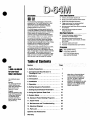 3
3
-
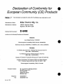 4
4
-
 5
5
-
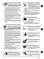 6
6
-
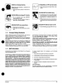 7
7
-
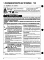 8
8
-
 9
9
-
 10
10
-
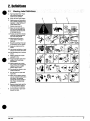 11
11
-
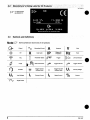 12
12
-
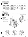 13
13
-
 14
14
-
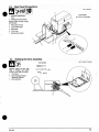 15
15
-
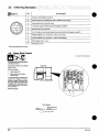 16
16
-
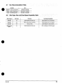 17
17
-
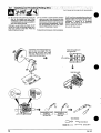 18
18
-
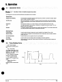 19
19
-
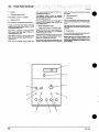 20
20
-
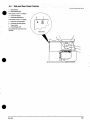 21
21
-
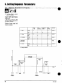 22
22
-
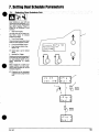 23
23
-
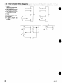 24
24
-
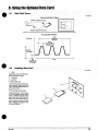 25
25
-
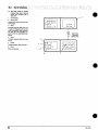 26
26
-
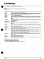 27
27
-
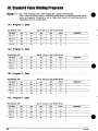 28
28
-
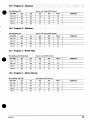 29
29
-
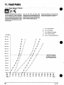 30
30
-
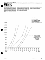 31
31
-
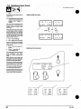 32
32
-
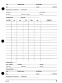 33
33
-
 34
34
-
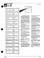 35
35
-
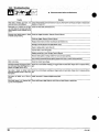 36
36
-
 37
37
-
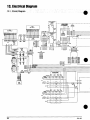 38
38
-
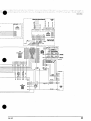 39
39
-
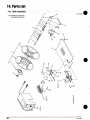 40
40
-
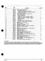 41
41
-
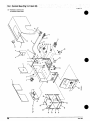 42
42
-
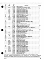 43
43
-
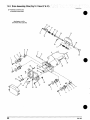 44
44
-
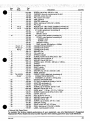 45
45
-
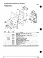 46
46
-
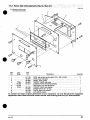 47
47
-
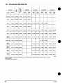 48
48
-
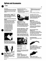 49
49
-
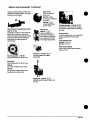 50
50
-
 51
51
-
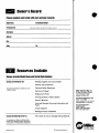 52
52


Miller KH339697 Le manuel du propriétaire
- Catégorie
- Système de soudage
- Taper
- Le manuel du propriétaire
- Ce manuel convient également à
dans d''autres langues
- English: Miller KH339697 Owner's manual
Documents connexes
-
Miller D-64M WIRE FEEDER CE Le manuel du propriétaire
-
-
-
-
-
-
-
-
-
Miller XMT 304 CC AND CC/CV CE (460 V) Le manuel du propriétaire