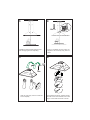
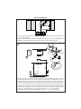
Faber CLAS30SS300B Guide d'installation
- Catégorie
- Hottes
- Taper
- Guide d'installation

CLAS30SS600-B
CLAS36SS600-B
CLAS30SS300-B
CLAS36SS300-B
Installation Instructions
Use and Care Information
Instructions d'installation
Utilisez et d'entretien
CLASSICA PLUS

2
READ AND SAVE THESE INSTRUCTIONS BEFORE YOU START
INSTALLING THIS RANGEHOOD
WARNING: - TO REDUCE THE RISK OF A RANGE TOP GREASE FIRE:
a) Never leave surface units unattended at high settings. Boilovers cause smoking and
greasy spillovers that may ignite. Heat oils slowly on low or medium setting.
A KV@XRSTQMGNNC.-VGDMBNNJHMF@SGHFGGD@SNQVGDMl@LADHMFENNCHD"QDODR
Suzette, Cherries Jubilee, Peppercorn Beef Flambé).
c) Clean ventilating fans frequently. Grease should not be allowed to accumulate on fan
NQkKSDQ
d) Use proper pan size. Always use cookware appropriate for the size of the surface element.
WARNING: - TO REDUCE THE RISK OF INJURY TO PERSONS IN THE EVENT OF A
RANGE TOP GREASE FIRE, OBSERVE THE FOLLOWING*:
@2,.3'$1%+ ,$2VHSG@BKNRDkSSHMFKHCBNNJHDRGDDSNQLDS@KSQ@XSGDMSTQMNEESGDATQMDQ
!$" 1$%4+3./1$5$-3!41-2(ESGDl@LDRCNMNSFNNTSHLLDCH@SDKX$5 "4 3$
AND CALL THE FIRE DEPARTMENT.
b) NEVER PICK UP A FLAMING PAN - You may be burned.
c) DO NOT USE WATER, including wet dishcloths or towels - a violent steam explosion will
result.
d) Use an extinguisher ONLY if:
1. You know you have a Class ABC extinguisher, and you already know how to operate it.
3GDkQDHRRL@KK@MCBNMS@HMDCHMSGD@QD@VGDQDHSRS@QSDC
3GDkQDCDO@QSLDMSHRADHMFB@KKDC
8NTB@MkFGSSGDkQDVHSGXNTQA@BJSN@MDWHS
* Based on "Kitchen Firesafety Tips" published by NFPA
WARNING - TO REDUCE THE RISK OF FIRE OR ELECTRIC SHOCK, do not use this
fan with any solid-state speed control device.
WARNING - TO REDUCE THE RISK OF FIRE, ELECTRICAL SHOCK, OR INJURY TO
PERSONS, OBSERVE THE FOLLOWING:
1. Use this unit only in the manner intended by the manufacturer. If you have any
questions, contact the manufacturer.
2. Before servicing or cleaning unit, switch power off at service panel and lock the
service disconnecting means to prevent power from being switched on acciden-
tally. When the service disconnecting means cannot be locked, securely fasten a
prominent warning device, such as a tag, to the service panel.
CAUTION: For General Ventilating Use Only. Do Not Use To Exhaust Hazardous or
Explosive Materials and Vapors.
WARNING - TO REDUCE THE RISK OF FIRE, ELECTRICAL SHOCK, OR INJURY TO
PERSONS, OBSERVE THE FOLLOWING:
1. (MRS@KK@SHNM6NQJ MC$KDBSQHB@K6HQHMF,TRS!D#NMD!X0T@KHkDC/DQRNMR(M BBNQ-
dance With All Applicable Codes And Standards, Including Fire-Rated Construction.
2. 2TEkBHDMS@HQHRMDDCDCENQOQNODQBNLATRSHNM@MCDWG@TRSHMFNEF@RDRSGQNTFG
SGDlTDBGHLMDXNEETDKATQMHMFDPTHOLDMSSNOQDUDMSA@BJCQ@ESHMF%NKKNVSGD
heating equipment manufacturer's guideline and safety standards such as those
OTAKHRGDCAXSGD-@SHNM@K%HQD/QNSDBSHNM RRNBH@SHNM-%/ @MCSGD LDQHB@M
2NBHDSXENQ'D@SHMF1DEQHFDQ@SHNM@MC HQ"NMCHSHNMHMF$MFHMDDQR 2'1 $@MC
the local code authorities.

3
ALL WALL AND FLOOR OPENINGS WHERE THE RANGEHOOD IS INSTALLED MUST
BE SEALED.
This rangehood requires at least 24" of clearance between the bottom of the rangehood
and the cooking surface or countertop. This hood has been approved by UL at this distance from
the cooktop. Overhead cabinets on both sides of this unit must be a minimum of 18" above the
cooking surface or countertop. Consult the cooktop or range installation instructions given by
the manufacturer before making any cutouts. MOBILE HOME INSTALLATION The installation
of this rangehood must conform to the Manufactured Home Construction and Safety Standards,
Title 24 CFR, Part 3280 (formerly Federal Standard for Mobile Home Construction and Safety, Title
24, HUD, Part 280). See Electrical Requirements.
• Venting system MUST terminate outside the home.
• DO NOT terminate the ductwork in an attic or other enclosed space.
• DO NOT use 4" laundry-type wall caps.
• Flexible-type ductwork is not recommended.
• DO NOTNARSQTBSSGDkNVNEBNLATRSHNM@MCUDMSHK@SHNM@HQ
q%@HKTQDSNENKKNVUDMSHMFQDPTHQDLDMSRL@XQDRTKSHM@jQD
WARNING
!
Cold Weather installations
M@CCHSHNM@KA@BJCQ@ESC@LODQRGNTKCADHMRS@KKDCSNLHMHLHYDA@BJV@QCBNKC@HQkNV@MC@
nonmetallic thermal break should be installed to minimize conduction of outside temperatures as
part of the vent system. The damper should be on the cold air side of the thermal break. The break
should be as close as possible to where the vent system enters the heated portion of the house.
VENTING REQUIREMENTS
Determine which venting method is best for your application. Ductwork can extend either through the
wall or the roof.
3GDKDMFSGNESGDCTBSVNQJ@MCSGDMTLADQNEDKANVRRGNTKCADJDOSSN@LHMHLTLSNOQNUHCDDEjBHDMS
performance. The size of the ductwork should be uniform. Do not install two elbows together. Use
CTBSS@ODSNRD@K@KKINHMSRHMSGDCTBSVNQJRXRSDL4RDB@TKJHMFSNRD@KDWSDQHNQV@KKNQkNNQNODMHMF
around the cap.
Flexible ductwork is not recommended. Flexible ductwork creates back pressure and air turbulence
that greatly reduces performance.
,@JDRTQDSGDQDHROQNODQBKD@Q@MBDVHSGHMSGDV@KKNQkNNQENQDWG@TRSCTBSADENQDL@JHMFBTSNTSR
Do not cut a joist or stud unless absolutely necessary. If a joist or stud must be cut, then a supporting
frame must be constructed.
WARNING - To Reduce The Risk Of Fire, Use Only Metal Ductwork.
" 43(.-3NQDCTBDQHRJNEkQD@MCSNOQNODQKXDWG@TRS@HQADRTQDSNCTBS@HQNTSRHCDm#N
not vent exhaust air into spaces within walls or ceilings or into attics, crawl spaces, or garages.
3. When cutting or drilling into wall or ceiling, do not damage electrical wiring and
other hidden utilities.
4. Ducted fans must always be vented to the outdoors.

4
• Electrical ground is required on this rangehood.
• If cold water pipe is interrupted by plastic, nonmetallic gaskets or other materials, DO
NOT use for grounding.
• DO NOT ground to a gas pipe.
• DO NOT have a fuse in the neutral or grounding circuit. A fuse in the neutral or
grounding circuit could result in electrical shock.
q"GDBJVHSG@PT@KHjDCDKDBSQHBH@MHEXNT@QDHMCNTAS@RSNVGDSGDQSGDQ@MFDGNNCHR
properly grounded.
q%@HKTQDSNENKKNVDKDBSQHB@KQDPTHQDLDMSRL@XQDRTKSHM@jQD
WARNING

5
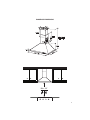
RANGEHOOD DIMENSIONS
Min. 24"

6
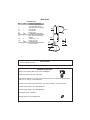
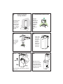
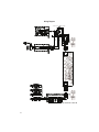
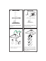
MAIN PARTS
Components
Ref. Qty. Product Components
1 1 Hood Body, complete with: Con-
trols, Light, Filters, Blower.
2 1 Telescopic Chimney comprising:
2.1 1 Upper Section
2.2 1 Lower Section
10 1 Damper ø 5 7/8"
Ref. Qty. Installation Components
7.2.1 2 Upper Chimney Section Fixing
Brackets
12a 8 Screws 3/16" x 1 3/4"
12b 6 Screws 1/8" x 3/8"
Qty. Documentation
1 Instruction Manual
1
2.2
2.1
10
7.2.1
12b
Available Accessories
Direct Connect Wiring Box sku # number: WIREBOX
Activated Charcoal Filter sku # FILTER1
+LJK&HLOLQJ&KLPQH\.LW8SSHUDQG/RZHU&KLPQH\)OXHWRUHSODFHWKHRULJLQDOÀXHV
WR¿WXSWRFHLOLQJVVNX+,*+&/3/
'XFWOHVV.LW,QFOXGHV'XFWOHVV'LYHUWHU7ZR&KDUFRDO)LOWHUVVNX'8&7&/3/
0DNH8S$LU'DPSHU.LW08'$03(5
0DNH8S$LU'DPSHU.LW08'$03(5
CFM Reducer Kit - CFMRED
Wireless Remote Control-REMCTRL
Parts needed
- 6" Round Metal ductwork .
12a

7
Choose your ducting method
Non Ducted - Recirculation OptionDucted Venting Options Installation
Requires
purchase of
Activated
Charcoal
Accessory
Horizontal
Vertical
6"
H
I
Install Damper that is included with the Hood
before connecting to the ductwork.
Only for Ducted Venting Installation

8
1
2
5
6
3
4
21
6
5
6
3
4
21
6
1 2
3 4
5 6
7 1/16 ”
5 1/2”
´
>
´
5 1/2”
24”
24”
7.2.1
2.1
2.1
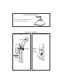
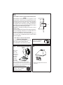
Draw a vertical line on the supporting wall as high as practical, at the center of the area in which
the hood will be installed.
'UDZDKRUL]RQWDOOLQHDWZKHUHWKHERWWRPHGJHRIWKHKRRGZLOOEHORFDWHGDVLQGLFDWHGLQWKH¿JXUH
that is a minimum of 24" above cooking surface.
Draw a horizontal line where indicated at the bottom edge of the vent hood at the desired height above
the cooking surface.
3ODFHDEUDFNHWRQWKHZDOODVVKRZQDERXW1/8" from the ceiling or upper limit, aligning the
centers(notch) with the vertical reference line and mark the wall at the centers of the holes in the bracket.
3ODFHWKHVHFRQGEUDFNHWRQWKHZDOODVVKRZQEHORZWKH¿UVWEUDFNHWDWWKHKHLJKWRIWKH
upper chimney section supplied and aligning the centers(notch) with the vertical line.
Mark the wall at the centers of the holes in the bracket and mark the point 1 and 2 for the Hood Body
LQVWDOODWLRQDVVKRZIURPWKHKRUL]RQWDOOLQHDQG1/2" from the vertical line).
'ULOO¡KROHVDWDOOWKHFHQWHUVSRLQWVPDUNHGSRLQWDVVKRZQ
Installation Instructions

9
L = 2x
OK!
3/16 “
I = 6x
3
4
5
6
12a
L
I
12a
11
x2
Ø
8
mm
x2
x2
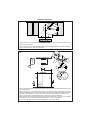
Installation screws provided must be secured
with wall plugs (purchase separately).
Insert not completely the two screws 12a
VXSSOLHGLQWKHKRRGERG\¿[LQJKROHVDV
shown.
Hook the hood body onto the screws and
screw completely.
From inside the Hood body, mark the security
hole, GULOO¡ZKHUHPDUNHGLnsert 2 wall
SOXJVLQWKHKROHVDQG¿[ZLWKVFUHZV

10
2.1
2.2
7
9
10
8
15
Slightly widen
the two sides
of the upper
chimney and
hook them
behind the
brackets 7.2.1,
making sure
that they are
well seated.
Secure the sides to the brackets by using the 4
screws 12b.
Only for the
recirculation
YHUVLRQSXVK¿W
the connection
Ductless Divert-
er (purchased
separately)
onto the
hood body air
outlet.
12
Fix the bracket
7.2.1 using the
screws 12a
supplied.
11
Slightly widen the two
sides of the lower section
and hook them between
the upper section and the
wall, making sure that they
are properly housed.
Install Roof or Wall
Cap purchased
separately. Con-
nect the 6" metal
ductwork to the
Roof or Wall Cap
and then attach
ductwork.
Vertical or Horizontal
Ducting Installation
Non-Ducted Recirculation Option
L = 4x
12a
N = 4x
12b
2.1

11
15
14
5
W
5HSODFHWKHJUHDVH¿OWHUVUHPRYHG
previously.
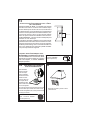
Direct Connect Wiring Box
Accessory sku # WIREBOX
(purchased separately)
ELECTRICAL INSTALLATION WITH CONNECTION
CABLE
*5281',1* ,16758&7,216 7KLV DSSOLDQFH PXVW
be grounded. In the event of an electrical short circuit,
grounding reduces the risk of electric shock by providing
an escape wire for the electric current. This appliance
is equipped with a cord having a grounding wire with a
grounding plug. The plug must be plugged into an outlet
that is properly installed and grounded.
:$51,1*,PSURSHUJURXQGLQJFDQUHVXOWLQDULVNRI
electric shock.
&RQVXOWDTXDOL¿HGHOHFWULFLDQLIWKHJURXQGLQJLQVWUXFWLRQV
are not completely understood, or if doubt exists as to
whether the appliance is properly grounded.
Do not use an extension cord. If the power supply cord
LVWRRVKRUWKDYHDTXDOL¿HGHOHFWULFLDQLQVWDOODQRXWOHW
near the appliance.
ELECTRICAL INSTALLATION WITH
OPTIONAL WIRING BOX
)RU3HUPDQHQWZLULQJ,QVWDOODWLRQ8VHRQO\
with Listed rangehood Wiring Box kit
sku # WIREBOX, manufactured by Faber.
Max. 33 7/16”
For Non-Ducted Recirculation
Option
Required Activated Charcoal Filter
Accessory - sku # - FILTER1
(purchased separately)
Attach each
charcoal
¿OWHUWRWKH
black grid on
each side of
the blower.
3UHVVWKH
charcoal
¿OWHUWLJKWO\
to the black
JULGRQWKHEORZHUVLGHDQGURWDWHWKH¿OWHU
clockwise (towards the front of the hood) until it
locks into place. Turn counterclockwise (towards
the back of the hood) to remove.
13

12
USE AND CARE INFORMATION
T1. Fan Off Button:Turn the blower Off. The fan can be operated by pressing any of the fan setting
buttons.
+ROGGRZQWKLVEXWWRQIRUVHFRQGVWRDFWLYDWH'HOD\2IIIXQFWLRQZKLFKZLOONHHSWKHIDQ2QIRU
minutes and automatically shut Off.
T2)DQ6HWWLQJV%XWWRQV/RZ6SHHG
T3)DQ6HWWLQJV%XWWRQV0HGLXP6SHHG
T4)DQ6HWWLQJV%XWWRQV+LJK6SHHG,QWHQVLYH6SHHG
+ROGGRZQWKHEXWWRQIRUVHFRQGVWRDFWLYDWHWKH,17(16,9(63(('ZKLFKLVWLPHGWRUXQIRU
PLQXWHV$WWKHHQGRIWKLVWLPHLWZLOODXWRPDWLFDOO\UHWXUQWRWKHVSHHGVHWEHIRUH6XLWDEOHWRGHDO
with maximum levels of cooking fumes.
If you hold this button down for 2 seconds when the hood is off, then after 2 minutes the motor will
shut off.
L /LJKW%XWWRQ2Q'LP2IIVZLWFKIRUWKHKDORJHQOLJKWV3UHVVWKH/,*+7EXWWRQWRWXUQWKHOLJKWRQ
again to set the lights to dimmer, and again to turn off.
LT1 T2 T3 T4
For Best Results
6WDUWWKHUDQJHKRRG VHYHUDOPLQXWHV EHIRUH FRRNLQJWR GHYHORS SURSHUDLUÀRZ$OORZ WKH
rangehood to operate for several minutes after cooking is complete to clear all smoke and
odors from the kitchen.

13
• Remove grease filters.
• Screw the Frame into place
12f, re-
LED LIGHTING UNIT
• LED lights must be replaced by Faber factory authorized
service.
"KD@MHMFLDS@KFQD@RDkKSDQR
7KHPHWDOJUHDVH¿OWHUVFDQEHFOHDQHGLQKRWGHWHUJHQW
solution or washed in the dishwasher. They should be
cleaned every 2 months, or more frequently if use is
particularly heavy.
• 5HPRYHWKH¿OWHUSXVKLQJWKHOHYHUWRZDUGVWKH
back of the unit and at the same time pulling
downward.
• :DVKWKH¿OWHUZLWKRXWEHQGLQJLWOHDYHLWWRGU\
thoroughly before replacing (if the surface of
WKH¿OWHUFKDQJHVFRORURYHUWLPHWKLVZLOOKDYH
DEVROXWHO\QRHIIHFWRQLWVHI¿FLHQF\
• Replace, taking care to ensure that the
handle faces forward.
• &OHDQLQJLQGLVKZDVKHUPD\GXOOWKH¿QLVK
RIWKHPHWDOJUHDVH¿OWHU
Replacing Activated Charcoal Filter
The Activated Charcoal Filters are not washable
and cannot be regenerated, and should be
replaced approximately every 4 months of
operation, or more frequently with heavy usage.
• 5HPRYHWKHFKDUFRDO¿OWHUE\URWDWLQJLWFORFNZLVH
backwards) until it unlocks from the motor housing
and pull off sideways.
• 7RUHLQVHUWHDFKFKDUFRDO¿OWHUSODFHXSDJDLQVW
the side of the blower and push it inward. Then
WXUQWKHFKDUFRDO¿OWHUFORFNZLVHIRUZDUGXQWLOLW
¿WVLQWRSODFH
5
W

14
Wiring Diagram
991.0379.495 H90_285 r1

15
January 4, 2016
FABER CONSUMER WARRANTY & SERVICE
All Faber products are warranted against any defect in materials or workmanship for the original purchaser
for a period of 1 year from the date of original purchase (requires proof of purchase). This warranty covers
labor and replacement parts. Faber, at its option, may repair or replace the product or components
necessary to restore the product to good working condition. To obtain warranty service, contact the dealer
from whom you purchased the range hood, or the local Faber distributor. If you cannot identify a local Faber
distributor, contact us at (508) 358-5353 for the name of a distributor in your area.
The following is not covered by Faber's warranty:
1. Service calls to correct the installation of your range hood, to instruct you how to use your range hood, to
replace or repair house fuses or to correct house wiring or plumbing.
2. Service calls to repair or replace range hood light bulbs, fuses or filters. Those consumable parts are
excluded from warranty coverage.
3. Repairs when your range hood is used for other than normal, single-family household use.
4. Damage resulting from accident, alteration, misuse, abuse, fire, flood, acts of God, improper installation,
installation not in accordance with electrical or plumbing codes or Faber documentation, or use of products
not approved by Faber.
5. Replacement parts or repair labor costs for units operated outside the United States or Canada, including
any non-UL or C-UL approved Faber range hoods.
6. Repairs to the hood resulting from unauthorized modifications made to the range hood.
7. Expenses for travel and transportation for product service in remote locations and pickup and delivery
charges. Faber range hoods should be serviced in the home.
THIS WARRANTY DOES NOT ALLOW RECOVERY OF INCIDENTAL OR CONSEQUENTIAL DAMAGES, INCLUDING, WITHOUT
LIMITATION, DIRECT, INDIRECT, INCIDENTAL, SPECIAL OR CONSEQUENTIAL DAMAGES, PERSONAL INJURY/WRONGFUL
DEATH OR LOST PROFITS FABER WARRANTY IS LIMITED TO THE ABOVE CONDITIONS AND TO THE WARRANTY PERIOD
SPECIFIED HEREIN AND IS EXCLUSIVE. EXCEPT AS EXPRESSLY SPECIFIED IN THIS AGREEMENT, FABER DISCLAIMS ALL
EXPRESS OR IMPLIED CONDITIONS, REPRESENTATIONS, AND WARRANTIES INCLUDING, WITHOUT LIMITATION, ANY
IMPLIED WARRANTIES OF MERCHANTABILITY OR FITNESS FOR A PARTICULAR PURPOSE
.
This warranty gives you specific legal rights that may vary from state to state.
Model#: ______________________________ Serial #: _____________________________

16
VEUILLEZ LIRE ET CONSERVER LA PRÉSENTE NOTICE AVANT DE
COMMENCER L'INSTALLATION DE LA HOTTE DE CUISINE
AVERTISSEMENT:-POUR RÉDUIRE LE RISQUE D'UN FEU DE GRAISSE SUR LA TABLE DE
"4(22.-Ů
a) Ne laissez jamais sans surveillance les éléments de la surface de cuisson à température élevée.
Les bouillonnements excessifs peuvent provoquer de la fumée et les débordements de graisse
ODTUDMSRfDMl@LLDQ+fGTHKDCNHSģSQDBG@TEEĢDKDMSDLDMSĒTMDSDLOĢQ@STQDA@RRDNTLNXDMMD
b) Assurez-vous de toujours mettre en marche le ventilateur de la hotte lorsque vous cuisinez
ĒSDLOĢQ@STQDĢKDUĢDNTOQĢO@QDYTMLDSRl@LAĢODWBQģODR2TYDSSDBDQHRDRITAHKĢATE
l@LAĢ
c) Nettoyez régulièrement les ventilateurs d'aspiration. Assurez-vous de ne pas laisser de la graisse
Rf@BBTLTKDQRTQKDUDMSHK@SDTQNTKDkKSQD
C4SHKHRDYSNTINTQRCDRONģKDRDSB@RRDQNKDRCDK@S@HKKD@OOQNOQHĢD4SHKHRDYSNTINTQRCDRTRSDMRHKDR
de cuisine de la taille adaptée à celle de l'élément chauffant.
5$13(22$,$-3Ů/.41/1Í5$-(1+$2!+$2241$2$-" 2#$%$4#$&1 (22$241+
3 !+$#$"4(22.-24(5$9+$21$".,, -# 3(.-224(5 -3$2Ů
a) ÉTOUFFEZ LES FLAMMES à l'aide d'un couvercle hermétique, d'une plaque à biscuits ou d'un
plateau métallique, puis éteignez le brûleur. FAITES ATTENTION AUX BRÛLURES. Si le feu ne
s'éteint pas immédiatement, QUITTEZ LES LIEUX ET APPELEZ LES POMPIERS.
b) NE PRENEZ JAMAIS UNE CASSEROLE EN FLAMME - Vous pourriez vous brûler.
c) N'UTILISEZ JAMAIS DE L'EAU, ni un linge à vaisselle ou un torchon mouillé, pour éteindre le feu.
Cela pourrait provoquer une violente explosion de vapeur.
C4SHKHRDYTMDWSHMBSDTQ4-(04$,$-3RHŮ
5NTRģSDRBDQS@HMPTfHKRf@FHSCfTMDWSHMBSDTQCDBK@RRD !"DSPTDUNTRBNMM@HRRDYAHDMRNM
mode d'emploi.
2. Le feu est de faible intensité et se limite à l'endroit où il a démarré.
3. Les pompiers ont déjà été appelés.
4MDUNHDCDRNQSHDRDSQNTUDCDQQHġQDUNTRODMC@MSPTDUNTRĢSDHFMDYKDRl@LLDR
#e@OQĠRKDFTHCDgŰ*HSBGDM%HQDR@EDSX3HORŰuOTAKHġO@QK@-%/ @TWÍS@SR4MHR
AVERTISSEMENT - POUR RÉDUIRE LE RISQUE D'INCENDIE OU DE CHOC ÉLECTRIQUE, n'utilisez
jamais ce ventilateur en association avec un dispositif de réglage de vitesse à semi-conducteurs.
AVERTISSEMENT - POUR RÉDUIRE LES RISQUES D'INCENDIE, DE CHOC ÉLECTRIQUE OU DE
!+$2241$".1/.1$++$1$2/$"3$9+$2(-2314"3(.-224(5 -3$2Ů
1. Utilisez cet appareil uniquement de la façon prévue par le fabricant. Pour toute question, com-
muniquez avec le fabricant.
2. Avant de procéder à l'entretien ou au nettoyage de l'appareil, coupez l'alimentation au niveau du
panneau électrique et verrouillez-le pour vous assurer que l'électricité n'est pas rétablie accidentel-
KDLDMS2fHKMfDRSO@RONRRHAKDCDUDQQNTHKKDQKDCHRONRHSHECfHMSDQQTOSHNMCDKf@KHLDMS@SHNM@EkBGDYCD
façon ferme et bien visible un avis de danger, par exemple à l'aide d'une étiquette sur le panneau.
33$-3(.-Ů#DRSHMĢĒTMTR@FDCDUDMSHK@SHNMFĢMĢQ@KDTMHPTDLDMS-fTSHKHRDYO@RBDCHRONRHSHE
pour l'aspiration de vapeurs ou de matériaux dangereux ou explosifs.
AVERTISSEMENT - POUR RÉDUIRE LES RISQUES D'INCENDIE, DE CHOC ÉLECTRIQUE OU DE
!+$2241$".1/.1$++$1$2/$"3$9+$2(-2314"3(.-224(5 -3$2Ů
1. +fHMRS@KK@SHNMDSKDAQ@MBGDLDMSĢKDBSQHPTDCNHUDMSģSQDQĢ@KHRĢRO@QTMSDBGMHBHDMPT@KHkĢDS
conformément à tous les codes et normes en vigueur, incluant ceux concernant la construction
à l'épreuve du feu.
2. kMCDF@Q@MSHQTMDBNLATRSHNMDSTMDĢU@BT@SHNM@CĢPT@SDRCDRF@YO@QKDRBNMCTHSDRCDK@
cheminée des appareils à combustion, une bonne aération est nécessaire pour éviter le refou-
lement. Respectez les lignes directrices fournies par le fabricant du matériel chauffant, ainsi que
KDRMNQLDRCDRĢBTQHSĢBNLLDBDKKDROTAKHĢDRO@QK@-@SHNM@K%HQD/QNSDBSHNM RRNBH@SHNM-%/
DSK@ LDQHB@M2NBHDSXENQ'D@SHMF1DEQHFDQ@SHNM@MC HQ"NMCHSHNMHMF$MFHMDDQR 2'1 $@TW
États-Unis, ainsi que les codes en vigueur dans votre région.

17
3. Lorsque vous faites une ouverture ou percez dans un mur ou le plafond, veillez à ne pas en-
CNLL@FDQKDRkKRĢKDBSQHPTDRNTCf@TSQDRCHRONRHSHERB@BGĢR
4. +DRUDMSHK@SDTQRB@M@KHRĢRCNHUDMSSNTINTQRģSQDQ@BBNQCĢRĒKfDWSĢQHDTQ
3.43$.45$1341$# -2+$,41.4+$/+ -"'$1½/1.7(,(3Í#$+
'.33$#.(3Î31$2"$++Í$
Un espace libre d'au moins 24 " est requis entre le bas de la hotte et la surface de
BTHRRNMNTKDBNLOSNHQ"DSSDGNSSD@ġSġGNLNKNFTġDO@QKe4+ĐBDSSDCHRS@MBDCDK@
RTQE@BDCDBTHRRNM+DR@QLNHQDRRTRODMCTDRCDBG@PTDBŃSġCDKe@OO@QDHKCNHUDMSRD
SQNTUDQĐ@TLNHMRŭCDK@RTQE@BDCDBTHRRNMNTCTBNLOSNHQ"NMRTKSDYK@MNSHBD
d'installation de la surface de cuisson ou de la hotte fournie par le fabricant avant de
pratiquer des ouvertures. INSTALLATION DANS UNE MAISON MOBILE L'installation
CDBDSSDGNSSDCNHSĢSQDBNMENQLDĐK@/@QSHDCDK@MNQLD,@MTE@BSTQDC'NLD
"NMRSQTBSHNM@MC2@EDSX2S@MC@QCR3HSKD"%1OQġBġCDLLDMSK@O@QSHDCDK@
norme Federal Standard for Mobile Home Construction and Safety, Title 24, HUD).
"NMRTKSDYK@jBGDSDBGMHPTDġKDBSQHPTD
q+DRXRSĠLDCDUDMSHK@SHNM#.(3CġANTBGDQĐKeDWSġQHDTQ
• NE FAITES PASCġANTBGDQKDRBNMCTHSRC@MRTMFQDMHDQNTTM@TSQDDMCQNHSEDQLġ
• N'UTILISEZ PASTMBK@ODSCDRġBGDTRDLTQ@KCDŰON
q(KMeDRSO@RQDBNLL@MCġCeTSHKHRDQCDRBNMCTHSRkDWHAKDR
• N'ENTRAVEZ PASKDkTWCDKe@HQCDBNLATRSHNMDSCDUDMSHK@SHNM
• Le non-respect des exigences en matière de ventilation pourrait entraîner un incendie.
AVERTISSEMENT
!
Installation dans les climats froids
+DRXRSĠLDCDUDMSHK@SHNMCNHSOQġUNHQTMQDFHRSQD@MSHQDENTKDLDMSRTOOKġLDMS@HQDONTQQġCTHQDKD
kTWCe@HQEQNHCHMUDQRD@HMRHPTeTMDA@QQHĠQDSGDQLHPTDMNMLġS@KKHPTDONTQQġCTHQDK@BNMCTBSHNM
CDRSDLOġQ@STQDRDWSġQHDTQDR+DQDFHRSQDCNHSĢSQDHMRS@KKġCTBŃSġ@HQEQNHCO@QQ@OONQSĐK@A@QQHĠQD
SGDQLHPTD+@A@QQHĠQDSGDQLHPTDCNHSĢSQDONRHSHNMMġDKDOKTROQĠRPTDONRRHAKDCDKeDMCQNHSNŔKD
RXRSĠLDCDUDMSHK@SHNMOġMĠSQDC@MRK@O@QSHDBG@TEEġDCDK@L@HRNM
CRITÈRES DE VENTILATION
#ġSDQLHMDYPTDKKDLġSGNCDCDUDMSHK@SHNMDRSLHDTW@C@OSġDĐUNSQD@OOKHB@SHNM+DRBNMCTHSRODTUDMS
passer par le mur ou le toit.
/NTQF@Q@MSHQTMDLDHKKDTQDDEjB@BHSġK@KNMFTDTQCDRBNMCTHSRDSKDMNLAQDCDBNTCDRCNHUDMSĢSQDKDOKTR
KHLHSġRPTDONRRHAKD+DCH@LĠSQDCDRBNMCTHSRCDUQ@HSĢSQDTMHENQLD-eHMRS@KKDYO@RCDTWBNTCDRDMRDLAKD
4SHKHRDYTMQTA@MONTQB@M@KHR@SHNMR@jMCDRBDKKDQSNTRKDRINHMSRCTRXRSĠLDCDBNMCTHSR4SHKHRDYTMB@KEDT-
SQ@FDONTQRBDKKDQKDRNTUDQSTQDRC@MRKDLTQDWSġQHDTQNTKDOK@MBGDQ@TSNTQCTBK@ODS
Il n'est pas recommandé d'utiliser des conduits flexibles. Les conduits flexibles provoquent une contre-pression
et de la turbulence qui diminuent grandement l'efficacité de l'appareil.
RRTQDYUNTRPTDKeDRO@BDKHAQDC@MRKDLTQNTKDOK@MBGDQDRSRTEjR@MSONTQKDBNMCTHSCeġU@BT@SHNM@U@MSCD
OQ@SHPTDQKDRNTUDQSTQDR-DBNTODYI@L@HRTMDONTSQDNTTMBGDUQNMR@TERHBeDRS@ARNKTLDMSMġBDRR@HQD
2eHKRe@UĠQDMġBDRR@HQDCDBNTODQTMDONTSQDNTTMBGDUQNMK@BNMRSQTBSHNMCeTMQDMENQBDLDMSDRSQDPTHRD
AVERTISSEMENT - Pour réduire le risque d'incendie, utilisez uniquement des conduits métalliques.
ATTENTION - Pour réduire le risque d'incendie et pour évacuer adéquatement l'air, assurez-vous
CDQ@BBNQCDQKDRBNMCTHSRĒKfDWSĢQHDTQm-DCHEETRDYO@RKf@HQCfĢU@BT@SHNMC@MRCDRDRO@BDRĒ
l'intérieur des murs ou du plafond, ou encore à l'intérieur d'un grenier, d'une galerie technique
ou d'un garage.

18
q4MDLHRDĐK@SDQQDġKDBSQHPTDDRSQDPTHRDONTQBDSSDGNSSD
q-e43(+(2$9/ 2TMSTX@TCeD@TEQNHCDONTQK@LHRDĐK@SDQQDRHBDKTHBHDRSAQ@MBGġO@QCDR
INHMSRDMOK@RSHPTDO@QCDRQNMCDKKDRMNMLġS@KKHPTDRNTCe@TSQDRL@SġQH@TW
q-e43(+(2$9/ 2TMDBNMCTHSDCDF@YONTQK@LHRDĐK@SDQQD
q-e(-23 ++$9/ 2TMETRHAKDRTQKDBHQBTHSMDTSQDNTKDBHQBTHSCDLHRDĐK@SDQQD+@OQġRDMBD
CeTMETRHAKDC@MRKDBHQBTHSMDTSQDNTCDLHRDĐK@SDQQDODTSDMSQ@ıMDQTMBGNBġKDBSQHPTD
q"NMRTKSDYTMġKDBSQHBHDMPT@KHjġRHUNTRMeĢSDRO@RBDQS@HMCDK@LHRDĐK@SDQQDCDK@GNSSD
q+DMNMQDRODBSCDRDWHFDMBDRCDK@jBGDSDBGMHPTDġKDBSQHPTDONTQQ@HSDMSQ@ıMDQTMHMBDMCHD
AVERTISSEMENT

19
Min. 24"
DIMENSIONS DE LA HOTTE

20
PIÈCES PRINCIPALES
Composants
Réf. Qté Composants du produit
1 1 Bâti de la hotte, avec : Com-
PDQGHVpFODLUDJHV¿OWUHVYHQWLODWHXU
2 1 Cheminée télescopique comprenant :
2.1 1 Section supérieure
2.2 1 Section inférieure
10 1 Registre ø 5 7/8"
Réf. Qté Composants d'installation
%ULGHVGH¿[DWLRQGHODVHFWLRQ
supérieure de la cheminée
12a 8 Vis 3/16" x 1 3/4"
12b 6 Vis 1/8" x 3/8"
Qté Documentation
1 Mode d'emploi
1
2.2
2.1
10
7.2.1
12b
Accessoires disponibles
%RvWLHUGHFRQQH[LRQGLUHFWHQRGDUWLFOH:,5(%2;
1RGDUWLFOH)LOWUHjFKDUERQDFWLIFILTER1
Trousse de cheminée pour plafonds hauts - Conduit de cheminée supérieur et inférieur
SRXUUHPSODFHUOHFRQGXLWRULJLQDOSRXUSODIRQGVMXVTXj1RGDUWLFOH+,*+&/3/
7URXVVHVDQVFRQGXLW&RPSUHQGGpÀHFWHXUGHUHF\FODJHGHX[¿OWUHVjFKDUERQ1R
GDUWLFOH'8&7&/3/
'LVSRVLWLIGDSSRUWGDLU08'$03(5
'LVSRVLWLIGDSSRUWGDLU08'$03(5
Réducteur de débit - CFMRED
7pOpFRPPDQGHVDQV¿O5(0&75/
Pièces requises
- Conduit métallique 6" circulaire.
12a
La page charge ...
La page charge ...
La page charge ...
La page charge ...
La page charge ...
La page charge ...
La page charge ...
La page charge ...
La page charge ...
La page charge ...
La page charge ...
La page charge ...
-
 1
1
-
 2
2
-
 3
3
-
 4
4
-
 5
5
-
 6
6
-
 7
7
-
 8
8
-
 9
9
-
 10
10
-
 11
11
-
 12
12
-
 13
13
-
 14
14
-
 15
15
-
 16
16
-
 17
17
-
 18
18
-
 19
19
-
 20
20
-
 21
21
-
 22
22
-
 23
23
-
 24
24
-
 25
25
-
 26
26
-
 27
27
-
 28
28
-
 29
29
-
 30
30
-
 31
31
-
 32
32


Faber CLAS30SS300B Guide d'installation
- Catégorie
- Hottes
- Taper
- Guide d'installation
dans d''autres langues
Documents connexes
-
Faber TRAT30SS600B Guide d'installation
-
Faber LEVL36SS400 Guide d'installation
-
-
-
-
-
-
-
-

