Fulgor Milano F7DP30W1 Guide d'installation
- Catégorie
- Fours
- Taper
- Guide d'installation
Ce manuel convient également à

OVENS
SERIES 700
INSTALLATION INSTRUCTIONS
INSTRUCTIONS D’INSTALLATION
INSTRUCCIONES PARA LA INSTALACIÓN


Dear Customer,
Thank you for purchasing a Fulgor Milano product. Fulgor Milano is
committed to excellence and our signature technologies provide you with
professional tools for your kitchen. One of our central philosophies is
continuous investment in research that is rooted in developing life enhancing
technology. Our goal is to deliver products that are worthy of your family
recipes and that will breathe life into your kitchen, the heart of your home.
We invite you to enjoy your new Fulgor Milano product with same amount
of care and attention that we have put into creating it.
Your Life | Our Passion


EN
1
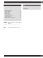
TABLE OF CONTENTS PAGE
Introduction 2
Tools you will need 2
Power requirements 2
Choosing oven location 2
Steps for installation 2
Installation notes 3
Electrical supply 7
Wiring requirements 7
Connecting to 208 volt circuit 8
Electrical connections 9
3-Wire branch circuit (for US only) 9
4-Wire branch circuit (for US and Canada) 9
Final checklist 10
IMPORTANT: Save these instructions for the local electrical
inspector use.
INSTALLER: Please leave this manual with owner for future
reference.
OWNER: Please keep this manual for future reference.
WARNING
If the information in this manual is not followed exactly, a fire
or explosion may result causing property damage, personal
inju ry or death.

EN
2
Introduction
Please read these instructions COMPLETELY AND CAREFULLY.
They will save you time and effort and help to ensure optimum
oven performance.
Be sure to observe all WARNINGS. These installation
instructions are intended for use by a qualified installer.
In addition to these instructions, the oven shall be installed:
• In the United States, in accordance with the National Electric
Code/State and Municipal codes and/or local codes.
• In Canada, in accordance with Canadian Electric Code
C22.1-latest edition/Provincial and Municipal codes and/
or local codes.
These shall be carefully followed at all times.
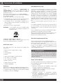
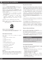
NOTE: If installing your oven in canada please check to make
sure that you have a model with the us and canadian
listing
Mark, as shown above:
Mark as shown above means the oven complies with both US
and CANADIAN Standards.
Tools you will need
The following tools are needed to install your new oven:
• Tape measure and straightedge or ruler
• Pencil
• Phillips screwdriver
• Level
• Wire cutters and wire stripper
• Hand or saber saw
• 1” (2,5cm) Hole saw
• Drill and drill bit
• Safety gloves and goggles
• Volt meter (0-250VAC)
Packaging
Remove all tape and packaging before using the oven.
Destroy the packaging after unpacking the oven following the
rules in force in your town. Never allow children to play with
packaging material.
Power requirements
The oven must be supplied with the proper voltage and
frequency. The oven is manufactured to be connected to a
three-wire or four-wire, single phase, 120/240 Volt, 60 Hz AC
electrical supply on a separate circuit fused on both sides of the
line. If a 120/208 Volt circuit must be used, see Connecting to
120/208 Volt Circuit, in this manual.
A circuit breaker or time delay fuse, sized not to exceed
the circuit rating of the appliance specified on the rating
plate located on the frame behind the door of the oven is
recommended (see figure at page 4).
The oven must be supplied with copper or alumimum wires.
If aluminum wire is provided to connect oven to branch circuit,
UL listed connectors for joining copper and aluminum must be
used. Follow instructions provided with connectors.
It is recommended that you have the electrical wiring and hook-
up of your oven performed by a qualified electrician.
After installation is complete have the electrician show you
where the main disconnect is and which of the circuit breakers/
fuses are for the oven.
Choosing oven location
Carefully select the location where the oven will be placed.
The oven should be located for convenient use in the kitchen,
but away from strong drafts.
Strong drafts may be caused by open doors or windows, or
by heating and/or air conditioning vents or fans. Make sure
that electrical power can be provided to the location selected.
WARNING
If installed at an ambient temperature of less than 37°F (3°C),
the oven may present error F*0117. When the oven reaches
a higher ambient temperature, the error will disappear.
Steps for installation
The following pages provide the necessary information for
proper installation of the oven and are arranged as follows:
• Technical Data
• Installation Cutout Dimensions, Required Clearances and
Mounting instructions for:
- Under counter Installation, Single Oven
- Wall Installation, Single Oven
- Wall Installation, Double Oven
• Electrical Supply and Wiring Requirements, Programming
required if connecting to 120/208 Volt Circuit. Electrical
Connections for 3-wire or 4-wire Branch Circuit.
• Final Checklist
Installation Instructions

EN
3
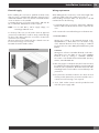
Installation Instructions
Installation notes
1. Do not slide oven across floor. Damage to floor covering or
floor could result.
2. The oven support surface must be a minimum 3/4” (2cm)
thick plywood platform.
For single ovens, it must support 202 pounds.
For double ovens, it must support 379 pounds. The
platform must be solid, level and flush with the bottom of
the cabinet cut out.
3. Use extreme caution when moving or installing the oven. It
is very heavy.
DO NOT LIFT THE OVEN BY THE DOOR HANDLE, remove
the door for easier handling and installing.
See REMOVING THE DOOR in the maintenance section of
the Use Care Manual.
4. Be very careful when moving or installing the oven to avoid
damage to the oven frame or damage to the cabinets.
5. Be sure to level the oven. An oven that is not level may
provide poor or inconsistent baking results.
6. Be careful when placing oven. DO NOT pinch the conduit
between the oven back.
WARNING
Before installing or removing, turn power OFF at the service
panel. Lock service panel to prevent power from being
turned ON accidentally.
Securely fasten oven to cabinet using the screws provided.
Failure to do so could result in oven moving or tipping during
use and causing damage to the oven or cabinets or personal
injury.
Know how to disconnect the power to the oven at the circuit
breaker or fuse box in case of an emergency.
CAUTION
Unit is heavy and requires at least two people or proper
equipment to move.
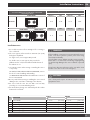
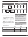
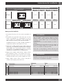
TECHNICAL DATA
For cutout dimensions see following section titled:
Preparing location
Electrical Ratings and Maximum Connected Load
@ 120/240 Volts 60 Hz @ 120/208 Volts 60 Hz
SINGLE OVEN Amperes kW Amperes kW
F7SP30*1
15.4 3.70 16.8 3.50
DOUBLE OVEN
Amperes kW Amperes kW
UPPER CAVITY LOWER CAVITY
F7DP30*1
31.2 7.50 30.3 6.30
Ltr. DIMENSION
SINGLE DOUBLE
30” 30”
A
Cutout Width 28 7/16” (72.2 cm) 28 7/16” ( 72.2 cm)
B
Cutout Depth 24” (61.0 cm) 24” ( 61.0 cm)
C
Cutout Height 27 3/8” (69.5 cm) 50” (127.0 cm)
D
Floor Bottom of Cutout 34” (86.5 cm) N/A
E
Minimum Spacing 1/2” min ( 1.3 cm) 1/2” min ( 1.3 cm)
F
Minimum Spacing 3/4” min ( 1.9 cm) 1” min ( 2.5 cm)

EN
4
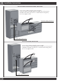
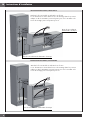
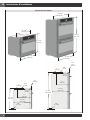
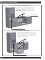
WALL OR UNDER COUNTER INSTALLATION, SINGLE OVEN
A
B
C
F
E
B
A
C
E
D
Secure oven to cabinet using the screws provided.
Screws should be inserted through the mounting holes in the positions
indicated in the frame (open door to see frame and mounting holes).
Do not over tighten screws.
Electrical supply junction box
Electrical supply junction box
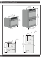
WALL INSTALLATION, DOUBLE OVEN
A
B
C
F
E
Secure oven to cabinet using the screws provided.
Screws should be inserted through the mounting holes in the positions
indicated in the frame (open door to see frame and mounting holes).
Do not over tighten screws.
Electrical supply junction box
Installation Instructions
Rimando

EN
5
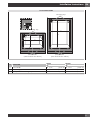
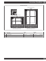
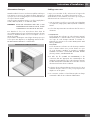
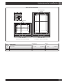
FLUSH INSTALLATION
G
G
F
H
F
Finished sides
(same finish like the cabinet)
Mounting strip
Mounting strip
Finished sides
(same finish like the cabinet)
Ltr. DIMENSION
SINGLE DOUBLE
30” 30”
F
Cutout Width 30 1/16” (76.4 cm) 30 1/16” ( 76.4 cm)
G
Cutout Height 28 1/32” (71.2 cm) 51” (129.5 cm)
H
Visible part of the mounting strips 3/4” ( 1.9 cm) 3/4” ( 1.9 cm)
Installation Instructions

EN
6
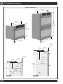
PRODUCT-DIMENSIONS
(129 cm)
50 3/4”
(75.4cm)
29 3/4”
(68 cm)
26 3/4”
23 1/8”
(58.7 cm)
17”
(43 cm)
7 7/8”
(20 cm)
(126.2 cm)
49 3/4”
3/4”
(1.9 cm)
(2 cm)
3/4”
1”
(2.5 cm)
26 3/4”
(68 cm)
27 7/8”
(70.7 cm)
(75.4 cm)
29 3/4”
23 1/8”
(58.7 cm)
17”
(43 cm)
7 7/8”
(20 cm)
3/4”
(1.9 cm)
(2 cm)
3/4”
1”
(2.5 cm)
27 1/8”
(69 cm)
7/8”
(2.2 cm)
7/8”
(2.2 cm)
Installation Instructions

EN
7
Electrical supply
Before installing the oven have a qualified electrician verify
that your home is provided with adequate electrical service
and that the addition of the oven will not overload the branch
circuit on which it is to be installed.
A separate three-wire or four-wire single phase, 240 Volt, 60
Hz, or a 208 Volt, 60Hz branch circuit is required.
NOTE: For use with 208 v, 60 hz supply voltage, see
connecting to 208 volt circuit.
For hook-up of the oven you will need to have an approved
junction box installed where it will be easily reached through
the front of the cabinet where the oven will be located. The
oven has 3 feet of conduit.
Allow two to three feet of slack in the line so that the oven can
be moved if servicing is ever necessary.
DO NOT shorten the flexible conduit.
LOCATION OF RATING PLATE
Wiring requirements
When making the wire connections, use the entire length of the
conduit provided (3 feet). The conduit must not be cut.
Before making connections make sure the power is off and
read and observe the following:
1. A separate three-wire or four-wire, single phase, 240 Volt,
60 Hz or 208 Volt, 60 Hz branch circuit is required for the
oven.
2. The oven must be connected with Copper or Aluminum wire.
3. In the United States:
Wiring must conform to the National Electrical Code,
ANSI/NFPA No. 7 latest edition. You can obtain a copy
of the National Electrical Code by writing to: National
Fire Protection Association Batterymarch Park Quincy, MA
02269
In Canada:
Wiring must conform to Canadian Electrical Code C22.1-
latest edition. You can obtain a copy of the Canadian
Electrical Code by writing to: Canadian Standards
Association 178 Rexdale Boulevard Rexdale (Toronto),
Ontario, Canada M9W 1R3
4. Wire size (Copper or Aluminum wire) and connections must
be suitable for the rating of the appliance as per the National
Electrical Code requirements. The flexible armoured cable
extending from the oven should be connected directly to the
junction box.
5. The junction box should be located so as to allow as much
slack as possible between the junction box and the oven so
it can be moved if servicing is ever required.
6. A U.L. listed conduit connector must be provided at each
end of the power supply cable.
Installation Instructions

EN
8
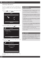
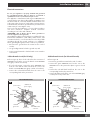
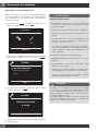
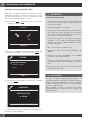
Connecting to 208 volt circuit
This option is provided for areas where standard 240 Volt
service is not available. This option must be accessed with
the oven connected to power source, and using the following
sequence:
a) Press the
SET
key and select the option by means of the
arrow and confi rm with the
START
key.
SETUP
SERVICE
b) From the “SYSTEM” menu select the “MAIN VOLTAGE”
option and confi rm again with the
START
key.
EVENT LOGS
MAIN VOLTAGE
SYSTEM
DEMO
OM 15
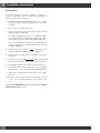
c) By means of the arrow, select the “208V” option and
confi rm with the
START
.
MAIN VOLTAGE
240
ADVANCED
The voltage setting is stored and kept even after a long
power-off.
WARNING
ELECTRICAL SHOCK HAZARD
• The electrical power to the oven branch circuit must be
shut off while line connections are being made.
• Do not use an extension cord with this appliance.
• Electrical ground is required on this appliance. The free
end of the green wire (the ground wire) must be connected
to a suitable ground. This wire must remain grounded to
the oven.
• If cold water pipe is interrupted by plastic, non metallic
gaskets, union connections or other insulating materials,
DO NOT use for grounding.
• DO NOT ground to a gas pipe.
• DO NOT have a fuse in the NEUTRAL or GROUNDING
circuit. A fuse in the NEUTRAL or GROUNDING circuit
could result in an electrical shock.
• Check with a qualifi ed electrician if you are in doubt as to
whether the appliance is properly grounded.
• Failure to follow these instructions could result in serious
injury or death.
CAUTION
Do not repair or replace any part of the appliance unless
specifi cally recommended in the manual. All other servicing
should be done by a qualifi ed technician. This may reduce
the risk of personal injury and damage to the oven.
Never modify or alter the construction of the appliance by
removing panels, wire covers, screws, or any other part of
the product.
Installation Instructions

EN
9
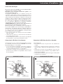
Electrical connections
Be sure your appliance is properly installed and grounded
by a qualified technician. Ask your dealer to recommend a
qualified technician or an authorized repair service.
This appliance is manufactured with a green GROUND wire
connected to the oven chassis. After making sure that the power
has been turned off, connect the flexible conduit from the oven
to the junction box using a U.L. listed conduit connector. Figures
A and B and the instructions provided below present the most
common way of connecting the ovens.
Your local codes and ordinances, of course, take precedence
over these instructions. Complete electrical connections
according to local codes and ordinances.
“WARNING” Risk of Electric Shock, frame grounded to
neutral of appliance through a link.
Grounding through the neutral conductor is prohibited for new
branch-circuit installations (1996 NEC); mobile homes; and
recreational vehicles, or in an area where local codes prohibit
grounding through the neutral conductor. For installations
where grounding through the neutral conductor is prohibited:
• Disconnect the ground from the neutral at free end of
conduit;
• Use grounding terminal or lead to ground unit; and
• Connect neutral terminal or lead to branch circuit neutral in
usual manner.
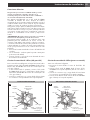
3-Wire branch circuit (for US only)
Refer to Figure A, where local codes allow the connection of
GROUND wire from the oven to the branch circuit NEUTRAL
wire (gray or white colored wire):
• If local codes permit, connect the green GROUND wire
from the oven and the white wire from the oven to the
branch circuit NEUTRAL wire (gray or white colored wire).
• Connect the red and black leads from the oven to the
corresponding leads in the junction box.
GROUNDED NEUTRAL
White wires
Cable from
power supply
Junction box
UL listed conduit
connector
Red wires
Black wires
Cable
from oven
Bare or
green wire
A
4-Wire branch circuit (for US and Canada)
Refer to Figure B:
• Disconnect ground from neutral at free end of conduit.
• Connect the green GROUND wire from the oven to the
GROUND wire in the junction box (bare or green colored
wire).
• Connect the red and black leads from the oven to the
corresponding leads in the junction box.
• Connect the white wire from the oven to the NEUTRAL (gray
or white) wire in the junction box.
UNGROUNDED NEUTRAL
Red wires
Junction box Cable from
power supply
White wires
Black wires
UL listed conduit
connector
Cable
from oven
Bare or
green wire
B
Installation Instructions

EN
10
Final checklist
To prevent improper connections leading to damage of
electrical components and so voiding the warranty, the
following steps must be performed:
1. Check the electrical requirements and make sure you have
the correct electrical supply and that the oven is properly
grounded.
2. Turn on the power supply to the oven.
3. Check power at the junction box wires using a voltmeter
having a range of 0-250 VAC.
If you have installed the oven for use on 240 Volt supply,
you should find that the voltage reading between the black
and red wires (Line to Line) should be 220 to 240 Volts.
If you have modified the oven(s) for use on 208 Volt, the
voltage reading between the black and red wires should
be 190 to 208 Volts.
4. Test the oven mode. Select the
BAKE
mode. See the Use
and Care Manual for detailed operation instructions.
5. Verify that the oven light comes on and the oven begins
to preheat.
6. Test the door lock. Set the
SELF CLEAN
mode. Confirm that
the door locks when the lock icon appears in the display.
7. If installing a double oven, test the second oven as well.
8. To check the other oven functions refer to the “Using the
Oven Controls” section of the USE AND CARE MANUAL.
9. If the oven is working properly, turn off the power supply
to the oven.
10. Place the cover on the junction box and make sure the
cover is securely fastened and turn on the power to the
oven.
Leave these INSTALLATION instructions as well as the USE AND
CARE MANUAL with the owner.
Installation Instructions

FR
1
TABLE DES MATIERES PAGE
Introduction 2
Outils necessaires 2
Alimentation necessaire 2
Choix de l’emplacement du four 2
Etapes de l’installation 2
Remarques d’installation 3
Alimentation electrique 7
Cablage necessaire 7
Connexion a un circuit de 208 volt 8
Connexions electriques 9
Connexion à 3 fils (Pour US seulement) 9
Connexion à 4 fils (Pour des US ou Canada) 9
Liste de verification finale 10
IMPORTANT: Gardez ces instructions pour une utilization
d’inspection électrique locale
INSTALLATEUR: Veuillez laisser ce manuel au propriétaire
pour de futures références.
PROPRIETAIRE: Veuillez garder ce manuel pour de futures
références.
AVERTISSEMENT
Si l’information de ce manuel n’est pas suivie exactement,
cela peut provoquer un incendie ou une explosion pouvant
entraîner des dégâts, des blessures ou la mort.

FR
2
Introduction
Veuillez lire ces instructions COMPLETEMENT ET
SOIGNEUSEMENT. Cela vous fera gagner du temps et
épargner des efforts et vous aidera à assurer les meilleures
performances du four.
Assurez-vous de bien observer tous les AVERTISSEMENTS.
Ces instructions d’installation sont conçues pour l’utilisation
d’un installateur qualifié.
En plus de ces instructions, le four doit être installé :
• Aux Etats-Unis selon le Code électrique national/de l’Etat et
les codes municipaux codes et/ou les codes locaux.
• Au Canada, selon le code électrique canadien C22.1-
dernière édition/codes provinciaux et municipaux et/ ou
les codes locaux.
Il faut toujours les suivre soigneusement.
REMARQUE: si vous installez votre four au canada verifiez
que vous avez un modele avec la marque us et
canadienne listee
La marque comme indiquee ci-dessus:
La marque comme indiquée ci-dessus signifie que le four
observe les standards américains et canadiens.
Outils necessaires
Vous aurez besoin des outils suivants pour installer votre
nouveau four :
• Mètre enrouleur et règle à tracer ou règle
• Crayon
• Tournevis Philips
• Niveau
• Cutter de fils électriques et des dénude - fil
• Scie sauteuse ou scie à main
• Scie - cloche de 1” (2,5 cm)
• Mèche et perceuse
• Gants et lunettes de sécurité
• Voltmètre (0-250VAC)
Emballage
Enlevez tous les adhésifs et emballage avant d’utiliser le four.
Détruisez tous les emballages après avoir désemballer le four
en suivant les règles d’usage de votre ville. Ne laissez jamais
les enfants jouer avec les emballages.
Alimentation necessaire
Le four doit être alimenté avec la fréquence et la tension
appropriée. Le four est fabriqué pour être branché à une
alimentation électrique triphasée ou à quatre fils, en simple
phase, 120/240 Volt, 60 Hz CA sur un circuit séparé avec
fusibles des deux côtés de la ligne. Si un circuit de 120/208
Volt doit être utilisé, voyez Connexion à un circuit de 120/208
Volt dans ce manuel. Un disjoncteur ou un dispositif de
surcharge dont la taille n’excède pas la valeur du circuit de
l’appareil spécifié sur la plaque de valeurs située sur le cadre
derrière la porte du four est recommandé (voir figure à la page
4).
Le four ne doit être branché qu’avec des fils de cuivre ou
aluminium.
Si un câble en aluminium est fourni pour la connection du four
au circuit électrique, il est nécessaire utiliser les connecteurs
énumérés par UL. Suivez les instructions fournies avec les
connecteurs.
Il est recommandé que vous ayez un branchement électrique
parfaitement raccordé par un électricien qualifié.
Après tout avoir installé, l’électricien doit vous montrer où est
le débranchement principal et quels sont les fusibles et le
disjoncteur et les fusibles pour le four.
Choix de l’emplacement du four
Choisissez précautionneusement l’emplacement du four.
Le four doit être situé pour un usage approprié dans la cuisine,
mais toujours loin de courants d’air.
Les courants d’air peuvent être provoqués par des portes
ouvertes ou des fenêtres, ou par des ventilateurs ou l’air
conditionné. Assurez-vous que le branchement peut arriver
jusqu’à l’emplacement choisi.
AVERTISSEMENT
En cas d’installation du four au-dessous d’une température
ambiante de 37°F (3°C), l’erreur F*0117 pourrait s’afficher;
l’erreur disparaît quand le four atteint une température
ambiante supérieure.
Etapes de l’installation
Les pages suivantes fournissent les informations nécessaires
pour l’installation propre du four dans l’ordre suivant :
• Données techniques
• Dimensions de découpe de l’installation, espace libre
nécessaire et instructions de montage pour :
- Installation du dessous de plan de travail, four simple
- Installation paroi, four simple
- Installation paroi, four double
• Alimentation électrique et branchement électrique
nécessaires, Programmation nécessaire si connexions à
un circuit de 120/208 Volt. Connexion électrique pour un
branchement à trois fils ou quatre fils.
• Liste finale de verifications.
Instructions d’Installation

FR
3
Instructions d’Installation
Remarques d’installation
1. Ne faites pas glisser le four par terre. Vous pourriez abîmer
par terre.
2. La surface du support du four doit être une plate-forme de
contreplaqué d’au minimum 2 cm (3/4’’) d’épaisseur. Pour
les fours simples, elle doit supporter 202 pounds (92 kg).
Pour les fours doubles, elle doit supporter 379 pounds (172
kg). La plate-forme doit être solide, plane avec le fond du
meuble découpé.
3. Faites extrêmement attention lors du déplacement et de
l’installation du four. Il est très lourd. NE SOULEVEZ PAS
LE FOUR PAR SA POIGNEE, enlevez la porte pour le tenir
et l’installer plus facilement. Voyez DEMONTAGE DE LA
PORTE dans la section entretien du manuel d’entretien et
d’utilisation.
4. Faites très attention lorsque vous déplacez ou vous installez
le four pour éviter d’endommager le montant ou d’abîmer
le meuble.
5. Assurez-vous que le four est bien équerre. Un four qui n’est
pas droit peut donner des cuissons imparfaites.
6. Faites attention en plaçant le four. Ne pincez pas le conduit
entre le four et l’arrière du four.
AVERTISSEMENT
Avant d’installer ou de déplacer le four, coupez l’alimentation
au panneau de service. Fermez le tableau de service pour
éviter que le courant soit remis accidentellement.
Accrochez fixement le four au meuble à l’aide des vis
fournies.
Si vous ne le faites pas, le four peut bouger ou basculer
pendant l’utilisation et endommager le four ou le meuble ou
blesser quelqu’un.
Sachez comment déconnecter l’alimentation du four au
disjoncteur ou au boîtier de fusibles en cas d’urgence.
ATTENTION
L’appareil est lourd et il faut au moins deux personnes ou un
équipement approprié pour le déplacer.
DONNES TECHNIQUES
Pour les dimensions de découpe voir la section suivante
intiulée: Préparation de l’emplacement
Caractéristique èlectriques et puissance
raccordéem maximum
@ 120/240 Volts 60 Hz @ 120/208 Volts 60 Hz
FOUR SIMPLE Ampères kW Ampères kW
F7SP30*1
15.4 3.70 16.8 3.50
FOUR DOUBLE
Ampères kW Ampères kW
CAVITÉ SUPERIEURE CAVITÉ INFERIEURE
F7DP30*1
31.2 7.50 30.3 6.30
Ltr. DIMENSION
SIMPLE DOUBLE
30” 30”
A
Découpe largeur 28 7/16” (72,2 cm) 28 7/16” ( 72,2 cm)
B
Découpe profondeur 24” (61,0 cm) 24” ( 61,0 cm)
C
Découpe hauteur 27 3/8” (69,5 cm) 50” (127,0 cm)
D
Fond de la découpe 34” (86,5 cm) N/A
E
Installation en alignement 1/2” min ( 1,3 cm) 1/2” min ( 1,3 cm)
F
Installation en alignement 3/4” min ( 1,9 cm) 1” min ( 2,5 cm)

FR
4
INSTALLATION DES PAROIS, FOUR SIMPLE
A
B
C
F
E
B
A
C
E
Attechez le four au meuble en utilisant les vis fournis.
Les vi doivent être in sérées dans les trous de montage dans les positions
indiqué es das le montantes (ouverez la porte pour voir le montant et les
trours de montage). Ne serrez pas trop les vis.
Boite de raccordement
d’alimentatio eléctrique
Boite de raccordement d’alimentatio eléctrique
D
INSTALLATION DES PAROIS, FOUR DOUBLE
A
B
C
F
E
Attechez le four au meuble en utilisant les vis fournis.
Les vi doivent être in sérées dans les trous de montage dans les positions
indiqué es das le montantes (ouverez la porte pour voir le montant et les
trours de montage). Ne serrez pas trop les vis.
Boite de raccordement d’alimentatio eléctrique
Instructions d’Installation
Rimando

FR
5
MONTAGE ENCASTRÉ
G
G
F
H
F
Baguettes de montage
Baguettes de montage
Côtés nis
(même nitionque l’arriere)
Côtés nis
(même nitionque l’arriere)
Ltr. DIMENSION
SIMPLE DOUBLE
30” 30”
F
Découpe largeur 30 1/16” (76,4 cm) 30 1/16” ( 76,4 cm)
G
Découpe hauteur 28 1/32” (71,2 cm) 51” (129,5 cm)
H
Partie visible des bandes de support 3/4” ( 1,9 cm) 3/4” ( 1,9 cm)
Instructions d’Installation

FR
6
DIMENSIONS DU PRODUIT
(129 cm)
50 3/4”
(75,4cm)
29 3/4”
(68 cm)
26 3/4”
23 1/8”
(58,7 cm)
17”
(43 cm)
7 7/8”
(20 cm)
(126,2 cm)
49 3/4”
3/4”
(1,9 cm)
(2 cm)
3/4”
1”
(2,5 cm)
26 3/4”
(68 cm)
27 7/8”
(70,7 cm)
(75,4 cm)
29 3/4”
23 1/8”
(58,7 cm)
17”
(43 cm)
7 7/8”
(20 cm)
3/4”
(1,9 cm)
(2 cm)
3/4”
1”
(2,5 cm)
27 1/8”
(69 cm)
7/8”
(2,2 cm)
7/8”
(2,2 cm)
Instructions d’Installation
La page est en cours de chargement...
La page est en cours de chargement...
La page est en cours de chargement...
La page est en cours de chargement...
La page est en cours de chargement...
La page est en cours de chargement...
La page est en cours de chargement...
La page est en cours de chargement...
La page est en cours de chargement...
La page est en cours de chargement...
La page est en cours de chargement...
La page est en cours de chargement...
La page est en cours de chargement...
La page est en cours de chargement...
La page est en cours de chargement...
La page est en cours de chargement...
La page est en cours de chargement...
La page est en cours de chargement...
-
 1
1
-
 2
2
-
 3
3
-
 4
4
-
 5
5
-
 6
6
-
 7
7
-
 8
8
-
 9
9
-
 10
10
-
 11
11
-
 12
12
-
 13
13
-
 14
14
-
 15
15
-
 16
16
-
 17
17
-
 18
18
-
 19
19
-
 20
20
-
 21
21
-
 22
22
-
 23
23
-
 24
24
-
 25
25
-
 26
26
-
 27
27
-
 28
28
-
 29
29
-
 30
30
-
 31
31
-
 32
32
-
 33
33
-
 34
34
-
 35
35
-
 36
36
-
 37
37
-
 38
38


Fulgor Milano F7DP30W1 Guide d'installation
- Catégorie
- Fours
- Taper
- Guide d'installation
- Ce manuel convient également à
dans d''autres langues
Documents connexes
-
Fulgor Milano F7SP24S1 Guide d'installation
-
-
Fulgor Milano F1SP24S2 Guide d'installation
-
-
-
-
-
-
-
Autres documents
-
Verona VEBIEM3030DSS Manuel utilisateur
-
-
Hestan KSO30 Guide d'installation
-
Haier HCW3460AES Guide d'installation
-
Haier HCW3485AES Guide d'installation
-
Samsung NV51K7770SG/AA Manuel utilisateur
-
-
Ancona AN-2350 Manuel utilisateur
-
C2G 2x2 Drop in Ceiling Speaker - 70V - Plenum Rated Le manuel du propriétaire