
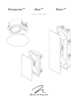
user’s manual
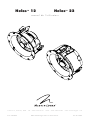
Helos™ 12 Helos™ 22
Lawrence, Kansas, USA tel 785.749.0133 fax 785.749.5320 www.martinlogan.com
Rev. #112612©2012 MartinLogan Ltd. All rights reserved.
®
P.N. 9500089

2
WARNING!
• Refer servicing to a qualified
technician.
• To prevent fire or shock hazard,
do not expose this module to moisture.
• Turn amplifier off should any abnormal
conditions occur.
• Do not drive speaker beyond its rated power.
Content Check List ....................... 3
Connection ............................ 4
Protect Your Investment .................. 4
Break-In ............................5
Speaker Placement ....................5
Achieving Superior Imaging ............5
Balancing Hard vs. Soft Surfaces Improves
High- and Mid-Frequency Performance .....5
Choosing a Mounting Location ..........5
Balancing Bass Output................5
Helos 12 Placement ....................5
Helos 22 Placement ....................6
Painting the Speaker Grill ................. 8
Installation ............................. 8
Frequently Asked Questions .............. 10
Troubleshooting ....................... 10
Contacting Customer Service ............10
General Information .................... 11
Warranty Information ................11
Serial Number .....................11
Service .........................11
Specifications ......................... 12
Serial Number:_____________________________
Record your serial number here for easy reference.
You will need this information when filling out your
warranty registration. The serial number is located
near the binding posts and on the product carton.
In accordance with the European Union
WEEE (Waste Electrical and Electronic
Equipment) directive effective August 13,
2005, we would like to notify you that this prod-
uct may contain regulated materials which upon
disposal, according to the WEEE directive, require
special reuse and recycling processing. For this rea-
son Martin Logan has arranged with our distributors
in European Union member nations to collect and
recycle this product at no cost to you.
To find your local distributor please contact the
dealer from whom you purchased this product,
email [email protected] or visit the distributor
locator at www.martinlogan.com.
Please note, only this product itself falls under
the WEEE directive. When disposing of pack-
aging and other related shipping materials we
encourage you to recycle these items through the
normal channels.
The lightning bolt flash with arrowhead
symbol within an equilateral triangle
is intended to alert the user to the presence
of uninsulated “dangerous voltage” within the
product’s enclosure that may be of sufficient
magnitude to constitute a risk of electric shock.
The exclamation point within an equilat-
eral triangle is intended to alert the user
to the presence of important operating and
maintenance (servicing) instructions in the litera-
ture accompanying the appliance.
The fire within an equilateral triangle is
intended to alert the user to the potential
of creating a fire hazard if they do not follow
the instructions.
The dollar sign within an equilateral tri-
angle is intended to alert the user that
they run the risk of causing damage that could
be potentially expensive to repair if they don’t
follow the instructions.

3
Helos 12 Helos 22
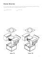
Content CheCk List
You will find the following items enclosed for your new MartinLogan loudspeaker. Should you require
assistance please call our service department at (785) 749-0133.
______ Install Template ______ Grill Cover

4
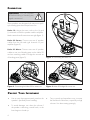
ConneCtion
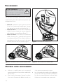
WARNING! Turn your amplifier
off before making or breaking any
signal connections!
These speakers are designed with easy-to-use push-
style binding posts that accept bare wire.
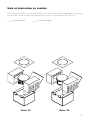
Helos 12: Assign the same color to the (+) and
(–) terminals on both the speaker and the amplifier.
Make certain that all connections are tight (figure 1).
Helos 22 Stereo: Connect two sets of speaker
cables from the left and right channels of your
amplifier (figure 2).
Helos 22 Mono: Connect one sets of speaker
cables to one set of binding posts on the Helos 22
and use matching cable to bridge the second set
of binding posts (figure 3).
• Use an amp that approximately matches the
speaker’s specified power handling.
• To avoid damage, turn down the volume if
the speaker is distorting, sounds harsh, or the
bass begins to break up.
• Tone controls and equalizers may increase
the likelihood of distortion, especially at high
volumes. Use these setting sparingly.
ProteCt Your investment
Figure 3. Helos 22 bridged for mono use.Figure 2. Connecting the Helos 22 for stereo use.
Figure 1. Connecting the Helos 12.

5
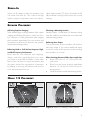
When you first begin to play your speakers, they
will sound a bit bass shy. This is due to the high
quality, long-life components used in the drivers.
Allow approximately 72 hours of break-in at 90
dB (moderate listening levels) before any critical
listening.
Break-in
sPeaker PLaCement
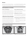
Achieving Superior Imaging
These MartinLogan in-ceiling speakers offer superb
imaging and flexible placement in nearly any loca-
tion. However, for best performance and imaging
place speakers equidistant from one another and
avoid physical obstructions between the speaker
and primary listening position.
Balancing Hard vs. Soft Surfaces Improves High-
and Mid-Frequency Performance
Rooms that are “over damped” with carpeting,
drapes, and other sound absorbers can cause
your system to sound dull and lifeless. On the other
hand, rooms can have so many hard surfaces that
the system sounds like a gymnasium. Experiment
by adding or removing soft surfaces until you find
a mix that sounds good to you.
Choosing a Mounting Location
Install the Helos 12 and Helos 22 between ceiling
joists. Be careful to avoid electrical wires behind the
wall and ceiling surfaces.
Balancing Bass Output
Corner placement of these speakers will reinforce
their bass output. If you require balanced output
across the entire audio spectrum avoid mounting
these speakers in a corner.
When choosing placement follow these simple tips:
• Place a minimum of 12” (30cm) from any
wall corner.
• Place front and center channels equidistant
between 10–14 feet (3–4.3m) from the lis-
tening position.
•
Orient the tweeter towards the listening position.
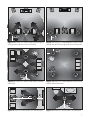
Figure 5. Helos 12: Adding a center channel.Figure 4. Helos 12: 2-channel installation.
heLos 12 PLaCement

6
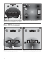
Figure 8. Helos 22: Stereo mode reproducing both
the left and right surround channels.
Figure 9. Helos 22: Wide dispersion. Mono mode
reproducing the rear center surround channel.
Figure 7. Helos 12: Distributed audio.Figure 6. Helos 12: Adding surround channels to
create a 5- or 7-channel installation.
heLos 22 PLaCement

7
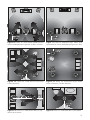
Figure 14. Helos 22: Stereo mode in a 2-channel system.
Figure 15. Helos 22: Stereo mode in a small space.
Figure 10. Helos 22: Stereo mode reproducing left
and right side and rear surround channels.
Figure 11. Helos 22: Wide dispersion. Mono mode
reproducing the left and right side surround channels.
Figure 12. Helos 22: Stereo mode used for distrib-
uted audio.
Figure 13. Helos 22: Wide dispersion. Mono mode
used for distributed audio.

8
IMPORTANT! Before painting remove grill from
speakers. Also remove the cloth scrim attached
inside the grill.
1. Remove the grill from the speaker. A protec-
tive cloth scrim is attached to the back of
the grill with low-tack adhesive. Remove this
scrim by gently pulling it away from the grill.
2. Paint the grill, being careful not to plug the
holes. Allow the paint to completely dry before
proceeding. IMPORTANT! For best results
use a spray rather than a brush or roller.
3. Gently press the scrim back into place before
reinstalling the speaker grill.
Painting the sPeaker griLL
NOTE: These instructions assume the mounting sur-
face is of standard wood frame and standard sheet
rock construction. If you wish to mount the speakers
to another type of material you should contact a
bonded contractor.
NOTE: See your local dealer for new construction
pre-install brackets (sold separately).
WARNING! Before installing check
local building codes to verify compli-
ance with local regulations WARN-
ING! Before installing check for
obstructions behind drywall. To do
this make a small hole, cutting at a
45° angle (this will make the hole
easier to patch if obstructions are
found. Only cut out the mounting
hole after you have verified there are
no obstructions behind the dry wall.
WARNING! Use only speaker cable
that is rated for in-wall use. The UL
standard is CL2, CL3, and CM. The
CSA standard is FT4. WARNING!
Turn your amplifier off before making
or breaking any signal connections.
Recommended tools:
• Stud finder
• Sharp pencil or pen
• Pushpin
• Dry wall knife/saw
• Wire strippers
• Phillips screwdriver or electric drill and bit
• Tape measure
• Low-tack tape
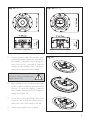
1. Using a stud finder, position the template
completely between ceiling joists.
2. Hold or pin the template in place and mark
cutout with a pencil.
3. Remove the template and cut out the opening
with a drywall knife/saw.
4. Place fiberglass insulation 12” (30cm) or thicker
between the joists directly above the speaker.
instaLLation
Fig. 16

9
5 Connect speaker cable. Be consistent when
connecting speaker leads to the terminals on
the speaker. Take great care to assign the
same color to the (+) terminal on both the
speaker and the amplifier. See “Connection”
section of this manual for further details.
WARNING! Turn your amplifier
off before making or breaking any
signal connections!
6 Place speaker in hole. Gently pivot the tweet-
er stem to point towards the primary listening
position. To rotate the speaker, rotate the
entire speaker assembly. DO NOT rotate the
tweeter stem (figure 19).
7 Use a 2-inch long #2 Phillips driver and
an electric drill to lock all mounting locks in
place. Use a low clutch setting on the drill.
8 Gently press the grill cover into place.
Fig. 17 Helos 12 Fig. 18 Helos 22
Fig. 19

10
How do I clean my speakers? Just use a dust free
cloth or a soft brush to remove the dust from your
speakers. Do not spray any kind of cleaning agent
on or in close proximity to the drivers.
What size amplifier should I use? We rec-
ommend an amplifier rated within the suitable
amplifier range of your speaker.
Could you suggest a list of suitable electronics
and cables that would be ideal for MartinLogan
speakers? The area of electronics and cable
choice is probably the most common type of
question that we receive. It is also the most
subjective. We have repeatedly found that brands
that work well in one setup will drive someone else
nuts in another. We use many brands with great
success. Again, we have no favorites; we use
electronics and cables quite interchangeably. We
would suggest listening to a number of brands—
and above all else—trust your ears. Dealers are
always the best source for information when
purchasing additional audio equipment or cables
and will be well versed in the subject of special
safety requirements for in-wall cable.
Will exposure to sunlight affect the life or
performance of my speakers? We recommend
that you not place any loudspeaker in direct
sunlight. The ultraviolet (UV) rays from the sun can
cause deterioration of grill cloth, speaker cones, etc.
Small exposures to UV will not cause a problem. In
general, the filtering of UV rays through glass will
greatly reduce the negative effects.
FrequentLY asked questions
No Output
• Check that all your system components are
turned on, not muted, and that your balance
control (if applicable) is set correctly.
• Check to make sure your power outlet at the
wall is working.
• Check your power cords, speaker wires, and
interconnecting cables.
• Check to make sure no headphones are
plugged in.
• Swap speaker wires at your amplifier with
those of a speaker that is functioning correct-
ly. If the lack of output moves to a different
speaker the problem could be with other
equipment in your system (i.e. amp, pre-amp,
processor, etc.)
• Try hooking up a different set of speakers.
The lack of output could point to a problem
with other equipment in your system (i.e.
amp, pre-amp, processor, etc.)
Lack of Bass or Poor Imaging
• Check your speaker wires. Is the polarity cor-
rect — (+) to (+) and (–) to (–).
trouBLeshooting
MartinLogan customer service is available
Monday–Friday between the hours of 8am–5pm
(central time) by calling (785) 749-0133 or by
emailing [email protected].
ContaCting Customer serviCe

11
WARRANTY INFORMATION
Your speakers are provided with an automatic
Limited 90 Day Warranty coverage. You have
the option, at no additional charge, to receive a
Limited 5 Year Warranty coverage. To obtain the
Limited 5 Year Warranty coverage you need to
complete and return the Certificate of Registration
to MartinLogan within 30 days of purchase. For
your convenience MartinLogan also offers online
warranty registration at www.martinlogan.com.
MartinLogan may not honor warranty service
claims unless we have a completed Warranty
Registration card on file! If you did not receive a
Certificate of Registration with your new speakers
you cannot be assured of having received new
units. If this is the case, please contact your autho-
rized MartinLogan dealer.
SERIAL NUMBER
Serial number is located on back of the speaker,.
The serial number may also be found on the prod-
uct carton.
SERVICE
Should you use your MartinLogan product in a
country other than the one in which it was originally
purchased, we ask that you note the following:
1 The appointed MartinLogan distributor for any
given country is responsible for warranty servicing
only on units distributed by or through it in that coun-
try in accordance with its applicable warranty.
2 Should a MartinLogan product require ser-
vicing in a country other than the one in which
it was originally purchased, the end user may
seek to have repairs performed by the nearest
MartinLogan distributor, subject to that distribu-
tor’s local servicing policies, but all cost of repairs
(parts, labor, transportation) must be borne by the
owner of the MartinLogan product.
3 If, after owning your speaker for six months, you
relocate to a country other than the one in which
you purchased your speaker, your warranty may be
transferable. Contact MartinLogan for details.
generaL inFormation

12
*Specifications are subject to change without notice.
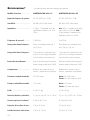
sPeCiFiCations*
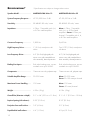
Speaker Model.............
System Frequency Response ..
Sensitivity................
Impedance ...............
Crossover Frequency........
High-Frequency Driver .......
Low-Frequency Driver........
Binding Post Inputs..........
Components...............
Suitable Amplifier Range .....
Maximum Power Handling ...
Weight..................
Overall Size (diameter x depth) .
Required opening (with tolerance)
..
Projection from wall surface ...
Depth behind wall surface ....
MARTINLOGAN Helos 12
47–20,000 Hz ± 3 dB
89 dB @ 2.83 volts/ meter
4 Ohms. Compatible with 4, 6,
or 8 Ohm rated amplifiers.
2,800 Hz
1” (2.5cm) neodymium soft
dome
6.5” (16.5cm) high-rigidity alu-
minum cone with extended throw
drive assembly, thermal protection.
Push style binding posts, accom-
modates wire up to 5AWG.
Custom air core coils, polyester caps
20–200 watts
100 watts
4.5 lbs. (2 kg)
9.1” x 4.6” (23.1cm x 11.8cm)
8.35” (21.2cm)
0.2” (4.5mm)
4.4” (11.2cm)
MARTINLOGAN Helos 22
47–20,000 Hz ± 3 dB
89 dB @ 2.83 volts/ meter
Mono: 4 Ohms. Compatible
with 4, 6, or 8 Ohm rated
amplifiers. Stereo: 8 Ohms per-
channel. Compatible with 4, 6,
or 8 Ohm rated amplifiers.
2,600 Hz
Two 0.78” (1.9cm) neodymium
soft dome
6.5” (16.5cm) high-rigidity alu-
minum cone with extended throw
drive assembly, thermal protection.
Push style binding posts, accom-
modates wire up to 5AWG.
Custom air core coils, polyester caps
Mono: 20–200 watts
Stereo: 20–100 watts per channel
Mono: 100 watts
Stereo: 50 watts/channel
4.5 lbs. (2 kg)
9.1” x 5.1” (23.1cm x 12.8cm)
8.35” (21.2cm)
0.2” (4.5mm)
4.9 po (12.3 cm)

manuel de l’utilisateur
Helos™ 12 Helos™ 22
Lawrence, Kansas, USA tél. 785.749.0133 téléc. 785.749.5320 www.martinlogan.com
Rev. #112612©2012 MartinLogan Ltd. Tous droits réservés.
®
P.N. 9500089

14
Liste de vérification du contenu ...........15
Raccordement........................16
Protéger votre investissement ............16
Rodage ............................17
Positionnement des enceintes ............17
Obtenir une image supérieure ..........17
L’équilibre entre les surfaces dures et molles
améliore le rendement des hautes et des
moyennes fréquences ..............17
Choisir un emplacement de montage .....17
Équilibrage de la sortie des graves.......17
Helos 12 Positionnement ...............17
Helos 22 Positionnement ...............18
Peinturer la grille de l’enceinte ...........20
Installation ..........................20
Foire aux questions ...................22
Dépannage .........................22
Communiquer Avec le Service à la Clientèle..23
Renseignements Généraux ..............23
Renseignements sur la garantie .........23
Numéro de série...................23
Service .........................23
Spécifications ........................24
Numéro de Série :__________________________
Veuillez inscrire votre numéro de série ici pour pouvoir
vous y référer facilement. Vous aurez besoin de ce ren-
seignement lorsque vous remplirez votre enregistrement
à la garantie. Le numéro de série est situé près des
bornes de raccordement et sur l’emballage du produit.
En vertu de la directive WEEE de l’Union euro-
péenne (directive sur les déchets électriques
et électroniques) entrée en vigueur le 13 août
2005, nous vous avisons que ce produit pourrait contenir
des matériaux réglementés dont l’élimination doit faire l’objet
de procédures de réutilisation et de recyclage particulières.
À cette fin, MartinLogan a demandé à ses distributeurs dans
les pays membres de l’Union européenne de reprendre et
de recycler ce produit gratuitement.
Pour trouver le distributeur le plus près, communiquez avec le
revendeur du produit, envoyez un courriel à info@martinlo-
gan.com ou consultez le site Web martinlogan.com.
Notez que seul le produit est régi par la directive
WEEE. Nous vous encourageons à recycler les matéri-
aux d’emballage et autres matériaux d’expédition selon
les procédures normales.
AVERTISSEMENT!
• Pour les réparations, faites appel à
un technicien compétent.
• Pour éviter les risques d’incendie
ou de décharge électrique, n’exposez pas ce
module aux vapeurs d’eau ni à l’humidité.
• Veuillez éteindre l’amplificateur en cas de
conditions anormales.
• Ne poussez pas l’enceinte au-delà de sa puis-
sance nominale.
Le symbole de l’éclair avec une pointe en forme
de flèche, dans un triangle équilatéral, avertit
l’utilisateur de la présence d’une « tension dangereuse
» potentielle près du produit qui peut être suffisante pour
constituer un risque de décharge électrique.
Le point d’exclamation dans un triangle équi-
latéral avertit l’utilisateur de la présence de
directives importantes en matière de fonctionnement
et d’entretien (service) dans les documents qui accom-
pagnent l’appareil.
Le symbole de feu dans un triangle équilaté-
ral avertit l’utilisateur du risque de créer un
incendie s’il ne suit pas les instructions.
Le symbole de dollar dans un triangle équila-
téral avertit l’utilisateur qu’il coure le risque de
causer des dommages potentiellement dispendieux à
réparer s’il ne suit pas les instructions.

15
Helos 12 Helos 22
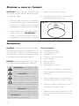
______ Gabarit d'installation ______ Couvercle de la grille
Liste de vériFiCation du Contenu
Vous trouverez les éléments suivants dans la boîte pour votre nouvelle enceinte MartinLogan. Si vous avez
besoin d’aide, veuillez appeler notre département de service en composante le 785-749-0133.

16
raCCordement
• Utilisez un amplificateur qui correspond
approximativement à la puissance admissible
de l’enceinte.
• Pour éviter les dommages, baissez le volume
si le son de l’enceinte est déformé ou dur, ou
si les graves commencent à couper.
• Les commandes de tonalité et les égalisateurs
peuvent accroître les possibilités de déforma-
tion du son, particulièrement à volume élevé.
Utilisez ces commandes avec parcimonie.
Protéger votre investissement
AVERTISSEMENT! Éteignez
l’amplificateur avant de faire des
raccordements ou d’interrompre
tout raccordement de signal!
Ces enceintes sont dotées de bornes de raccorde-
ment facile à utiliser de style bouton-poussoir qui
acceptent les fils nus.
•
Helos 12 : Attribuez la même couleur aux bornes
(+) et (-) sur l’enceinte et l’amplificateur. Assurez-
vous que tous les raccords sont bien faits (fig. 1).
• Helos 22 Stéréo : raccordez deux ensembles de
câbles d’enceinte à partir des canaux de gauche
et de droite de votre amplificateur (figure 2).
• Helos 22 Mono : raccordez un ensemble de
câbles d’enceinte à un ensemble de bornes de
raccordement du Helos 22 et utilisez le câble cor-
respondant pour faire le pont avec le deuxième
ensemble de bornes de raccordement (figure 3).
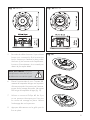
Figure 3. Helos 22 ponté pour une utilisation en mono.Figure 2. Raccordement du Helos 22 pour une utilisation en stéréo.
Figure 1. Raccordement du Helos 12.

17
Quand vous commencez à l’utilisez les enceintes, les
graves peuvent sonner un peu diminuées. Cette situa-
tion est due aux composants de haute qualité et à durée
de vie élevée utilisés dans les haut-parleurs. Un rodage
d’environ 72 heures à 90 dB (niveaux d’écoute moy-
ens) est nécessaire avant toute écoute critique.
rodage
Positionnement des enCeintes
Obtenir une image supérieure
Ces enceintes MartinLogan encastrables au
plafond offrent une superbe image et un posi-
tionnement flexible presque partout. Toutefois, pour
obtenir le meilleur rendement possible et la meil-
leure image, placez les enceintes à équidistance
les unes des autres et éviter les obstacles physiques
entre l’enceinte et la position d’écoute principale.
L’équilibre entre les surfaces dures et molles améliore
le rendement des hautes et des moyennes fréquences
Les pièces qui sont « trop amorties » avec du tapis,
des rideaux ou d’autres matériaux qui absorbent le
son peuvent faire en sorte que votre système sonne
mat ou sans vie. D’un autre côté, les pièces peuvent
avoir tellement de surfaces dures que le système son-
nera comme dans un gymnase. Expérimentez en
ajoutant ou en enlevant des surfaces molles jusqu’à
ce que vous trouviez un mélange qui sonne bien.
Choisir un emplacement de montage
Installez Helos 12 et Helos 22 entre les solives du
plafond. Faites attention d’éviter les fils électriques
derrière les murs et sous le plafond.
Équilibrage de la sortie des graves
Le positionnement en coin de ces enceintes ren-
forcera la sortie des graves. Si vous avez besoin
d’une sortie équilibrée dans l’ensemble du spectre
audio, évitez de monter ces enceintes dans un coin.
Conseils pratiques pour le choix du positionnement :
• Laissez un espace minimal de 12 po (30cm)
de tout coin de mur.
• Placez les enceintes avant/centre à équidis-
tance de 10 à 14 pieds (3 à 4,3 m) de la
position d’écoute.
• Orientez le son vers la position d’écoute.
Figure 5. Helos 12: Ajouter un canal central.Figure 4. Helos 12: Installation à 2 canaux.
heLos 12 Positionnement

18
Figure 8. Helos 22: mode stéréo reproduisant les
canaux ambiophoniques gauche et droit.
Figure 9. Helos 22: dispersion large. Mode mono
reproduisant le canal ambiophonique arrière central.
Figure 7. Helos 12: Stéréo audio distribué.
Figure 6. Helos 12: Ajouter des canaux ambiopho-
niques pour créer une installation à 5 ou 7 canaux.
heLos 22 Positionnement

19
Figure 14. Helos 22: mode stéréo dans un sys-
tème à deux canaux.
Figure 15. Helos 22: mode stéréo dans un petit espace.
Figure 10. Helos 22: mode stéréo reproduisant les
canaux ambiophoniques gauche et droit, et arrière .
Figure 11. Helos 22: dispersion large. Mode mono
reproduisant les canaux ambiophoniques gauche et droit.
Figure 12. Helos 22: mode stéréo utilisé pour
l’audio distribué.
Figure 13. Helos 22: dispersion large. Mode
mono utilisé pour l’audio distribué.

20
IMPORTANT! Avant de peinturer, enlevez la grille
des enceintes. De plus, enlevez le disque de tissu fixé
à l’intérieur de la grille.
1. Enlevez la grille de l’enceinte. Un disque de
tissu protecteur est fixé sur la partie arrière de
la grille avec un adhésif. Retirez ce disque
de grillage en tirant délicatement sur la grille.
2. Peignez la grille, en faisant attention de ne
pas boucher les trous. IMPORTANT! Pour
obtenir de meilleurs résultats, utilisez un
vaporisateur au lieu d’un pinceau. Laissez la
peinture sécher avant de continuer.
3. Fixez doucement le disque à sa place avant
de réinstaller la grille de l’enceinte.
Peinturer La griLLe de L’enCeinte
REMARQUE : ces instructions supposent que la surface
de montage est un cadre en bois standard et une con-
struction en gyproc standard. Si vous souhaitez monter
les enceintes sur un autre type de matériel, vous devez
communiquer avec un entrepreneur cautionné.
REMARQUE : consultez votre revendeur local pour obtenir
les nouveaux supports préinstallés (vendus séparément).
AVERTISSEMENT! Avant l’installation, vérifiez
les codes de construction locaux pour vous
assurer de la conformité aux règlements
locaux. AVERTISSEMENT! Avant l’installation,
vérifiez la présence d’obstacles derrière la
cloison sèche. Pour y arriver, percez un petit
trou, à un angle de 45° (il sera insi plus
facile de reboucher le trou si des obstacles
sont repérés). Découpez le trou de montage uniquement
lorsque vous avez vérifié qu’il n’y a aucun obstacle derrière
la cloison sèche. AVERTISSEMENT! Utilisez uniquement
un câble d’enceinte homologué pour l’utilisation dans un
mur. La norme UL est CL2, CL3 et CM. La norme CSA est
FT4. AVERTISSEMENT! Éteignez l’amplificateur avant de
faire ou de défaire tout raccord de signal.
Outils recommandés :
• Localisateur de montants
• Crayon aiguisé ou stylo
• Goupille-poussoir
• Couteau/scie à cloison sèche
• Pince à dénuder
• Tournevis Phillips
• Ruban à mesurer
• Ruban adhésif « low-tack »
1. À l’aide d’un localisateur de montants,
placez le gabarit entièrement entre les solives
du plafond.
2. Tenez le gabarit en place ou accrochez-le et
marquez la forme découpée avec un crayon.
3. Enlevez le gabarit et découper le trou à
l’aide d’une scie à cloison sèche.
4. Placez un isolant en fibre de verre de 12 po (30
cm) ou plus entre les solives directement sous
l’enceinte.
instaLLation
Fig. 16
La page est en cours de chargement...
La page est en cours de chargement...
La page est en cours de chargement...
La page est en cours de chargement...
-
 1
1
-
 2
2
-
 3
3
-
 4
4
-
 5
5
-
 6
6
-
 7
7
-
 8
8
-
 9
9
-
 10
10
-
 11
11
-
 12
12
-
 13
13
-
 14
14
-
 15
15
-
 16
16
-
 17
17
-
 18
18
-
 19
19
-
 20
20
-
 21
21
-
 22
22
-
 23
23
-
 24
24


dans d''autres langues
- English: MartinLogan Helos 22 User manual
Documents connexes
-
Motorola Solutions ML-55 Manuel utilisateur
-
MartinLogan Sistine 4XC Manuel utilisateur
-
 MartinLogan ML-65AW Le manuel du propriétaire
-
 MartinLogan ML-65 Manuel utilisateur
-
 MartinLogan Axis Manuel utilisateur
-
MartinLogan Icon 3XW Manuel utilisateur
-
MartinLogan Motion XTC8 Manuel utilisateur
-
 MartinLogan ElectroMotion IC Manuel utilisateur
-
 MartinLogan ML-65 Manuel utilisateur
-
MartinLogan IC6-HT Manuel utilisateur


