
DANFOSS HEATING SOLUTIONS
MAKING MODERN LIVING POSSIBLE
Installation Guide
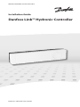
Danfoss Link™ Hydronic Controller


Danfoss Heating Solutions VIFZL55X 2019.09
3
NL
Installation Guide Danfoss Link™ HC
Installation guide ...................................... 5
Installationsanleitung.................................12
Installationsvejledning................................20
Guide d’installation ...................................28
Installatiehandleiding.................................36
Asennusopas .........................................44
Instalační příručka ....................................52
Instrukcja montażu ...................................60
EN
DE
DK
FR
FI
CZ
PL

4
2019.09 VIFZL55X Danfoss Heating Solutions
Installation Guide Danfoss Link™ HC

Danfoss Heating Solutions VIFZL55X 2019.09
5
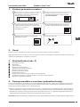
Content
1. Quick guide for Installation .........................................................6
2. Introduction .......................................................................6
3. Functional Overview (fig. 2).........................................................4
4. Mounting and Installation Procedure (Sequential)....................................6
4.1 Danfoss Link™ HC ....................................................................7
4.2 24 V Actuators .......................................................................7
4.3 Relays for Pump and Boiler Control ...................................................7
4.4 Input for Away Function ..............................................................7
4.5 Input for Heating and Cooling ........................................................7
4.6 Wiring ...............................................................................7
4.7 Power Supply ........................................................................7
4.8 CF-EA External Antenna ..............................................................8
5. Configuration......................................................................8
5.1 Adding Danfoss Link™ HC to the system...............................................8
5.2 Configuring Danfoss Link™ HC........................................................8
5.3 Creating rooms ......................................................................9
5.4 Adding an output to a room ..........................................................9
5.5 Configuring a room .................................................................10
5.6 Performing a network test after adding new devices .................................10
5.7 Leaving the service area in Danfoss Link™ CC.........................................10
6. Maintenance..................................................................... 10
6.1 Removing an output ................................................................10
6.2 Factory reset . . . . . . . . . . . . . . . . . . . . . . . . . . . . . . . . . . . . . . . . . . . . . . . . . . . . . . . . . . . . . . . . . . . . . . . .11
7. Technical Specifications .......................................................... 11
8. Troubleshooting ................................................................. 11
Figures and Illustrations...........................................................A1 & A2
SIMPLIFIED EU DECLARATION OF CONFORMITY
Hereby, Danfoss A/S declares that the radio equipment type Danfoss Link™ HC are in compliance
with Directive 2014/53/EU.
The full text of the EU declaration of conformity is available at the following internet address:
heating.danfoss.com
Installation Guide Danfoss Link™ HC
EN

6
2019.09 VIFZL55X Danfoss Heating Solutions
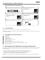
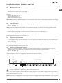
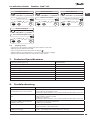
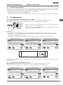
1. Quick guide for Installation
21
3
4
5
6
2. Introduction
Danfoss Link™ is a wireless control system for a variety of heating systems.
The Danfoss Link™ HC is a part of this system allowing wireless control of manifolds for water based
floor heating/cooling.
3. Functional Overview (fig. 2)
Output LEDs.
Boiler relay.
Pump relay.
Actuator connections.
Install/Link Test.
External antenna connection.
Front cover release.
Not in use (Input 1).
Away Function (Input 2) (external ON/OFF switch).
Input for heating/cooling (Input 3) (external ON/OFF switch).
Output cable fixing.
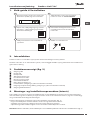
4. Mounting and Installation Procedure (Sequential)
The wireless systems transmission range is sufficient for most applications; however, wireless signals
are weakened on the way from the Danfoss Link™ to the Room Thermostats and each building has
different obstacles.
Checklist for optimal installation and best wireless signal strength (fig. 1):
• No metal objects between the Danfoss Link™ HC and the Room Thermostats.
• Wireless signal through walls on shortest possible diagonal distance.
• Optimise the wireless signal by installing a RU Repeater Unit.
Note! Danfoss recommends that an installation plan is made before beginning the actual installation (fig. 1).
Mount the Danfoss Link™ HC, connect
all actuators (TWA) and power-up the
unit
Add Danfoss Link™ HC to the
Danfoss Link™ CC as a
service device
Create rooms, add outputs and Room
Thermostats - choose
output type in actuator
settings
Perform a network test
Check the configuration in
Danfoss Link™ HC
setting menu
Add any other devices to the system
Installation Guide Danfoss Link™ HC

Danfoss Heating Solutions VIFZL55X 2019.09
7
Installation Guide Danfoss Link™ HC
4.1 Danfoss Link™ HC
Mount the Danfoss Link™ HC in an horizontal upright position.
Wall:
• Remove the front and side covers (fig. 3).
• Mount with screws and wall plugs (fig. 3).
DIN-Rail:
• Mount DIN-rail parts (fig. 4).
• Click on DIN-rail (fig. 5).
• Release from DIN-rail (fig. 6).
Important! Complete all the installations on the Danfoss Link™ HC as described below, before connecting
to a 230 V power supply!
4.2 24 V Actuators
• Connect the two actuator wires to an output (fig. 7).
• Fix the cable (fig. 8).
Note! If NC (normally closed) actuators are installed for ON/OFF regulation, no further actuator output
configuration is needed.
4.3 Relays for Pump and Boiler Control
• Connect wires for pump and boiler controls to their respective output (fig. 9).
• Fix the cable (fig. 10).
Note! The relays for pump and boiler are potential free contacts and can therefore NOT be used as direct
power supply. Max. load is 230 V and 8 A/2 A!
4.4 Input for Away Function
• Connect an external ON/OFF switch to the terminals for Away Function (Input 2). When this switch
is closed (ON) the system will override all room thermostat set points and change the temperature
to 15 °C (fig. 11).
• Fix the cable (fig. 12).
Note! The Away Function ensures a set room temperature fixed at 15 °C for all room thermostats, but it
can be changed with the Danfoss Link™ CC.
4.5 Input for Heating and Cooling
• Connect an external ON/OFF switch to the terminals for Heating and Cooling (Input 3) (fig. 13).
With the switch closed (ON), the system will switch from heating to cooling mode.
• Fix the cable (fig. 14).
Note! With the system in cooling mode, the actuator output will be activated (ON for NC actuators/OFF
for NO actuators), when the temperature in a room exceeds the set point.
When the system is in cooling mode a dew-point sensor should be installed.
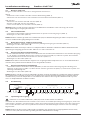
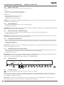
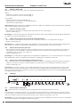
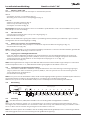
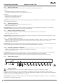
4.6 Wiring
L
N
L
N
910876 54321
Input Relays Actuator outputs
Ex
ternal
antenna
Input 1
Input 2
Input 3
Max. 3 m
4.7 Power Supply
Connect all actuators (TWA), before mains powering the unit!
Then, connect the Danfoss Link™ HC power supply plug to a 230 V power supply, when all actuators,
pump and boiler controls and other inputs are installed. The Danfoss Link™ HC is now ready to be
added to the Danfoss Link™ CC.
Note! If the power supply plug is removed from the power supply cable during installation, ensure that the
connection is made according to existing law/legislation.
EN

8
2019.09 VIFZL55X Danfoss Heating Solutions
Installation Guide Danfoss Link™ HC
4.8 CF-EA External Antenna
The CF-EA is installed as diverter when there is no transmission possible through a large building,
heavy construction or metal barrier, e.g. if the Danfoss Link™ HC is located in a metal cabinet/box.
• Remove the plastic cover from the antenna connection on the Danfoss Link™ HC (fig. 15).
• Connect the CF-EA (fig. 16).
• Place the CF-EA on the other side of the transmission barrier away from the Danfoss Link™ HC.
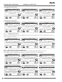
5. Configuration
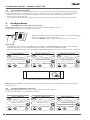
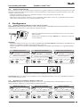
5.1 Adding Danfoss Link™ HC to the system
Note! Adding Danfoss Link™ HC to a system is made from the Danfoss Link™ CC.
For further information, see separate instruction.
• Remove the front cover of the Danfoss Link™ CC by gently pulling
it off, pull near the edges of the cover.
• Press the SETUP pin for 3 seconds to enter the service area.
Important!
• The Danfoss Link™ HC must be added to the network as a service device. For further instructions on
network inclusion, see more information in the Danfoss Link™ CC Installation Guide.
• Add any dedicated repeater units (CF-RU) BEFORE adding the Danfoss Link™ HC to the wireless network.
?
1
Service Options
Rooms and Devices
?
2
Rooms and Devices
Add Service Device
?
3
Add Service Device
Begin Registration
Click here for adding the Danfoss Link™ HC
Note! During installation, the distance between the Danfoss Link™ CC and the Danfoss Link™ HC must
not exceed 1.5m.
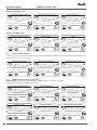
5.2 Configuring Danfoss Link™ HC
Note! Configuring Danfoss Link™ HC is made from the Danfoss Link™ CC.
For further information, see separate instruction.
?
1
Service Options
Rooms and Devices
?
2
Rooms and Devices
Manage Devices
?
3
Manage Devices
Configure Device

Danfoss Heating Solutions VIFZL55X 2019.09
9
Installation Guide Danfoss Link™ HC
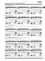
Configuring outputs
?
1
Setup
Configure Device
?
2
Setup Relays
Configure Device
?
3
Choose settings
Setup Relays
Configuring inputs
?
1
Configure Device
Setup Inputs
?
2
Setup Inputs
Select Input
?
3
Input
Choose setting
5.3 Creating rooms
Danfoss recommends to create and add device(s) to one room in a single step, and there-after move
on to the next room.
?
1
Service Options
Rooms and Devices
?
2
Rooms and Devices
Add New Room
?
3
Edit Room Name
Enter/Edit Room Name
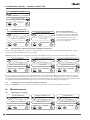
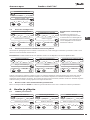
5.4 Adding an output to a room
Note! Configuring Danfoss Link™ HC is made from the Danfoss Link™ CC.
For further information, see separate instruction.
?
1
Configure Room
Rooms Devices
?
2
Rooms Devices
Add a Device
?
3
Room Devices
Use an Output
?
4
Select Device
Select
?
5
Select Output
Select from list
?
6
Select Heating Emitter
Actuator Setting
EN

10
2019.09 VIFZL55X Danfoss Heating Solutions
Installation Guide Danfoss Link™ HC
?
7
Actuator Settings
Select type / OK
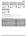
5.5 Configuring a room
?
1
Configure Room
Heating regulation
?
2
Heating Regulation
Select type
Forecasting method:
By activation of the forecast
method, the system will auto-
matically predict the heating
start-up time necessary to
reach desired room tempera-
ture at desired time.
5.6 Performing a network test after adding new devices
After finishing installation, perform a network test to ensure that communication between added
devices and the Danfoss Link CC™ is stable.
Note! Do not perform the network test before the Danfoss Link™ CC is mounted in its final position.
?
1
Service Options
Status and Diagnostics
?
2
Status and Diagnostics
Network
?
3
Wireless Network Status
Start Network Test
At the end of the network test the Danfoss Link™ CC awaits for all battery operated devices to wake
up and report. Follow the instructions given on the screen. If the network test is running smoothly,
there will be no need for further interaction. If the network test is performing slow, the Danfoss Link™
CC guides through troubleshooting and gives useful tips for speeding up the process.
5.7 Leaving the service area in Danfoss Link™ CC
Press the SETUP pin for 3 seconds and put back the front cover to the Danfoss Link™ CC.
6. Maintenance
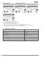
6.1 Removing an output
?
1
Service Options
Rooms and Devices
?
2
Rooms and Devices
Manage Devices
?
3
Select Room
Select existing room

Danfoss Heating Solutions VIFZL55X 2019.09
11
Installation Guide Danfoss Link™ HC
?
4
Configure Room
Room Devices
?
5
Room Devices
Remove a device
?
6
Room Devices
Remove an Output
?
7
Remove Output
Yes, remove output now
6.2 Factory reset
• Disconnect the power supply for the Danfoss Link™ HC.
• Wait for green LED to turn off.
• Press and hold the Install/Link Test (fig. 2 ).
• While holding Install/Link Test, reconnect the power supply.
• Release the Install/Link Test, when the LEDs are on.
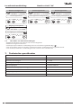
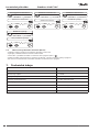
7. Technical Specifications
Transmission frequency 868.42 MHz
Transmission range in normal constructions up to 30 m
Transmission power < 1 mW
Supply voltage 230 V AC
Actuator outputs 5 or 10 x 24 V DC
Max. continued output load (total) 25 VA
Relays 230 V AC/8 (2) A
Ambient temperature 0 - 50 °C
IP class 30
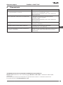
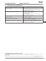
8. Troubleshooting
Error Indication Possible Causes
Impossible to add devices to
the Danfoss Link™ CC system
The distance between the Danfoss Link™ CC and the Danfoss
Link™ HC has exceeded 1.5m.
For further information, see instruction for the Danfoss Link™ CC.
The connection to a device is
lost
- Empty/low battery
- The wireless signal is weak
- Defective device
For further information, see instruction for the Danfoss Link™ CC.
Actuator (TWA) not visible on
Danfoss Link™ CC
- Actuator incorrectly mounted
- Defective actutator
Flashing output/alarm LEDs - Output or actuator is short-circuited
- The actuator is disconnected
High room temperature (above
comfort settings)
Degraded mode. (The actuator will be activated with a 25% duty
cycle - caused by lost connection to a device)
EN

12
2019.09 VIFZL55X Danfoss Heating Solutions
Installationsanleitung Danfoss Link™ HC
Inhalt
1. Kurzanleitung Installation ............................................................13
2. Einführung ..........................................................................13
3. Funktionsübersicht (Abb. 2) ..........................................................13
4. Montage und Installation (Ablauf) ....................................................13
4.1 Danfoss Link™ HC ......................................................................14
4.2 24-V-Stellantriebe......................................................................14
4.3 Relais für Pumpen- und Kesselsteuerung ...............................................14
4.4 Eingang für Abwesenheitsfunktion .....................................................14
4.5 Eingang für Heizung und Kühlung......................................................14
4.6 Verdrahtung...........................................................................14
4.7 Spannungsversorgung.................................................................14
4.8 Externe Antenne (CF-EA) ...............................................................15
5. Konfiguration........................................................................15
5.1 Danfoss Link™ HC zum System hinzufügen .............................................15
5.2 Danfoss Link™ HC konfigurieren ........................................................15
5.3 Räume erstellen .......................................................................16
5.4 Ausgang zu einem Raum hinzufügen...................................................16
5.5 Einen Raum konfigurieren . . . . . . . . . . . . . . . . . . . . . . . . . . . . . . . . . . . . . . . . . . . . . . . . . . . . . . . . . . . . . 17
5.6 Durchführung eines Netzwerktests nach dem Hinzufügen neuer Geräte.................17
5.7 Verlassen des Servicebereichs im Danfoss Link™ CC .....................................17
6. Service ..............................................................................17
6.1 Entfernen eines Ausgangs..............................................................17
6.2 Rücksetzen auf Werkseinstellungen ....................................................18
7. Technische Spezifikationen ...........................................................18
8. Fehlersuche .........................................................................19
Abbildungen und Illustrationen................................................................A1-A2

Danfoss Heating Solutions VIFZL55X 2019.09
13
Installationsanleitung Danfoss Link™ HC
DE
1. Kurzanleitung Installation
21
3
4
5
6
2. Einführung
Danfoss Link™ ist ein funkbasiertes Regelungssystem für verschiedene Heizungssysteme.
Der Danfoss Link™ Regler HC ist Teil dieses Systems. Er erlaubt die Funksteuerung von Verteilern für
wasserbasierte Fußbodenheizung/-kühlung.
3. Funktionsübersicht (Abb. 2)
Ausgangs-LEDs.
Kesselrelais.
Pumpenrelais.
Stellantriebanschlüsse.
Verbindungsprüfung.
Anschluss für externe Antenne.
Entriegelung der Frontabdeckung.
Unbenutzt (Eingang 1).
Abwesenheitsfunktion (Eingang 2) (externer EIN/AUS-Schalter).
Eingang für Heizung/Kühlung (Eingang 3) (externer EIN-/AUS-Schalter).
Befestigung des Stellantriebkabels.
4. Montage und Installation (Ablauf)
Der Übertragungsbereich der drahtlosen Systeme ist für die meisten Anwendungen ausreichend,
jedoch wird das Signal bei der Übertragung vom Danfoss Link™ zu den Raumthermostaten abge-
schwächt und darüber hinaus sind in jedem Gebäude unterschiedliche bauliche Gegebenheiten zu
berücksichtigen.
Hinweise für eine optimale Installation und die bestmögliche Funksignalstärke (Abb. 1):
• Keine metallischen Gegenstände zwischen dem Danfoss Link™ HC und den Raumthermostaten.
• Funksignale durch Wände über den kürzest möglichen Weg.
• Optimieren Sie das Funksignal durch Installation eines RU-Signalverstärkers.
Hinweis! Danfoss empfiehlt, vor der eigentlichen Installation einen Installationsplan zu erstellen (Abb. 1).
Montieren Sie den Danfoss Link™ HC,
schließen Sie alle Stellantriebe (TWA) an
und schalten Sie den Strom ein
Fügen Sie den Danfoss Link™ HC dem
Danfoss Link™ CC als Wartungsgerät
hinzu
Erstellen Sie Räume, fügen Sie Aus-
gänge und Raumthermostate hinzu.
Wählen Sie die Ausgangsart
bei den Stellantrieb-
Einstellungen
Führen Sie einen Netzwerktest durch
Überprüfen Sie die Konfiguration
im Einstellungs-Menü des Danfoss
Link™ HC
Fügen Sie dem System weitere Geräte
hinzu

14
2019.09 VIFZL55X Danfoss Heating Solutions
Installationsanleitung Danfoss Link™ HC
4.1 Danfoss Link™ HC
Bringen Sie den Danfoss Link™ HC in waagerechter Position an.
Wand:
• Entfernen Sie die vordere und die seitliche Abdeckung (Abb. 3).
• Montieren Sie den Danfoss Link™ mithilfe von Schrauben und Dübeln (Abb. 3).
DIN-Schiene:
• Montieren Sie die Teile der DIN-Schiene (Abb. 4).
• Rasten Sie die DIN-Schiene ein (Abb. 5).
• Lösen Sie das Gerät von der DIN-Schiene (Abb. 6).
Wichtig! Stellen Sie alle unten beschriebenen Installationen am Danfoss Link™ HC fertig, ehe Sie die
230-V-Spannungsversorgung anschließen!
4.2 24-V-Stellantriebe
• Schließen Sie die beiden Stellantriebskontakte an jeweils einen Ausgang an (Abb. 7).
• Befestigen Sie das Kabel (Abb. 8).
Hinweis! Wenn stromlos geschlossene Stellantriebe (NC) zur EIN/AUS-Regelung installiert sind, muss kein
weiterer Stellantriebausgang konfiguriert werden.
4.3 Relais für Pumpen- und Kesselsteuerung
• Kabel für Pumpen- und Kesselregler an ihren jeweiligen Ausgang anschließen (Abb. 9).
• Befestigen Sie das Kabel (Abb. 10).
Hinweis! Die Relais für Pumpe und Kessel sind potenzialfreie Kontakte und können daher NICHT als direkte
Spannungsversorgung genutzt werden. Max. Last ist 230 V und 8 A/2 A!
4.4 Eingang für Abwesenheitsfunktion
• Einen externen EIN/AUS-Schalter an die Klemmen für die Abwesenheitsfunktion anschließen (Eingang
2, z. B. Danfoss Link MPB). Wenn dieser Schalter geschlossen (EIN) ist, hebt das System die Sollwerte
aller Raumthermostate auf und ändert sie auf 15 °C (Abb. 11).
• Befestigen Sie das Kabel (Abb. 12).
Hinweis! Die Abwesenheitsfunktion sorgt für eine festgelegte Raumtemperatur von 15 °C für alle Raumther-
mostate, kann jedoch mit dem Danfoss Link™ CC geändert werden.
4.5 Eingang für Heizung und Kühlung
• Schließen Sie einen externen Schalter (EIN/AUS) an die Anschlüsse des Eingangs für Heizung und
Kühlung an (Eingang 3) (Abb. 13). Wenn dieser Schalter geschlossen (EIN) ist, schaltet das System von
Heizung auf Kühlung um.
• Befestigen Sie das Kabel (Abb. 14).
Hinweis! Wenn sich das System im Kühlmodus befindet, wird der Ausgang des Stellantriebs aktiviert (EIN bei
NC-Stellantrieben/stromlos geschlossenen Stellantrieben und AUS bei NO-Stellantrieben/stromlos offenen
Stellantrieben), wenn die Temperatur in einem Raum den Sollwert übersteigt. Bei Kühlbetrieb des Systems
muss ein Taupunktfühler installiert werden.
4.6 Verdrahtung
L
N
L
N
910876 54321
Eingang Relais Stellantriebausgänge
Ex
terne
Antenne
Eingang 1
Eingang 2
Eingang3
Max. 3 m
4.7 Spannungsversorgung
Schließen Sie erst alle Stellantriebe (TWA) an, bevor Sie den Strom einschalten!
Schließen Sie den Netzstecker des Danfoss Link™ HC an eine 230-V-Spannungsversorgung an, wenn alle
Stellantriebs-, Pumpen- und Kesselregler sowie alle anderen Eingänge am Danfoss Link™ HC angeschlos-
sen sind. Der Danfoss Link™ HC ist jetzt bereit und kann dem Zentralregler Danfoss Link™ CC hinzuge-
fügt werden.
Hinweis! Wenn der Netzstecker während der Installation vom Spannungsversorgungskabel entfernt wird,
stellen Sie sicher, dass der Anschluss gemäß geltenden VDE-Richtlinien erfolgt.

Danfoss Heating Solutions VIFZL55X 2019.09
15
Installationsanleitung Danfoss Link™ HC
DE
4.8 Externe Antenne (CF-EA)
Die externe Antenne CF-EA wird verwendet, wenn eine Funkübertragung durch große Gebäude, dicke
Wände mit Armierungen oder Metallsperren NICHT möglich ist, z. B. wenn sich der Danfoss Link™ HC in
einem Verteilerschrank aus Metall befindet.
• Die Kunststoffabdeckung vom Antennenanschluss des Danfoss Link™ HC abnehmen (Abb. 15).
• Schließen Sie die CF-EA an (Abb. 16).
• Platzieren Sie die CF-EA an geeigneter Stelle senkrecht nach oben, um den Funkempfang zu verbessern
(z. B. außerhalb des Verteilerschranks).
5. Konfiguration
5.1 Danfoss Link™ HC zum System hinzufügen
Hinweis! Das Hinzufügen des Danfoss Link™ HC in einem System erfolgt über den Danfoss Link™ CC.
Weitere Information siehe separate Anleitung.
• Die Frontabdeckung des Danfoss Link™ CC vorsichtig an den
Kanten abziehen.
• Halten Sie den SETUP-Stift für 3 Sekunden gedrückt, um in den
Servicebereich zu gelangen.
Wichtig!
• Der Danfoss Link™ HC muss dem Netzwerk als Wartungsgerät hinzugefügt werden. Weitere Informationen
zur Netzwerkeinbindung siehe Installationsanleitung des Danfoss Link™ CC.
• Fügen Sie die jeweiligen Signalverstärker (CF-RU) hinzu, BEVOR sie den Danfoss Link™ HC dem Drahtlos-
netzwerk hinzufügen.
?
1
Wartungsoptionen
Räume und Geräte
?
2
Räume und Geräte
Wartungsgerät hinzufügen
?
3
Wartungsgerät hinzufügen
Beginnen Sie mit der Registrierung
Klicken Sie hier, um den Danfoss Link™ HC hinzuzufügen
Hinweis! Während der Installation ist darauf zu achten, dass der Abstand zwischen Danfoss Link™ CC und
Danfoss Link™ HC nicht mehr als 1,5 m beträgt.
5.2 Danfoss Link™ HC konfigurieren
Hinweis! Die Konfiguration des Danfoss Link™ HC erfolgt über den Danfoss Link™ CC.
Weitere Information siehe separate Anleitung.
?
1
Wartungsoptionen
Räume und Geräte
?
2
Räume und Geräte
Geräte verwalten
?
3
Geräte verwalten
Gerät konfigurieren

16
2019.09 VIFZL55X Danfoss Heating Solutions
Installationsanleitung Danfoss Link™ HC
Ausgänge konfigurieren
?
1
Setup
Gerät konfigurieren
?
2
Relais einrichten
Gerät konfigurieren
?
3
Einstellungen auswählen
Relais einrichten
Eingänge konfigurieren
?
1
Gerät konfigurieren
Eingänge konfigurieren
?
2
Eingänge konfigurieren
Eingang auswählen
?
3
Eingang
Einstellung auswählen
5.3 Räume erstellen
Danfoss empfiehlt, den Raum zu erstellen, ihm dann das/die Gerät/e zuzuweisen und danach mit dem
nächsten Raum fortzufahren.
?
1
Wartungsoptionen
Räume und Geräte
?
2
Räume und Geräte
Neuen Raum hinzufügen
?
3
Raumname bearbeiten
Raumname eingeben/bearbeiten
5.4 Ausgang zu einem Raum hinzufügen
Hinweis! Die Konfiguration des Danfoss Link™ HC erfolgt über den Danfoss Link™ CC.
Weitere Information siehe separate Anleitung.
?
1
Raum konfigurieren
Raumgeräte
?
2
Raumgeräte
Ein Gerät hinzufügen
?
3
Raumgeräte
Einen Ausgang verwenden
?
4
Ein Gerät auswählen
Auswählen
?
5
Einen Ausgang auswählen
Auswahl von Liste
?
6
Heizungssender auswählen
Stellantrieb-Einstellung

Danfoss Heating Solutions VIFZL55X 2019.09
17
Installationsanleitung Danfoss Link™ HC
DE
?
7
Stellantrieb-Einstellungen
Typ / OK auswählen
5.5 Einen Raum konfigurieren
?
1
Raum konfigurieren
Heizungsregelung
?
2
Heizungsregelung
Typ auswählen
Adaptive Regelung:
Durch Aktivierung der adapti-
ven Regelung prognostiziert
das System automatisch die
erforderliche Einschaltzeit der
Heizung, um zum gewünsch-
ten Zeitpunkt die gewünschte
Raumtemperatur zu erreichen.
5.6 Durchführung eines Netzwerktests nach dem Hinzufügen neuer Geräte
Führen Sie nach Abschluss der Installation einen Netzwerktest durch, um die stabile Kommunikation zwischen
dem Danfoss Link™ CC und sämtlichen hinzugefügten Geräten zu überprüfen.
Hinweis! Führen Sie den Netzwerktest nicht durch, bevor der Danfoss Link™ CC in seiner endgültigen Position
montiert ist.
?
1
Wartungsoptionen
Status und Diagnose
?
2
Status und Diagnose
Netzwerk
?
3
Status Drahtlosnetzwerk
Netzwerktest starten
Zum Abschluss des Netzwerktests wartet der Danfoss Link™ CC auf die Einschaltung und Meldung aller
batteriebetriebener Geräte. Befolgen Sie die Anweisungen auf dem Bildschirm. Wenn der Netzwerktest
problemfrei verläuft, muss nichts mehr unternommen werden. Wenn der Netzwerktest langsam verläuft,
führt Sie der Danfoss Link™ CC durch die Fehlerbehebung und gibt Ihnen nützliche Tipps zur Beschleuni-
gung des Ablaufs.
5.7 Verlassen des Servicebereichs im Danfoss Link™ CC
Drücken Sie den SETUP-Stift für drei Sekunden ein und befestigen Sie die Frontabdeckung wieder am
Danfoss Link™ CC.
6. Service
6.1 Entfernen eines Ausgangs
?
1
Wartungsoptionen
Räume und Geräte
?
2
Räume und Geräte
Geräte verwalten
?
3
Raum auswählen
Vorhandenen Raum auswählen

18
2019.09 VIFZL55X Danfoss Heating Solutions
Installationsanleitung Danfoss Link™ HC
?
4
Raum konfigurieren
Raumgeräte
?
5
Raumgeräte
Ein Gerät entfernen
?
6
Raumgeräte
Einen Ausgang entfernen
?
7
Einen Ausgang entfernen
Ja, Ausgang jetzt entfernen
6.2 Rücksetzen auf Werkseinstellungen
• Die Spannungsversorgung für den Danfoss Link™ HC trennen.
• Warten, bis die grüne LED erlischt.
• Die Taste für Verbindungsprüfung drücken und gedrückt halten (Abb. 2 ).
• Die Taste für Verbindungsprüfung weiter halten und gleichzeitig die Spannungsversorgung wieder
anschließen.
• Die Taste für Verbindungsprüfung freigeben, wenn die LEDs leuchten.
7. Technische Spezifikationen
Sendefrequenz 862,42 MHz
Übertragungsbereich in normalen Gebäuden bis zu 30 m
Sendeleistung < 1 mW
Versorgungsspannung 230 V AC
Stellantriebsausgänge 5 oder 10 x 24 V DC
Max. Dauerlast der Ausgänge (gesamt) 25 VA
Relais 230 V AC/8 (2) A
Umgebungstemperatur 0 bis 50 °C
IP-Schutzart 30

Danfoss Heating Solutions VIFZL55X 2019.09
19
Installationsanleitung Danfoss Link™ HC
DE
8. Fehlersuche
Fehleranzeige Mögliche Ursachen
Hinzufügen von Geräten zum Danfoss
Link™ CC-System nicht möglich
Der Abstand von 1,5 m zwischen Danfoss
Link™ CC und Danfoss Link™ HC wurde über-
schritten.
Weitere Informationen siehe separate Anlei-
tung für den Danfoss Link CC™.
Die Verbindung zu einem Gerät ist
abgebrochen
- geringe Batterieleistung/Leer
- Das Funksignal ist schwach
- Gerät defekt
Weitere Informationen siehe separate Anlei-
tung für den Danfoss Link CC™.
Stellantrieb (TWA) ist am Danfoss Link™
CC nicht sichtbar
- Stellantrieb falsch montiert
- Stellantrieb defekt
Blinkender Ausgang/Alarm-LEDs -
Ausgang oder Stellantrieb ist kurzgeschlossen
- Stellantrieb ist vom Netz getrennt
Hohe Raumtemperatur (oberhalb der
Komfort-Einstellungen)
Reduzierter Betrieb. (Der Stellantrieb wird
bei einem Arbeitszyklus von 25 % aktiviert,
ausgelöst durch einen Verbindungsabbruch
zu einem Gerät)
VEREINFACHTE EU-KONFORMITÄTSERKLÄRUNG
Hiermit erklärt Danfoss A/S, dass der Funkanlagentyp Danfoss Link™ HC der Richtlinie 2014/53/EU
entspricht.
Der vollständige Text der EU-Konformitätserklärung ist unter der folgenden Internetadresse verfügbar:
heating.danfoss.com

20
2019.09 VIFZL55X Danfoss Heating Solutions
Installationsvejledning Danfoss Link™ HC
Indhold
1. Kvik-guide til Installation . . . . . . . . . . . . . . . . . . . . . . . . . . . . . . . . . . . . . . . . . . . . . . . . . . . . . . . . . 21
2. Introduktion..................................................................... 21
3. Funktionsoversigt (fig. 2) ......................................................... 21
4. Montage- og Installationsprocedure (trinvis)....................................... 21
4.1 Danfoss Link™ HC ...................................................................22
4.2 24 V-aktuatorer......................................................................22
4.3 Relæer til pumpe- og kedelstyring ...................................................22
4.4 Indgang til feriefunktion.............................................................22
4.5 Indgang til opvarmning og køling ...................................................22
4.6 Ledningsføring......................................................................22
4.7 Strømforsyning .....................................................................22
4.8 CF-EA ekstern antenne ..............................................................23
5. Konfiguration.................................................................... 23
5.1 Tilføjelse af Danfoss Link™ HC til systemet............................................23
5.2 Konfigurering af Danfoss Link™ HC...................................................23
5.3 Oprettelse af rum ...................................................................24
5.4 Tilføjelse af en udgang til et rum.....................................................24
5.5 Konfigurering af et rum..............................................................25
5.6 Udførelse af en netværkstest efter tilføjelse af nye enheder ...........................25
5.7 Sådan forlades serviceområdet i Danfoss Link™ CC...................................25
6. Vedligeholdelse.................................................................. 25
6.1 Sådan ernes en udgang ............................................................25
6.2 Fabriksnulstilling ....................................................................26
7. Tekniske Specifikationer.......................................................... 26
8. Fejlfinding....................................................................... 27
Figurer og illustrationer ........................................................A1 & A2
La page charge ...
La page charge ...
La page charge ...
La page charge ...
La page charge ...
La page charge ...
La page charge ...
La page charge ...
La page charge ...
La page charge ...
La page charge ...
La page charge ...
La page charge ...
La page charge ...
La page charge ...
La page charge ...
La page charge ...
La page charge ...
La page charge ...
La page charge ...
La page charge ...
La page charge ...
La page charge ...
La page charge ...
La page charge ...
La page charge ...
La page charge ...
La page charge ...
La page charge ...
La page charge ...
La page charge ...
La page charge ...
La page charge ...
La page charge ...
La page charge ...
La page charge ...
La page charge ...
La page charge ...
La page charge ...
La page charge ...
La page charge ...
La page charge ...
La page charge ...
La page charge ...
La page charge ...
La page charge ...
La page charge ...
La page charge ...
La page charge ...
La page charge ...
La page charge ...
La page charge ...
-
 1
1
-
 2
2
-
 3
3
-
 4
4
-
 5
5
-
 6
6
-
 7
7
-
 8
8
-
 9
9
-
 10
10
-
 11
11
-
 12
12
-
 13
13
-
 14
14
-
 15
15
-
 16
16
-
 17
17
-
 18
18
-
 19
19
-
 20
20
-
 21
21
-
 22
22
-
 23
23
-
 24
24
-
 25
25
-
 26
26
-
 27
27
-
 28
28
-
 29
29
-
 30
30
-
 31
31
-
 32
32
-
 33
33
-
 34
34
-
 35
35
-
 36
36
-
 37
37
-
 38
38
-
 39
39
-
 40
40
-
 41
41
-
 42
42
-
 43
43
-
 44
44
-
 45
45
-
 46
46
-
 47
47
-
 48
48
-
 49
49
-
 50
50
-
 51
51
-
 52
52
-
 53
53
-
 54
54
-
 55
55
-
 56
56
-
 57
57
-
 58
58
-
 59
59
-
 60
60
-
 61
61
-
 62
62
-
 63
63
-
 64
64
-
 65
65
-
 66
66
-
 67
67
-
 68
68
-
 69
69
-
 70
70
-
 71
71
-
 72
72


Danfoss 014G0100 Guide d'installation
- Taper
- Guide d'installation
- Ce manuel convient également à
dans d''autres langues
- Deutsch: Danfoss 014G0100 Installationsanleitung
- Nederlands: Danfoss 014G0100 Installatie gids
- dansk: Danfoss 014G0100 Installationsvejledning
- polski: Danfoss 014G0100 Instrukcja instalacji
- eesti: Danfoss 014G0100 paigaldusjuhend
Documents connexes
-
Danfoss HC-Z Guide d'installation
-
Danfoss Link™ HC Hydronic Controller Guide d'installation
-
-
-
-
-
-
-
-