
INSTRUCTION MANUAL
MANUAL DE INSTRUCCIONES
MANUEL D’INSTRUCTIONS
Read and understand all of the instructions and
safety information in this manual before operating or
servicing this tool.
Lea y entienda todas las instrucciones y la
información sobre seguridad que aparecen en este
manual, antes de manejar estas herramientas o darles
mantenimiento.
Lire attentivement et bien comprendre toutes les
instructions et les informations sur la sécurité de ce
manuel avant d’utiliser ou de procéder à l’entretien de
cet outil.
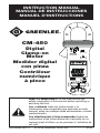
CM-450
Digital
Clamp-on
Meter
Medidor digital
con pinza
Contrôleur
numérique
à pince
52033586 REV 4 © 2019 Greenlee Tools, Inc. 9/19
CM-450
TRUE RMS

2
Description
The Greenlee CM-450 Digital Clamp-on Meter is a hand-held testing device
capable of measuring up to 600 amps of alternating current, in addition to
measuring AC or DC voltage, frequency, and resistance. It also checks diodes and
verifies continuity. The CM-450 is a true RMS-reading meter.
Safety
Safety is essential in the use and maintenance of Greenlee tools and equipment.
This instruction manual and any markings on the tool provide information for
avoiding hazards and unsafe practices related to the use of this tool. Observe all
of the safety information provided.
Purpose of This Manual
This instruction manual is intended to familiarize all personnel with the safe
operation and maintenance procedures for the Greenlee CM-450 Digital Clamp-on
Meter.
Keep this manual available to all personnel.
Replacement manuals are available upon request at no charge at
www.greenlee.com.
Do not discard this product or throw away!
For recycling information, go to www.greenlee.com.
All specifications are nominal and may change as design improvements occur.
Greenlee Tools, Inc. shall not be liable for damages resulting from misapplication or misuse
of its products.
® Registered: The color green for electrical test instruments is a registered trademark of
Greenlee Tools, Inc.
KEEP THIS MANUAL
Lifetime Limited Warranty
Greenlee Tools, Inc. warrants to the original purchaser of these goods for use
that these products will be free from defects in workmanship and material for
their useful life, excepting normal wear and abuse. This warranty is subject
to the same terms and conditions contained in Greenlee Tools, Inc.’s standard
one-year limited warranty.
For all Test Instrument repairs, contact Customer Service at 800-435-0786
and request a Return Authorization.
For items not covered under warranty (such as items dropped, abused, etc.), a
repair cost quote is available upon request.
Note: Prior to returning any test instrument, please check replaceable
batteries or make sure the battery is at full charge.

3
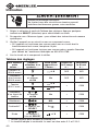
CM-450
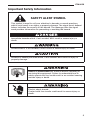
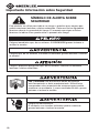
SAFETY ALERT SYMBOL
This symbol is used to call your attention to hazards or unsafe practices
which could result in an injury or property damage. The signal word, defined
below, indicates the severity of the hazard. The message after the signal
word provides information for preventing or avoiding the hazard.
Immediate hazards which, if not avoided, WILL result in severe injury or
death.
Hazards which, if not avoided, COULD result in severe injury or death.
Hazards or unsafe practices which, if not avoided, MAY result in injury or
property damage.
Read and understand this material before operating or
servicing this equipment. Failure to understand how to
safely operate this tool could result in an accident causing
serious injury or death.
Electric shock hazard:
Contact with live circuits could result in severe injury or
death.
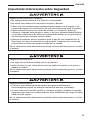
Important Safety Information

4
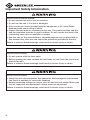
Important Safety Information
Electric shock and fire hazard:
• Do not expose this unit to rain or moisture.
• Do not use the unit if it is wet or damaged.
• Only use the test leads provided with the equipment or UL Listed Probe
Assembly with same rating or better.
• Inspect the test leads or accessory before use. They must be clean and dry,
and the insulation must be in good condition. Do not use the test lead if the
contrasting inner layer of insulation is visible.
• Use this unit for the manufacturer’s intended purpose only, as described in
this manual. Any other use can impair the protection provided by the unit.
Failure to observe these warnings could result in severe injury or death.
Electric shock hazard:
• Do not operate with the case open.
• Before opening the case, remove the test leads (or jaw) from the circuit and
shut off the unit.
Failure to observe these warnings could result in severe injury or death.
Electric shock hazard:
• Using this unit near equipment that generates electromagnetic interference
can result in unstable or inaccurate readings.
• Unless measuring voltage or current, shut off and lock out power. Make sure
that all capacitors are discharged. Voltage must not be present.
Failure to observe these warnings could result in severe injury or death.

5
CM-450
Important Safety Information
Electric shock hazard:
• Do not attempt to repair this unit. It contains no user-serviceable parts.
• Do not expose the unit to extremes in temperature or high humidity. Refer to
“Specifications.”
Failure to observe these precautions may result in injury and can damage the
unit.
Electric shock hazard:
Do not change the measurement function while the test leads are connected to
a component or circuit.
Failure to observe this precaution may result in injury and can damage the unit.
Statement of Conformity
Greenlee Tools, Inc. is certified in accordance with ISO 9001:2008 for our Quality
Management Systems.
The instrument enclosed has been checked and/or calibrated using equipment
that is traceable to the National Institute for Standards and Technology (NIST).

6
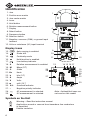
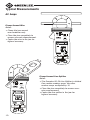
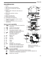
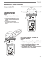
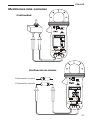
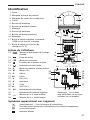
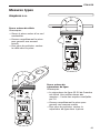
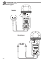
Identification
1. Jaw
2. Position error marks
3. Jaw center marks
4. Lever
5. Hold button
6. Relative measurement button
7. Display
8. Select button
9. Frequency button
10. Selector switch
11. Negative, common (COM), or ground input
terminal
12. Volts or resistance (VΩ) input terminal
Display Icons
13. Auto ranging is enabled.
14.
Diode test
15. Continuity mode
16. Hold function is enabled.
17. Low battery indicator
18. ∆ Relative measurement is enabled.
19. M Mega (10
6
)
20. Ω Ohms
21. Hz Hertz
22. k kilo (10
3
)
23. A Amps
24. V Volts
25. m milli (10
-3
)
26. O.L. Overload indicator
27. – Negative polarity indicator
28.
AC measurement is selected.
29.
DC measurement is selected.
Symbols on the Unit
Warning—Read the instruction manual
Application around or removal from hazardous live conductors
ispermitted.
Double insulation
Note: Unidentified icons are
not used on this model.
12
9
6
5
3
2
11
10
8
7
1
4
19
18
21
20
23
29
28
27
13 1514 16 17
242526
22

7
CM-450
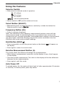
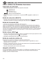
Using the Features
Selector Switch
• Slide switch to desired mode of operation:
AC voltage
DC voltage
AC current
ohms/continuity/diode
• Return switch to OFF position when not in use.
Select Button (SELECT)
• Momentarily press to select resistance, continuity, or diode test when the
Selector switch is set to .
Frequency Button (Hz)
• Press to measure frequency.
Note: The sensitivity of the frequency measurement function varies with the
measurement range. To automatically select a sensitivity level, measure the
voltage level first, and then press Hz. Pressing Hz before making a measurement
may give higher sensitivity. Reading may be zero when sensitivity is too low.
Electrical noise may cause unstable readings.
Hold Button (HOLD )
• Press momentarily to hold the present value on the display. will appear on
the display.
• Press again to return to normal mode.
Relative Measurement Button (∆)
This feature finds the difference between two measurements.
• While taking a measurement, press ∆ to set the display to zero. ∆ will appear
on the display.
• Take the second measurement. The value on the display will be the difference
between the two measurements.
• Press again to exit this mode.
Auto Power Off
To extend battery life, the meter will shut itself off after approximately 30 minutes
of inactivity. To restore power, press any button.

8
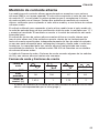
AC Measurement
AC measurements are usually displayed as RMS (root mean square) values. The
RMS value is equal to the value of a DC waveform, which would deliver the same
power if it replaced the time-varying waveform. Two AC measurement methods
are average-responding RMS calibrated and true RMS-reading.
The average-responding RMS calibrated method takes the average value of the
input signal after full wave rectification, multiplies it by 1.11, and displays the
result. This method is accurate if the input signal is a pure sine wave.
The true RMS-reading method uses internal circuitry to read the true RMS value.
This method is accurate, within the specified crest factor limitations, whether the
input signal is a pure sine wave, square wave, triangle wave, half wave, or signal
with harmonics. The ability to read true RMS provides much more measurement
versatility. The Greenlee CM-450 is a true RMS meter.
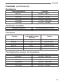
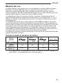
The Waveforms and Crest Factors table shows some typical AC signals and their
RMS values.
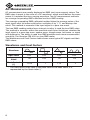
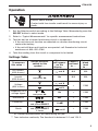
Waveforms and Crest Factors
Waveform
RMS Value 100 100 100 100
Average
Value
90 100 87 64
Crest Factor*
(x)
1.414 1 1.73 2
* The crest factor is the ratio of the peak value to the RMS value; it is
represented by the Greek letter x.

9
CM-450
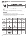
Operation
Electric shock hazard:
Contact with live circuits could result in severe injury or
death.
1. Set the Selector switch according to the Settings Table. Momentarily press the
SELECT button to select mode.
2. Refer to “Typical Measurements” for specific measurement instructions.
3. Test the unit on a known functioning circuit or component.
• If the unit does not function as expected on a known functioning circuit,
replace the battery.
• If the unit still does not function as expected, call Greenlee for technical
assistance at 800-435-0786.
4. Take the reading from the circuit or component to be tested.
Settings Table
To measure
this value …
Set the Selector
switch to this
symbol …
This icon
will appear
on the
display …
Connect
red lead
to …
Connect
black
lead
to …
AC Current*
(600 A max.)
and A N/A N/A
Frequency of a
current
(600 A max.)
and press Hz
Hz N/A N/A
Voltage
(600 V max.)
and V
+ COM
and V
Frequency of a
voltage signal
or
and press Hz
Hz + COM
Resistance MΩ + COM
Continuity**
and press SELECT
Ω
+ COM
Diode
and press SELECT
2 times
and V
+ COM
* AC current measurements are made using the jaw.
** Tone indicates continuity. The threshold is between 5 Ω and 120 Ω.

10
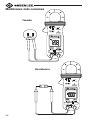
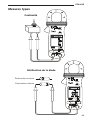
Typical Measurements
AC Amps
Clamp Around Wire
Notes:
• Clamp the jaw around
one conductor only.
• Close the jaw completely to
ensure accurate measurement.
• Center the wire in the jaw for
highest accuracy.
Clamp Around Line Splitter
Notes:
• The Greenlee 93-30 Line Splitter is divided.
One section renders amps; the other
renders amps multiplied by 10.
• Close the jaw completely to ensure accu-
rate measurement.
• Center the line splitter in the jaw for
highest accuracy.

11
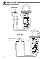
CM-450
Voltage
Typical Measurements
Resistance

12
Forward Bias
Reverse Bias
Typical Measurements
Continuity
Diode Test

13
CM-450
Accuracy
Refer to “Specifications” for operating conditions and temperature coefficient.
Accuracy is specified as follows: ± (a percentage of the reading + a fixed amount)
at 23 °C ± 5 °C (73.4 °F ± 9 °F), 0% to 75% relative humidity.
True RMS readings: Voltage is specified from 5% to 100% of the range, and AC
current is specified from 10% to 100% of the range, unless otherwise specified.
Frequency must be within the specified bandwidth for non-sinusoidal waveforms.
Crest factors are as follows:
• Crest Factor < 1.75 at full scale
• Crest Factor < 3.5 at half scale
AC Current
Measurement Range Accuracy Frequency Range
0.40 to 40.00 A ± (1.5% + 0.08 A)
50 to 60 Hz 40.0 to 400.0 A ± (1.5% + 0.8 A)
400 to 600 A ± (1.5% + 8 A)
• Adjacent conductor influence < 0.05 A/A
• Add 2% if the conductor is beyond the position error marks.
• Multiply the fixed error amount times 2 below 10% of range.
AC Voltage
Measurement
Range
Accuracy
Frequency
Range
Input
Impedance
4.000 V ± (1.5% + 0.005 V)
50 to 500 Hz
10 MΩ // 30 pF
nom.
40.00 V ± (1.5% + 0.05 V)
400.0 V ± (1.5% + 0.5 V)
600 V ± (2.0% + 5 V)
DC Voltage
Measurement Range Accuracy Input Impedance
400.0 mV ± (0.3% + 0.4 mV) 1000 MΩ*
4.000 V ± (0.5% + 0.003 V)
10 MΩ
40.00 V ± (0.5% + 0.03 V)
400.0 V ± (0.5% + 0.3 V)
600 V ± (1.0% + 4 V)
* The high impedance on this range will produce significant non-zero readings
when the test leads are disconnected from a circuit.

14
Accuracy (con’t)
Resistance
Measurement Range Accuracy
400.0 Ω ± (0.8% + 0.8 Ω)
4.000 kΩ ± (0.6% + 0.004 kΩ)
40.00 kΩ ± (0.6% + 0.04 kΩ)
400.0 kΩ ± (0.6% + 0.4 kΩ)
4.000 MΩ ± (1.0% + 0.004 MΩ)
40.00 MΩ ± (2.0% + 0.04 MΩ)
Diode Tester
Test Current Open Circuit Voltage
0.25 mA typical 1.6 VDC maximum
Frequency
Function Sensitivity (Sine RMS) Range
400.0 mV 350 mV 10 Hz to 2 kHz
4.000 V 1 V 10 Hz to 5 kHz
40.00 V 32 V 10 Hz to 100 kHz
400.0 V 100 V 10 Hz to 10 kHz
600 V 500 V 10 Hz to 5 kHz
400.0 A 60 A 40 Hz to 400 Hz
Accuracy of Frequency Ranges
Display Range Accuracy
5.000 Hz ± (0.5% + 0.004 Hz)
50.00 Hz ± (0.5% + 0.04 Hz)
500.0 Hz ± (0.5% + 0.4 Hz)
5.000 kHz ± (0.5% + 0.004 kHz)
50.00 kHz ± (0.5% + 0.04 kHz)
500.0 kHz ± (0.5% + 0.4 kHz)

15
CM-450
Specifications
Display: 3-3/4-digit LCD (4000 maximum reading)
Sampling Rate: 3 per second
Overrange Indication: “OL” appears on the display
Maximum Conductor Diameter: 26 mm (1.02")
Measurement Category: Category III, 600 V
Temperature Coefficient: 0.15 x (specified accuracy) per °C below 18 °C or above
28 °C
Operating Conditions:
At 0% ≤ 80% RH: 5 °C to 31 °C (41 °F to 86 °F)
Decreasing linearly to 50% RH at 40 °C (104 °F)
Altitude: 2000 m (6500') maximum
Indoor use only
Storage Conditions: -20 °C to 60 °C (-4 °F to 140° F), 0% to 80% relative
humidity with battery removed
Pollution Degree: 2
Battery: 3 V standard button battery (IEC-CR2032; ANSI-NEDA-54004LC)
CENELEC Directives: The instruments conform to CENELEC Low-voltage directive
2006/95/EC and Electromagnetic compatibility directive 2004/108/EC
Safety: Double insulation to IEC/UL/EN61010-1 Ed. 3.0, IEC/EN61010-2-032 Ed.
3.0, IEC/EN61010-2-033 Ed. 1.0, IEC/UL/EN61010-031 Ed. 1.1 and CAN/CSA-
C22.2 No. 61010-1-12 Ed. 3.0
All Terminals: CAT III 600 V AC/DC
Measurement Categories
These definitions were derived from the international safety standard for insula-
tion coordination as it applies to measurement, control, and laboratory equipment.
These measurement categories are explained in more detail by the International
Electrotechnical Commission; refer to either of their publications: IEC 61010-1 or
IEC 60664.
Measurement Category I: Signal level. Electronic and telecommunication equip-
ment, or parts thereof. Some examples include transient-protected electronic
circuits inside photocopiers and modems.
Measurement Category II: Local level. Appliances, portable equipment, and the
circuits they are plugged into. Some examples include light fixtures, televisions,
and long branch circuits.
Measurement Category III: Distribution level. Permanently installed machines
and the circuits they are hard-wired to. Some examples include conveyor systems
and the main circuit breaker panels of a building’s electrical system.
Measurement Category IV: Primary supply level. Overhead lines and other cable
systems. Some examples include cables, meters, transformers, and other exterior
equipment owned by the power utility.

16
Maintenance
Electric shock hazard:
• Do not attempt to repair this unit. It contains no user-serviceable parts.
• Do not expose the unit to extremes in temperature or high humidity. Refer to
“Specifications.”
Failure to observe these precautions may result in injury and can damage the
unit.
Battery Replacement
Electric shock hazard:
• Do not operate with the case open.
• Before opening the case, remove the test leads (or jaw) from the circuit and
shut off the unit.
Failure to observe these warnings could result in severe injury or death.
1. Disconnect the unit from the circuit. Turn the unit OFF.
2. Remove the screws from the back cover.
3. Remove the back cover.
4. Replace the battery (observe polarity).
5. Replace the back cover and the screws.
Cleaning
Periodically wipe the case with a damp cloth and mild detergent; do not use
abrasives or solvents.

17
CM-450
Descripción
El Medidor digital con pinza modelo CM-450 de Greenlee es un instrumento de
verificación capaz de medir hasta 600 amperios de corriente alterna, además
de medir tensión alterna o continua, frecuencia y resistencia. Esta unidad es
de bolsillo y cabe perfectamente en la palma de la mano. También sirve para
verificar diodos y continuidad. El modelo CM-450 es un multímetro de lectura de
valores eficaces reales.
Acerca de la seguridad
Es fundamental observar métodos seguros al utilizar y dar mantenimiento a las
herramientas y equipo Greenlee. Este manual de instrucciones y todas las marcas
que ostenta la herramienta le ofrecen la información necesaria para evitar riesgos
y hábitos poco seguros relacionados con su uso. Siga toda la información sobre
seguridad que se proporciona.
Propósito de este manual
Este manual de instrucciones tiene como propósito familiarizar a todo el personal
con los procedimientos de operación y mantenimiento seguros para el Medidor
digital con pinza, modelo CM-450 de Greenlee.
Manténgalo siempre al alcance de todo el personal.
Puede obtener copias adicionales de manera gratuita, previa solicitud en
www.greenlee.com.
¡No deseche ni descarte este producto!
Para información sobre reciclaje, visite www.greenlee.com.
Todas las especificaciones son nominales y pueden cambiar conforme tengan lugar mejoras
de diseño. Greenlee Tools, Inc. no se hace responsable de los daños que puedan surgir de la
mala aplicación o mal uso de sus productos.
® Registrado: El color verde para instrumentos de verificación eléctricos es una marca
registrada de Greenlee Tools, Inc.
CONSERVE ESTE MANUAL
Garantía limitada válida durante la vida útil del producto
Greenlee Tools, Inc. le garantiza al comprador original de estos bienes de uso, que los
mismos estarán libres de defectos de materiales y fabricación durante su vida útil,
excepto en el caso de que sean maltratados o hayan sufrido el deterioro normal. Esta
garantía está sujeta a los mismos términos y condiciones de la garantía estándar limitada
válida por un año, otorgada por Greenlee Tools, Inc.
Para reparaciones de todo instrumento de verificación, comuníquese con el
Departamento de Servicio al Cliente al 800-435-0786 y solicite una autorización de
devolución.
Puede obtener, previa solicitud, una cotización de precios de reparación para aquellos
artículos que no están cubiertos bajo esta garantía (los que se han dejado caer o han
sido maltratados).
Aviso: Antes de devolver un instrumento de verificación, revise si las baterías están
bajas y es necesario reemplazarlas.

18
SÍMBOLO DE ALERTA SOBRE
SEGURIDAD
Este símbolo se utiliza para indicar un riesgo o práctica poco segura que
podría ocasionar lesiones o daños materiales. Cada uno de los siguientes
términos denota la gravedad del riesgo. El mensaje que sigue a dichos
términos le indica cómo puede evitar o prevenir ese riesgo.
Peligros inmediatos que, de no evitarse, OCASIONARÁN graves lesiones o
incluso la muerte.
Peligros que, de no evitarse, PODRÍAN OCASIONAR graves lesiones o incluso
la muerte.
Peligro o prácticas peligrosas que, de no evitarse, PUEDEN OCASIONAR
lesiones o daños materiales.
Lea y entienda este documento antes de manejar
esta herramienta o darle mantenimiento. Utilizarla sin
comprender cómo manejarla de manera segura podría
ocasionar un accidente, y como resultado de éste, graves
lesiones o incluso la muerte.
Peligro de electrocución:
El contacto con circuitos activados podría ocasionar
graves lesiones o incluso la muerte.
Importante Información sobre Seguridad

19
CM-450
Importante Información sobre Seguridad
Peligro de electrocución e incendio:
• No exponga esta unidad ni a la lluvia ni a la humedad.
• No utilice esta unidad si se encuentra mojada o dañada.
• Utilice solo los conductores de prueba proporcionados con el equipo o un
conjunto de sonda con certificación UL con una calificación igual o superior.
• Revise minuciosamente los cables de prueba o el accesorio, antes de
utilizarlos. Deberán estar limpios y secos, y su forro aislante deberá hallarse
en buenas condiciones. No utilice el conductor de prueba si la capa interna
de aislamiento en contraste resulta visible.
• Utilícela únicamente para el propósito para el que ha sido diseñada por el
fabricante, tal como se describe en este manual. Cualquier otro uso puede
menoscabar la protección proporcionada por la unidad.
De no observarse estas advertencias podrían sufrirse lesiones graves o incluso
la muerte.
Peligro de electrocución:
• No haga funcionar esta unidad con la caja abierta.
• Antes de abrir la caja, retire del circuito los cables de prueba (o la pinza), y
apague la unidad.
De no observarse estas advertencias podrían sufrirse lesiones graves o incluso
la muerte.
Peligro de electrocución:
• Al utilizar esta unidad cerca de equipo que genere interferencia
electromagnética quizá se obtenga una lectura inexacta e inestable.
• A menos que vaya a medir tensión o corriente, apague y bloquee la energía.
Asegúrese que todos los condensadores estén totalmente sin carga. No debe
haber tensión alguna.
De no observarse estas advertencias podrían sufrirse lesiones graves o incluso
la muerte.

20
Importante Información sobre Seguridad
Peligro de electrocución:
• No intente reparar esta unidad, ya que contiene partes que deben recibir
mantenimiento por parte de un profesional.
• No exponga la unidad a ambientes de temperatura extrema o altos niveles
de humedad. Consulte la sección “Especificaciones”.
De no observarse estas precauciones podrían sufrirse lesiones o daños a la
unidad.
Peligro de electrocución:
No cambie la función de medición mientras los cables de prueba estén
conectados a un componente o circuito.
De no observarse esta advertencia podrían sufrirse lesiones o daños a la
unidad.
Certificado de Conformidad
Greenlee Tools, Inc. cuenta con certificación conforme a ISO 9001:2008 para
nuestros Sistemas de Gerencia de Calidad.
El instrumento provisto ha sido inspeccionado y/o calibrado mediante el uso de
equipo reconocido por el Instituto Nacional de Normas y Tecnologías (National
Institute for Standards and Technology [NIST]).
La page charge ...
La page charge ...
La page charge ...
La page charge ...
La page charge ...
La page charge ...
La page charge ...
La page charge ...
La page charge ...
La page charge ...
La page charge ...
La page charge ...
La page charge ...
La page charge ...
La page charge ...
La page charge ...
La page charge ...
La page charge ...
La page charge ...
La page charge ...
La page charge ...
La page charge ...
La page charge ...
La page charge ...
La page charge ...
La page charge ...
La page charge ...
La page charge ...
-
 1
1
-
 2
2
-
 3
3
-
 4
4
-
 5
5
-
 6
6
-
 7
7
-
 8
8
-
 9
9
-
 10
10
-
 11
11
-
 12
12
-
 13
13
-
 14
14
-
 15
15
-
 16
16
-
 17
17
-
 18
18
-
 19
19
-
 20
20
-
 21
21
-
 22
22
-
 23
23
-
 24
24
-
 25
25
-
 26
26
-
 27
27
-
 28
28
-
 29
29
-
 30
30
-
 31
31
-
 32
32
-
 33
33
-
 34
34
-
 35
35
-
 36
36
-
 37
37
-
 38
38
-
 39
39
-
 40
40
-
 41
41
-
 42
42
-
 43
43
-
 44
44
-
 45
45
-
 46
46
-
 47
47
-
 48
48


Greenlee CM-450 Digital Clamp-on Meter Manual Manuel utilisateur
- Taper
- Manuel utilisateur
- Ce manuel convient également à
dans d''autres langues
Documents connexes
-
Greenlee CM-450 Digital Clamp-on Meter Manuel utilisateur
-
Greenlee DM-25 Digital Multimeter Manuel utilisateur
-
-
Greenlee DM45 Le manuel du propriétaire
-
-
-
-
-
-