
OWNER’S MANUAL
E 2018 Miller Electric Mfg. LLC
OM-2811 221385G
2018−05
For PRHC-14 Remote Control 195511
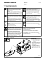
1. Safety Symbol Definitions
DANGER! − Indicates a hazardous situation which, if not
avoided, will result in death or serious injury. The pos-
sible hazards are shown in the adjoining symbols or
explained in the text.
DANGER ! - Indique une situation dangereuse qui, si
elle n’est pas évitée, entraînera la mort ou des blessures
graves. Les éventuels risques sont représentés par les
symboles joints ou expliqués dans le texte.
Fsafe1 2013-10
Beware of electric shock from wiring. Stop engine and
disconnect negative (−) cable from battery before install-
ing this kit. Reinstall all panels and covers.
Attention aux chocs électriques des câbles. Arrêter le
moteur et débrancher le câble négatif de la batterie
avant d’installer cet ensemble. Réinstaller tous les
panneaux et couvercles.
Engsafe1 2013-10
Indicates a hazardous situation which, if not avoided,
could result in death or serious injury. The possible ha-
zards are shown in the adjoining symbols or explained in
the text.
Indique une situation dangereuse qui, si elle n’est pas
évitée, entraînera la mort ou des blessures graves. Les
éventuels risques sont représentés par les symboles
joints ou expliqués dans le texte.
Fsafe2 2013-10
Welding sparks can cause fire or explosion. Move flam-
mables away. Do not weld on closed tanks or barrels, or
on containers that have held combustibles − they can
explode. Clean tanks or barrels properly.
Les étincelles de soudure peuvent provoquer un in-
cendie ou une explosion. Ne pas souder de cuves ou de
tonneaux, au risque qu’ils explosent. Nettoyer soigneu-
sement les cuves ou tonneaux.
Fsafe9 2018-01
NOTICE
AVIS
Indicates statements not related to personal injury.
Signale des consignes non associées aux dommages
corporels.
Indicates special instructions.
Fournit des instructions spéciales.
Fsafe3 2013-10
Wear safety glasses with side shields.
Porter des lunettes de sécurité avec écrans latéraux.
Fsafe8 2013-10
Overheating can damage motors. Turn off or unplug
equipment before starting or stopping engine. Do not let
low voltage and frequency caused by low engine speed
damage electric motors. Do not connect 50 or 60 Hertz
motors to the 100 Hertz receptacle where applicable.
Le surchauffement peut endommager le moteur
électrique. Arrêter ou débrancher l’appareil avant
de démarrer ou d’arrêter le moteur. N’endommagez pas
les moteurs électriques avec un régime moteur lent
produisant une tension et une fréquence trop basses.
Ne pas connecter les moteurs de 50 ou 60 Hertz
à la prise de 100 Hertz si elle existe.
Engsafe11 2013-10
CALIFORNIA PROPOSITION 65 WARNINGS
WARNING: Cancer and Reproductive Harm −
www.P65Warnings.ca.gov
PROPOSITION CALIFORIENNE 65 AVERTISSEMENTS
AVERTISSEMENT : cancer et troubles de la reproduction −
www.P65Warnings.ca.gov.
Fsafe26 2018-01
2. Typical Connection
! Stop engine.
1 PRHC-14 Remote Control
2 120 V AC Auxiliary Power
Receptacle
Insert PRHC-14 auxiliary power
plug into matching non-GFCI (if
available) 120 V AC receptacle on
welder/generator.
3 Remote 14 Receptacle
Insert PRHC-14 remote 14-pin
plug into matching 14-pin recepta-
cle on welder/generator. Tighten
collar.
1
803 940−C
3
2

OM-2811 Page 2
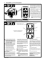
3. Using PRHC-14 120 V AC Receptacle
1 120 V 20 A AC GFCI Receptacle
Receptacle supplies 60 Hz single-phase
power at weld/power speed. Maximum
output from receptacle equals maximum
output from corresponding receptacle
on welder/ generator.
Overload protection is provided by the
corresponding AC receptacle circuit
breaker on the welder/generator.
If a ground fault is detected, the
PRHC-14 GFCI Reset button pops out
and the receptacle does not work.
Check for faulty tools plugged in to re-
ceptacle. Press RESET button to reset
GFCI receptacle and resume operation.
. At least once a month, run engine at
weld/power speed and press test
button to verify GFCI is working
properly.
1
803 939-B
4. GFCI Receptacle Information, Resetting, And Testing
! Use GFCI protection when operat-
ing auxiliary equipment. If unit does
not have GFCI receptacles, use
GFCI-protected extension cord. Do
not use GFCI receptacle to power
life support equipment.
! Unplug power cord before attempt-
ing to service accessories or tools.
1 120 V 20 A AC GFCI Receptacle
2 GFCI Receptacle Test Button
3 GFCI Receptacle Reset Button
4 Red GFCI Indicator Light (LED)
5 Green GFCI Indicator Light (LED)
. Red and Green indicator lights may be
combined in a single LED.
GFCI Receptacles
GFCI receptacles protect the user from
electric shock if a ground fault occurs in
equipment connected to the receptacle. A
ground fault occurs when electrical current
takes the shortest path to ground (which
could be through a person) rather than fol-
low its intended safe path.
If a ground fault is detected, the GFCI Re-
set button pops out, and the circuit opens
to disconnect power to the faulty equip-
ment. A GFCI receptacle does not protect
against circuit overloads, short circuits, or
shocks not related to ground faults. Reset
and test GFCI receptacle according to the
following procedures.
A solid green LED indicates power to the
GFCI. A solid red LED indicates that the
GFCI has been tripped.
Resetting/Testing GFCI Receptacle
! Test GFCI monthly.
! If Red LED blinks, stop using GFCI
receptacle and have it replaced by
a Factory Authorized Service
Agent.
! Extension cords with bad insula-
tion or of extended length can allow
enough leakage current to trip the
GFCI circuit. Reset and test as
follows.
Resetting GFCI Receptacles
If a GFCI fault occurs, stop engine and dis-
connect equipment from GFCI receptacle.
Check for damaged or wet tools, cords,
plugs, etc. connected to the receptacle.
Start engine, place ignition switch in RUN
position, and press GFCI Reset button.
Reconnect equipment to GFCI receptacle.
If GFCI Reset button pops out again,
check the equipment and repair or replace
if faulty.
Testing GFCI Receptacles
Start engine and press the GFCI Test but-
ton. The GFCI Reset button should pop
out.
Press the GFCI Reset button.
Have GFCI replaced by a Factory Au-
thorized Service Agent if any of the fol-
lowing occur:
GFCI does not trip when tested
Red LED blinks
GFCI does not reset.
1
2
3
4
RotGFCI1 2018-01
5
. Orientation of receptacle may be
different in other applications.
. Alternate location for red
and green indicator LEDs.

OM-2811 Page 3
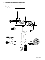
5. Combination Remote Amperage/Voltage Control
.
See welder/generator Owner’s Manual for information on using remote controls with your unit. Visit www.MillerWelds.com or call the Literature
Dept. at 920-735-4356 if you need an Owner’s Manual for your model welder/generator.
6. Wiring Diagram
221 384−D

OM-2811 Page 4
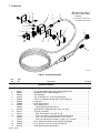
7. Parts List
.
Hardware is common and
not available unless listed.
803 938−D
7
3
6
2
8
910
11
12
131415
! Read warning label on
remote control before
servicing.
4
5
1
Figure 1. Complete Assembly
Description
Part
No.
Item
No.
Complete Assembly
Quantity
1 221391 Cover, Receptacle Single Gang GFCI Weather Proof 1... ... .............. ................
2 282067 Receptacle, GFCI 15/20A w/Mtg Tabs 1... ... .............. ..............................
3 221393 Terminal Block 1... ... .............. ...................................................
4 221504 Pot, Cp Std Slot 1t 2. W 1k Linear W/Leads 1... ... .............. .........................
5 600760 Term, Frict 250x032 Uninsul Male .130 Stud Mtg 1pr 1... ... .............. .................
6 222002 Lead Assy 1... ... .............. ......................................................
7 234988 Cage, Hand Control 1... ... .............. ..............................................
8 221380 Box, Outlet/Control 1... ... .............. ...............................................
196003 Label, Warning Remote Control 1......... ............... ..................................
9 221383 Strain Relief, 3/4 Npt Galv Steel .520−.730 Cord 1... ... .............. .....................
10 221473 Cord Set, (includes) 1... ... .............. ..............................................
11 221474 Plug, Str Grd 2p3w 15A 125V *5−15p 1... ... ............... ............................
12 134734 Conn, Circ Ms/Cpc 14pin Size 20 Plug Cable Pushin 1... ... ............... ...............
079739 Conn, Circ Cpc Clamp Str Rlf Size 17−20 .703od 1......... ............... ..................
134731 Conn, Circ Ms/Amp Pin Pushin 14−18ga .110−.150 Insu 3......... ............... ............
13 097926 Knob, Pointer 2.375 Dia X .250 Id W/Set Screwsplstc 1... ... .............. ................
14 072590 Lock, Shaft Pot .375−32 X .250 Dia Shaft Tall 1... ... .............. .......................
15 221378 Plate, Ident Remote Hand Control 1... ... .............. .................................
-
 1
1
-
 2
2
-
 3
3
-
 4
4


Miller PRHC-14 REMOTE CONTROL 195511 Le manuel du propriétaire
- Taper
- Le manuel du propriétaire
- Ce manuel convient également à
dans d''autres langues
Documents connexes
-
Miller ADAPTER CORD Le manuel du propriétaire
-
-
-
-
-
-
-
-
-
Miller BIG BLUE 700 DUO PRO Le manuel du propriétaire